2006 INFINITI M35 check oil
[x] Cancel search: check oilPage 1297 of 5621

BR-22
VACUUM LINES
Revision: 2006 January2006 M35/M45
Removal and InstallationNFS000P9
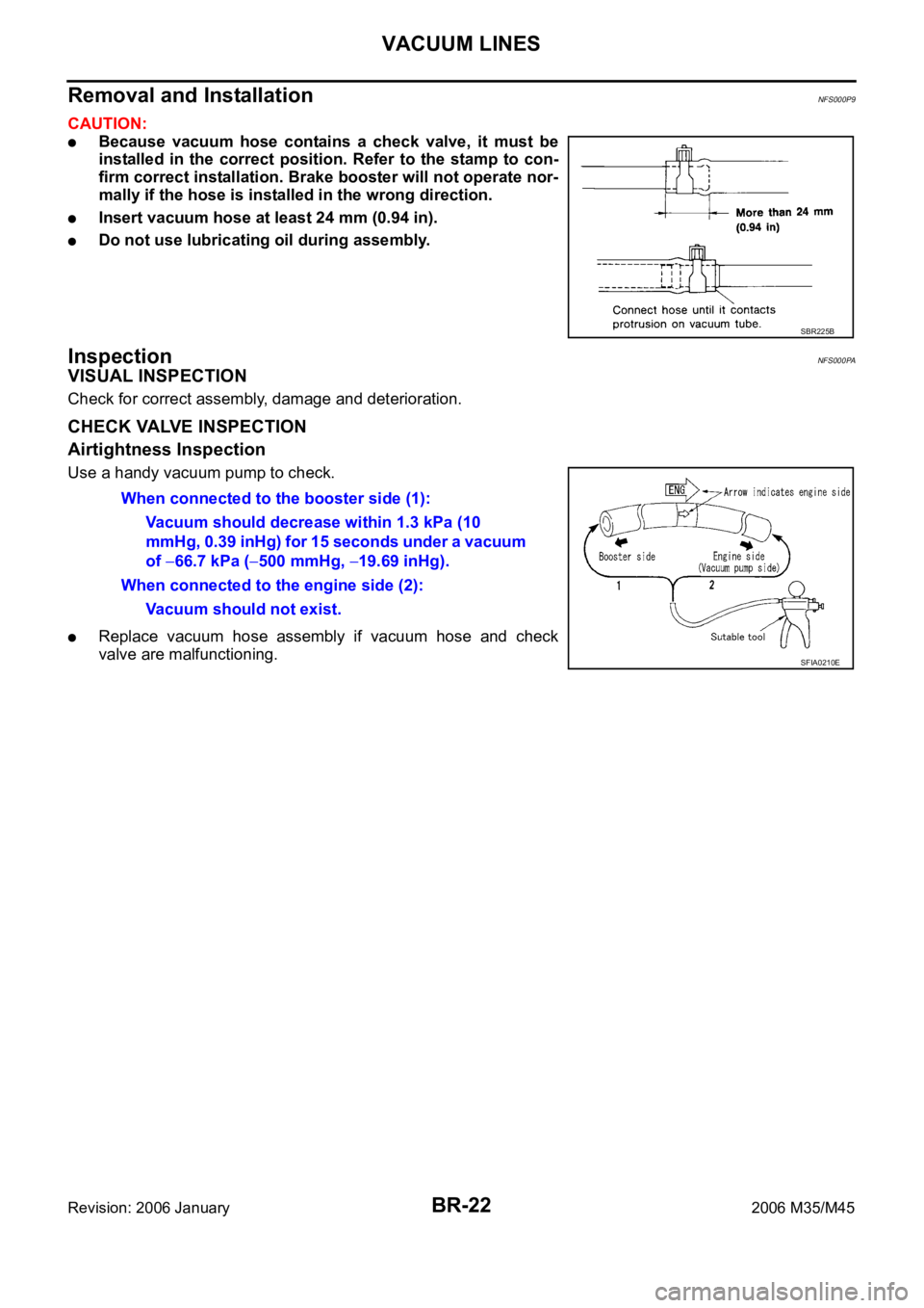
CAUTION:
Because vacuum hose contains a check valve, it must be
installed in the correct position. Refer to the stamp to con-
firm correct installation. Brake booster will not operate nor-
mally if the hose is installed in the wrong direction.
Insert vacuum hose at least 24 mm (0.94 in).
Do not use lubricating oil during assembly.
InspectionNFS000PA
VISUAL INSPECTION
Check for correct assembly, damage and deterioration.
CHECK VALVE INSPECTION
Airtightness Inspection
Use a handy vacuum pump to check.
Replace vacuum hose assembly if vacuum hose and check
valve are malfunctioning.
SBR225B
When connected to the booster side (1):
Vacuum should decrease within 1.3 kPa (10
mmHg, 0.39 inHg) for 15 seconds under a vacuum
of
66.7 kPa (500 mmHg, 19.69 inHg).
When connected to the engine side (2):
Vacuum should not exist.
SFIA0210E
Page 1300 of 5621

FRONT DISC BRAKE
BR-25
C
D
E
G
H
I
J
K
L
MA
B
BR
Revision: 2006 January2006 M35/M45
Removal and Installation of Brake Caliper AssemblyNFS000PE
REMOVAL
1. Remove tires from vehicle with power tool.
2. Fasten disc rotor using wheel nut.
3. Drain brake fluid. Refer to BR-10, "
Drain and Refill" .
4. Remove union bolt, and then disconnect brake hose from caliper assembly.
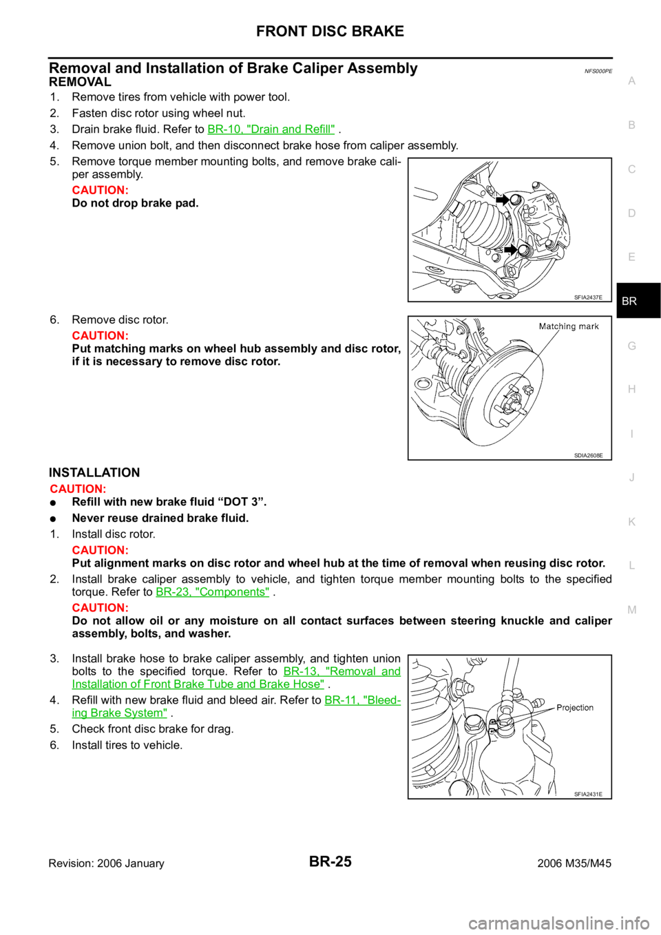
5. Remove torque member mounting bolts, and remove brake cali-
per assembly.
CAUTION:
Do not drop brake pad.
6. Remove disc rotor.
CAUTION:
Put matching marks on wheel hub assembly and disc rotor,
if it is necessary to remove disc rotor.
INSTALLATION
CAUTION:
Refill with new brake fluid “DOT 3”.
Never reuse drained brake fluid.
1. Install disc rotor.
CAUTION:
Put alignment marks on disc rotor and wheel hub at the time of removal when reusing disc rotor.
2. Install brake caliper assembly to vehicle, and tighten torque member mounting bolts to the specified
torque. Refer to BR-23, "
Components" .
CAUTION:
Do not allow oil or any moisture on all contact surfaces between steering knuckle and caliper
assembly, bolts, and washer.
3. Install brake hose to brake caliper assembly, and tighten union
bolts to the specified torque. Refer to BR-13, "
Removal and
Installation of Front Brake Tube and Brake Hose" .
4. Refill with new brake fluid and bleed air. Refer to BR-11, "
Bleed-
ing Brake System" .
5. Check front disc brake for drag.
6. Install tires to vehicle.
SFIA2437E
SDIA2608E
SFIA2431E
Page 1301 of 5621

BR-26
FRONT DISC BRAKE
Revision: 2006 January2006 M35/M45
Disassembly and Assembly of Brake Caliper AssemblyNFS000PF
NOTE:
Do not remove torque member, pads, shims, shim covers, and pad retainers when disassembling and assem-
bling cylinder body assembly.
DISASSEMBLY
1. Remove sliding pin bolt, and then remove cylinder body from torque member.
CAUTION:
Do not drop pads, shims, shim cover and pad retainers from torque member.
2. Remove sliding pins and sliding pin boots from torque member.
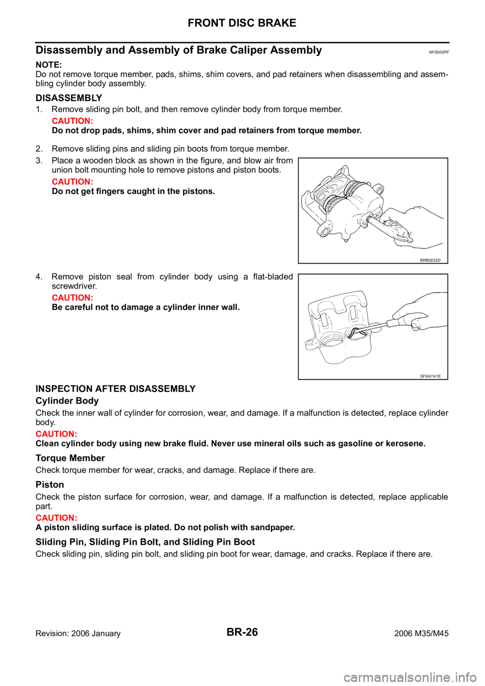
3. Place a wooden block as shown in the figure, and blow air from
union bolt mounting hole to remove pistons and piston boots.
CAUTION:
Do not get fingers caught in the pistons.
4. Remove piston seal from cylinder body using a flat-bladed
screwdriver.
CAUTION:
Be careful not to damage a cylinder inner wall.
INSPECTION AFTER DISASSEMBLY
Cylinder Body
Check the inner wall of cylinder for corrosion, wear, and damage. If a malfunction is detected, replace cylinder
body.
CAUTION:
Clean cylinder body using new brake fluid. Never use mineral oils such as gasoline or kerosene.
Torque Member
Check torque member for wear, cracks, and damage. Replace if there are.
Piston
Check the piston surface for corrosion, wear, and damage. If a malfunction is detected, replace applicable
part.
CAUTION:
A piston sliding surface is plated. Do not polish with sandpaper.
Sliding Pin, Sliding Pin Bolt, and Sliding Pin Boot
Check sliding pin, sliding pin bolt, and sliding pin boot for wear, damage, and cracks. Replace if there are.
BRB0032D
SFIA0141E
Page 1306 of 5621

REAR DISC BRAKE
BR-31
C
D
E
G
H
I
J
K
L
MA
B
BR
Revision: 2006 January2006 M35/M45
Removal and Installation of Brake Caliper AssemblyNFS000PJ
REMOVAL
1. Remove tires from vehicle with power tool.
2. Fasten disc rotor using wheel nut.
3. Drain brake fluid. Refer to BR-10, "
Drain and Refill" .
4. Remove union bolt and then disconnect brake hose from caliper
assembly.
5. Remove torque member mounting, bolts, and remove brake cal-
iper assembly.
CAUTION:
Do not drop brake pad.
6. Remove disc rotor.
CAUTION:
Put matching marks on wheel hub assembly and disc rotor,
if it necessary to remove disc rotor.
INSTALLATION
CAUTION:
Refill with new brake fluid “DOT 3”.
Never reuse drained brake fluid.
1. Install disc rotor.
CAUTION:
Alignment marks of disc rotor and wheel hub put at the time of removal when reusing disc rotor.
2. Install brake caliper assembly vehicle, and tighten torque member mounting bolts to the specified torque.
CAUTION:
Before installing caliper assembly, wipe off oil and moisture on all mounting surfaces of rear axle
and caliper assembly and threads, bolts and washers.
3. Install L-shaped pin of brake hose and then tighten union bolt to
the specified torque. Refer to BR-13, "
Removal and Installation
of Rear Brake Tube and Brake Hose" .
4. Refill with new brake fluid and bleed air. Refer to BR-11, "
Bleed-
ing Brake System" .
5. Check rear disc brake for drag.
6. Install tires to vehicle.
SFIA2972E
SDIA2638E
SFIA2049E
Page 1307 of 5621

BR-32
REAR DISC BRAKE
Revision: 2006 January2006 M35/M45
Disassembly and Assembly of Brake Caliper AssemblyNFS000PK
NOTE:
Do not remove torque member, pads, shims, shim covers, and pad retainers when disassembling and assem-
bling cylinder body assembly.
DISASSEMBLY
1. Remove sliding pin bolt, and then remove cylinder body from torque member.
CAUTION:
Do not drop pads, shims, shim cover and pad retainers from torque member.
2. Remove sliding pin boot from torque member.
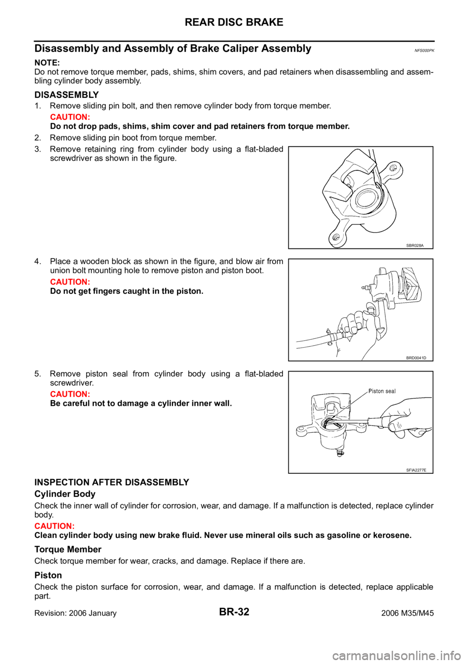
3. Remove retaining ring from cylinder body using a flat-bladed
screwdriver as shown in the figure.
4. Place a wooden block as shown in the figure, and blow air from
union bolt mounting hole to remove piston and piston boot.
CAUTION:
Do not get fingers caught in the piston.
5. Remove piston seal from cylinder body using a flat-bladed
screwdriver.
CAUTION:
Be careful not to damage a cylinder inner wall.
INSPECTION AFTER DISASSEMBLY
Cylinder Body
Check the inner wall of cylinder for corrosion, wear, and damage. If a malfunction is detected, replace cylinder
body.
CAUTION:
Clean cylinder body using new brake fluid. Never use mineral oils such as gasoline or kerosene.
Torque Member
Check torque member for wear, cracks, and damage. Replace if there are.
Piston
Check the piston surface for corrosion, wear, and damage. If a malfunction is detected, replace applicable
part.
SBR028A
BRD0041D
SFIA2277E
Page 1314 of 5621
![INFINITI M35 2006 Factory Service Manual PRECAUTIONS
BRC-3
[VDC/TCS/ABS]
C
D
E
G
H
I
J
K
L
MA
B
BRC
Revision: 2006 January2006 M35/M45
[VDC/TCS/ABS]PRECAUTIONSPFP:00001
Precautions for Supplemental Restraint System (SRS) “AIR BAG” and � INFINITI M35 2006 Factory Service Manual PRECAUTIONS
BRC-3
[VDC/TCS/ABS]
C
D
E
G
H
I
J
K
L
MA
B
BRC
Revision: 2006 January2006 M35/M45
[VDC/TCS/ABS]PRECAUTIONSPFP:00001
Precautions for Supplemental Restraint System (SRS) “AIR BAG” and �](/manual-img/42/57023/w960_57023-1313.png)
PRECAUTIONS
BRC-3
[VDC/TCS/ABS]
C
D
E
G
H
I
J
K
L
MA
B
BRC
Revision: 2006 January2006 M35/M45
[VDC/TCS/ABS]PRECAUTIONSPFP:00001
Precautions for Supplemental Restraint System (SRS) “AIR BAG” and “SEAT
BELT PRE-TENSIONER”
NFS000PY
The Supplemental Restraint System such as “AIR BAG” and “SEAT BELT PRE-TENSIONER”, used along
with a front seat belt, helps to reduce the risk or severity of injury to the driver and front passenger for certain
types of collision. This system includes seat belt switch inputs and dual stage front air bag modules. The SRS
system uses the seat belt switches to determine the front air bag deployment, and may only deploy one front
air bag, depending on the severity of a collision and whether the front occupants are belted or unbelted.
Information necessary to service the system safely is included in the SRS and SB section of this Service Man-
ual.
WAR NING :
To avoid rendering the SRS inoperative, which could increase the risk of personal injury or death
in the event of a collision which would result in air bag inflation, all maintenance must be per-
formed by an authorized NISSAN/INFINITI dealer.
Improper maintenance, including incorrect removal and installation of the SRS, can lead to per-
sonal injury caused by unintentional activation of the system. For removal of Spiral Cable and Air
Bag Module, see the SRS section.
Do not use electrical test equipment on any circuit related to the SRS unless instructed to in this
Service Manual. SRS wiring harnesses can be identified by yellow and/or orange harnesses or
harness connectors.
Precautions for Procedures without Cowl Top CoverNFS000PZ
When performing the procedure after removing cowl top cover, cover
the lower end of windshield with urethane, etc.
Precautions for Brake SystemNFS000Q0
Recommended fluid is brake fluid “DOT 3”.
Never reuse drained brake fluid.
Be careful not to splash brake fluid on painted surface of body. If brake fluid is splashed on painted sur-
faces of body immediately wipe off then with cloth and then wash it away with water.
Never use mineral oils such as gasoline or kerosene. They will ruin rubber parts of the hydraulic system.
Use a flare nut wrench when removing flare nuts, and use a flare
nut torque wrench when tighten brake tube flare nuts.
When installing brake tubes, be sure to check torque.
Brake system is an important safety part. If a brake fluid leak is
detected, always disassemble the affected part. If a malfunction
is detected, replace part with a new one.
Before working, turn ignition switch OFF and disconnect con-
nectors of ABS actuator and electric unit (control unit) or the bat-
tery cable from the negative terminal.
WAR NING :
Clean brake pads and shoes with a waste cloth, then wipe with
a dust collector.
PIIB3706J
SBR686C
Page 1315 of 5621
![INFINITI M35 2006 Factory Service Manual BRC-4
[VDC/TCS/ABS]
PRECAUTIONS
Revision: 2006 January2006 M35/M45
Precautions for Brake ControlNFS000Q1
Just after starting vehicle after ignition switch ON, brake pedal may vibrate or motor operatin INFINITI M35 2006 Factory Service Manual BRC-4
[VDC/TCS/ABS]
PRECAUTIONS
Revision: 2006 January2006 M35/M45
Precautions for Brake ControlNFS000Q1
Just after starting vehicle after ignition switch ON, brake pedal may vibrate or motor operatin](/manual-img/42/57023/w960_57023-1314.png)
BRC-4
[VDC/TCS/ABS]
PRECAUTIONS
Revision: 2006 January2006 M35/M45
Precautions for Brake ControlNFS000Q1
Just after starting vehicle after ignition switch ON, brake pedal may vibrate or motor operating noise may
be heard from engine compartment. This is normal condition.
When an error is indicated by ABS or another warning lamp, collect all necessary information from cus-
tomer (what symptoms are present under what conditions) and check for simple causes before starting
diagnostic servicing. Besides electrical system inspection, check brake booster operation, brake fluid
level, and oil leaks.
If tire size and type are used in an improper combination, or brake pads are not Genuine NISSAN parts,
stopping distance or steering stability may deteriorate.
ABS might be out of order or malfunctions by putting a radio (wiring inclusive), an antenna and a lead-in
wire near the control unit.
If aftermarket parts (car stereo, CD player, etc.) have been installed, check for incidents such as harness
pinches, open circuits, and improper wiring.
VDC system may not operate normally or a VDC OFF indicator lamp or SLIP indicator lamp may light.
–When replacing the following parts with parts other than genuine parts or making modifications: Suspen-
sion-related parts (shock absorber, spring, bushing, etc.), tires, wheels (other than specified sizes), brake-
related parts (pad, rotor, caliper, etc.), engine-related parts (muffler, ECM, etc.) and body reinforcement-
related parts (roll bar, tower bar, etc.).
–When driving with worn or deteriorated suspension, tires and brake-related parts.
Page 1391 of 5621
![INFINITI M35 2006 Factory Service Manual CO-16
[VQ35DE]
RADIATOR
Revision: 2006 January2006 M35/M45
Minimize the lift of A/C condenser to prevent load from being applied to A/C piping.
e. After removing the radiator, place the A/C con INFINITI M35 2006 Factory Service Manual CO-16
[VQ35DE]
RADIATOR
Revision: 2006 January2006 M35/M45
Minimize the lift of A/C condenser to prevent load from being applied to A/C piping.
e. After removing the radiator, place the A/C con](/manual-img/42/57023/w960_57023-1390.png)
CO-16
[VQ35DE]
RADIATOR
Revision: 2006 January2006 M35/M45
Minimize the lift of A/C condenser to prevent load from being applied to A/C piping.
e. After removing the radiator, place the A/C condenser on the radiator core support to prevent load from
being applied to piping. And then, temporarily secure them using a rope to prevent them from being
dropped.
INSTALLATION
Installation is the reverse order of removal.
INSPECTION AFTER INSTALLATION
Check for leaks of engine coolant using the radiator cap tester adapter [SST: EG17650301 (J33984-A)]
and the radiator cap tester (commercial service tool). Refer to CO-11, "
LEAK CHECK" .
Start and warm up the engine. Visually make sure that there is no leaks of engine coolant and A/T fluid.
Checking Radiator CapNBS004QU
Check valve seat of radiator cap.
–Check if valve seat is swollen to the extent that the edge of the
plunger cannot be seen when watching it vertically from the top.
–Check if valve seat has no soil and damage.
Pull negative-pressure valve to open it, and make sure that it
close completely when released.
–Make sure that there is no dirt or damage on the valve seat of
radiator cap negative-pressure valve.
–Make sure that there are no unusualness in the opening and
closing conditions of negative-pressure valve.
Check radiator cap relief pressure.
–When connecting radiator cap to the radiator cap tester (com-
mercial service tool) and the radiator cap tester adapter (SST),
apply engine coolant to the cap seal surface.
Replace radiator cap if there is an unusualness related to the above three.
CAUTION:
When installing radiator cap, thoroughly wipe out the radiator filler neck to remove any waxy residue
or foreign material.
Checking RadiatorNBS004QV
Check radiator for mud or clogging. If necessary, clean radiator as follows.
Be careful not to bend or damage radiator fins.
PBIC2816E
SMA967B
Standard:
78 - 98 kPa (0.8 - 1.0 kg/cm
2 , 11 - 14 psi)
Limit:
59 kPa (0.6 kg/cm
2 , 9 psi)
SLC755A