2006 INFINITI M35 display
[x] Cancel search: displayPage 3701 of 5621
![INFINITI M35 2006 Factory Service Manual LAN-32
[CAN]
TROUBLE DIAGNOSES WORK FLOW
Revision: 2006 January2006 M35/M45
DESCRIPTION OF “CAN DIAG SUPPORT MNTR” SCREEN
FOR ICC SENSOR INTEGRATED UNIT
Display Results (Present)
OK: Normal
UNKWN INFINITI M35 2006 Factory Service Manual LAN-32
[CAN]
TROUBLE DIAGNOSES WORK FLOW
Revision: 2006 January2006 M35/M45
DESCRIPTION OF “CAN DIAG SUPPORT MNTR” SCREEN
FOR ICC SENSOR INTEGRATED UNIT
Display Results (Present)
OK: Normal
UNKWN](/manual-img/42/57023/w960_57023-3700.png)
LAN-32
[CAN]
TROUBLE DIAGNOSES WORK FLOW
Revision: 2006 January2006 M35/M45
DESCRIPTION OF “CAN DIAG SUPPORT MNTR” SCREEN
FOR ICC SENSOR INTEGRATED UNIT
Display Results (Present)
OK: Normal
UNKWN: The diagnosed unit does not transmit or receive the applicable data normally.
–: There is no received unit or the unit is not in the condition that reception diagnosis is performed.
Display Results (Past)
OK: Normal
0: There is malfunction now.
1 ~ 39: Displays when it is normal at present and finds malfunction in the past. It increases like 012...3839 after returning to the
normal condition whenever IGN OFF
ON. If it is over 39, it is fixed to 39 until the self-diagnostic results are erased. It returns to 0
when malfunction is detected again in the process.
–: Undiagnosed
PKIB9801E
“SELECT SYSTEM”
screen“CAN DIAG SUP-
PORT MNTR”
screenDescription Present Past
ICCTRANSMIT DIAG Make sure of normal transmission. OK/UNKWN/–
OK/0/1~39/– ECM Make sure of normal reception from ECM. OK/UNKWN/–
VDC/TCS/ABSMake sure of normal reception from ABS actuator and
electric unit (control unit).OK/UNKWN/–
METER/M&AMake sure of normal reception from unified meter and A/C
amp.OK/UNKWN/–
BCM/SEC Make sure of normal reception from BCM. OK/UNKWN/–
TCM Make sure of normal reception from TCM. OK/UNKWN/–
STRG STRG is not diagnosed. –
Page 3702 of 5621
![INFINITI M35 2006 Factory Service Manual TROUBLE DIAGNOSES WORK FLOW
LAN-33
[CAN]
C
D
E
F
G
H
I
J
L
MA
B
LAN
Revision: 2006 January2006 M35/M45
DESCRIPTION OF “CAN DIAG SUPPORT MNTR” SCREEN
FOR IPDM E/R
Display Results (Present)
OK: Nor INFINITI M35 2006 Factory Service Manual TROUBLE DIAGNOSES WORK FLOW
LAN-33
[CAN]
C
D
E
F
G
H
I
J
L
MA
B
LAN
Revision: 2006 January2006 M35/M45
DESCRIPTION OF “CAN DIAG SUPPORT MNTR” SCREEN
FOR IPDM E/R
Display Results (Present)
OK: Nor](/manual-img/42/57023/w960_57023-3701.png)
TROUBLE DIAGNOSES WORK FLOW
LAN-33
[CAN]
C
D
E
F
G
H
I
J
L
MA
B
LAN
Revision: 2006 January2006 M35/M45
DESCRIPTION OF “CAN DIAG SUPPORT MNTR” SCREEN
FOR IPDM E/R
Display Results (Present)
OK: Normal
UNKWN: The diagnosed unit does not transmit or receive the applicable data normally.
–: There is no received unit or the unit is not in the condition that reception diagnosis is performed.
Display Results (Past)
OK: Normal
0: There is malfunction now.
1 ~ 39: Displays when it is normal at present and finds malfunction in the past. It increases like 012...3839 after returning to the
normal condition whenever IGN OFF
ON. If it is over 39, it is fixed to 39 until the self-diagnostic results are erased. It returns to 0
when malfunction is detected again in the process.
–: Undiagnosed
SKIB0595E
“SELECT SYSTEM”
screen“CAN DIAG SUPPORT
MNTR” screenDescription Present Past
IPDM E/RTRANSMIT DIAG Make sure of normal transmission. OK/UNKWN/–
OK/0/1~39/– ECM Make sure of normal reception from ECM. OK/UNKWN/–
BCM/SEC Make sure of normal reception from BCM. OK/UNKWN/–
Page 3710 of 5621
![INFINITI M35 2006 Factory Service Manual CAN COMMUNICATION
LAN-41
[CAN]
C
D
E
F
G
H
I
J
L
MA
B
LAN
Revision: 2006 January2006 M35/M45
Blower fan motor switch signal R T
Buzzer output signalTR
TR
RT
Day time running light request signal T R
D INFINITI M35 2006 Factory Service Manual CAN COMMUNICATION
LAN-41
[CAN]
C
D
E
F
G
H
I
J
L
MA
B
LAN
Revision: 2006 January2006 M35/M45
Blower fan motor switch signal R T
Buzzer output signalTR
TR
RT
Day time running light request signal T R
D](/manual-img/42/57023/w960_57023-3709.png)
CAN COMMUNICATION
LAN-41
[CAN]
C
D
E
F
G
H
I
J
L
MA
B
LAN
Revision: 2006 January2006 M35/M45
Blower fan motor switch signal R T
Buzzer output signalTR
TR
RT
Day time running light request signal T R
Door lock/unlock status signal T R
Door switch signal T R R R R R
Door unlock signal T R
Front fog light request signal T R R
Front wiper request signal T R R
High beam request signal T R R
Ignition switch ON signal T R R
Ignition switch signal T R R
Key ID signal T R
Key switch signal T R
Low beam request signal T R
Position light request signal T R R
Rear window defogger switch signal T R
Sleep wake up signal T R R R R
Starter request signal T R
Theft warning horn request signal T R
Trunk switch signal T R R
Turn indicator signal T R R
Tire pressure data signal T R
Tire pressure signal T R R
Steering angle sensor signal R T R R
Door lock/unlock trunk open request signal R T
Hazard and horn request signal R T
Key warning signalTR
Meter display signalTR
RT
Panic alarm request signal R T
Power window open request signal R T
A/C evaporator temperature signal R TSignals
ECM
TCM
AFS control unit*1
BCM
LDW camera unit*2
Low tire pressure warning control unit
Steering angle sensor
Intelligent Key unit
Unified meter and A/C amp.
AV (NAVI) control unit
RAS control unit*3
Pre-crash seat belt control unit*4
Driver seat control unit
ABS actuator and electric unit (control unit)
ICC sensor integrated unit*5
IPDM E/R
Page 3714 of 5621
![INFINITI M35 2006 Factory Service Manual CAN COMMUNICATION
LAN-45
[CAN]
C
D
E
F
G
H
I
J
L
MA
B
LAN
Revision: 2006 January2006 M35/M45
ACC signal T R R
Blower fan motor switch signal R T
Buzzer output signalTR
TR
RT
Day time running light req INFINITI M35 2006 Factory Service Manual CAN COMMUNICATION
LAN-45
[CAN]
C
D
E
F
G
H
I
J
L
MA
B
LAN
Revision: 2006 January2006 M35/M45
ACC signal T R R
Blower fan motor switch signal R T
Buzzer output signalTR
TR
RT
Day time running light req](/manual-img/42/57023/w960_57023-3713.png)
CAN COMMUNICATION
LAN-45
[CAN]
C
D
E
F
G
H
I
J
L
MA
B
LAN
Revision: 2006 January2006 M35/M45
ACC signal T R R
Blower fan motor switch signal R T
Buzzer output signalTR
TR
RT
Day time running light request signal T R
Door lock/unlock status signal T R
Door switch signal T R R R R R
Door unlock signal T R
Front fog light request signal T R R
Front wiper request signal T R R
High beam request signal T R R
Ignition switch ON signal T R R
Ignition switch signal T R R
Key ID signal T R
Key switch signal T R
Low beam request signal T R
Position light request signal T R R
Rear window defogger switch signal T R
Sleep wake up signal T R R R R
Starter request signal T R
Theft warning horn request signal T R
Trunk switch signal T R R
Turn indicator signal T R R
Tire pressure data signal T R
Tire pressure signal T R R
Steering angle sensor signal R T R
Door lock/unlock trunk open request signal R T
Hazard and horn request signal R T
Key warning signalTR
Meter display signalTR
RT
Panic alarm request signal R T
Power window open request signal R TSignals
ECM
TCM
AWD control unit
AFS control unit*1
BCM
LDW camera unit*2
Low tire pressure warning control unit
Steering angle sensor
Intelligent Key unit
Unified meter and A/C amp.
AV (NAVI) control unit
Pre-crash seat belt control unit*3
Driver seat control unit
ABS actuator and electric unit (control unit)
ICC sensor integrated unit*4
IPDM E/R
Page 4449 of 5621

LT-22
HEADLAMP (FOR USA) - CONVENTIONAL TYPE -
Revision: 2006 January2006 M35/M45
CONSULT-II Functions (BCM)NKS003O8
CONSULT-II can display each diagnostic item using the diagnostic test mode shown following.
NOTE:
Cannot change the setting for headlamp.
CONSULT-II BASIC OPERATION
CAUTION:
If CONSULT-II is used with no connection of CONSULT-II CONVERTER, malfunctions might be
detected in self-diagnosis depending on control unit which carry out CAN communication.
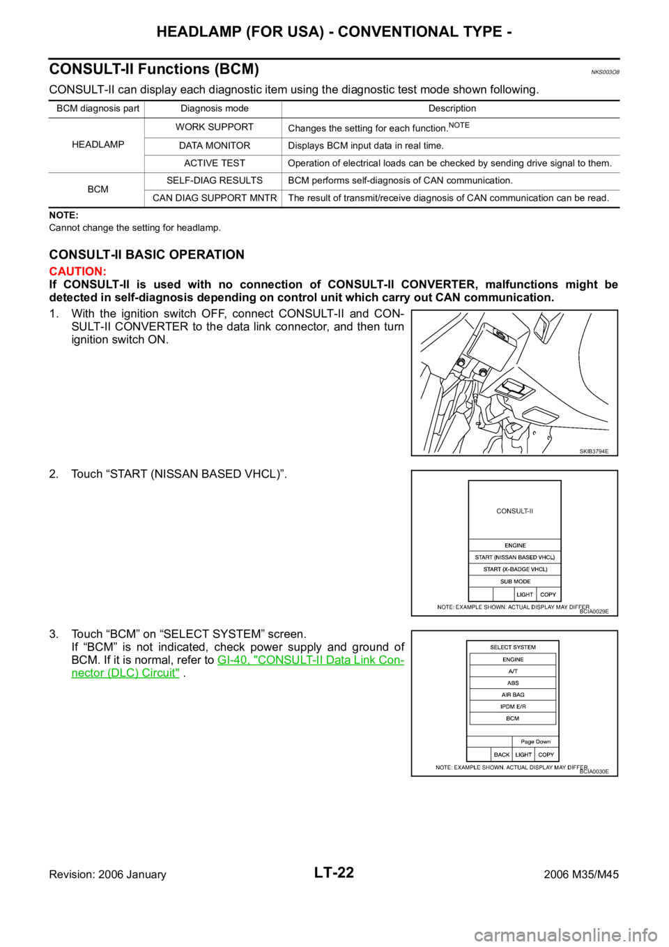
1. With the ignition switch OFF, connect CONSULT-II and CON-
SULT-II CONVERTER to the data link connector, and then turn
ignition switch ON.
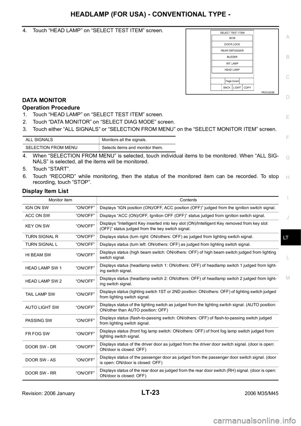
2. Touch “START (NISSAN BASED VHCL)”.
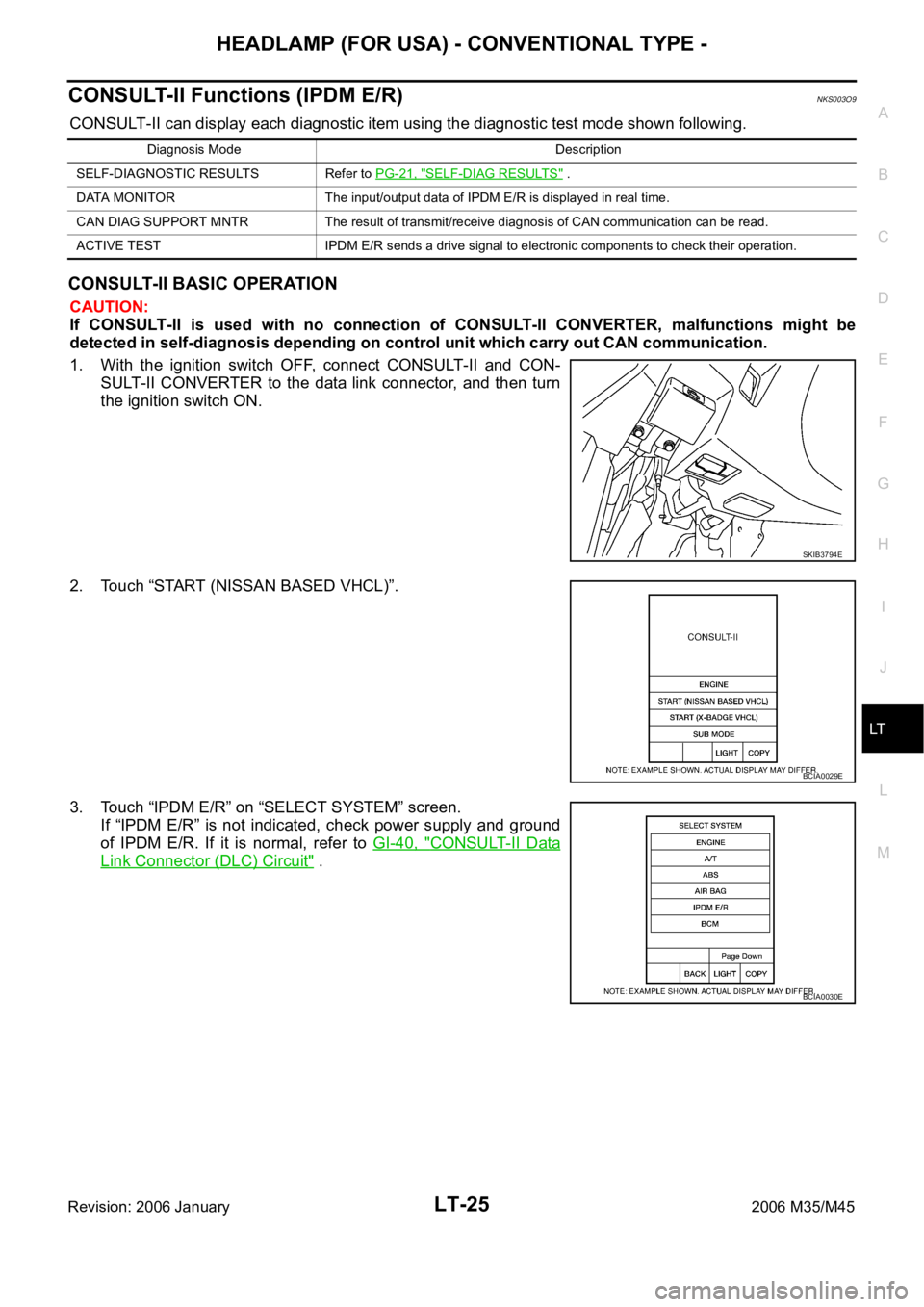
3. Touch “BCM” on “SELECT SYSTEM” screen.
If “BCM” is not indicated, check power supply and ground of
BCM. If it is normal, refer to GI-40, "
CONSULT-II Data Link Con-
nector (DLC) Circuit" .
BCM diagnosis part Diagnosis mode Description
HEADLAMPWORK SUPPORT
Changes the setting for each function.
NOTE
DATA MONITOR Displays BCM input data in real time.
ACTIVE TEST Operation of electrical loads can be checked by sending drive signal to them.
BCMSELF-DIAG RESULTS BCM performs self-diagnosis of CAN communication.
CAN DIAG SUPPORT MNTR The result of transmit/receive diagnosis of CAN communication can be read.
SKIB3794E
BCIA0029E
BCIA0030E
Page 4450 of 5621

HEADLAMP (FOR USA) - CONVENTIONAL TYPE -
LT-23
C
D
E
F
G
H
I
J
L
MA
B
LT
Revision: 2006 January2006 M35/M45
4. Touch “HEAD LAMP” on “SELECT TEST ITEM” screen.
DATA MONITOR
Operation Procedure
1. Touch “HEAD LAMP” on “SELECT TEST ITEM” screen.
2. Touch “DATA MONITOR” on “SELECT DIAG MODE” screen.
3. Touch either “ALL SIGNALS” or “SELECTION FROM MENU” on the “SELECT MONITOR ITEM” screen.
4. When “SELECTION FROM MENU” is selected, touch individual items to be monitored. When “ALL SIG-
NALS” is selected, all the items will be monitored.
5. Touch “START”.
6. Touch “RECORD” while monitoring, then the status of the monitored item can be recorded. To stop
recording, touch “STOP”.
Display Item List
PKIC0325E
ALL SIGNALS Monitors all the signals.
SELECTION FROM MENU Selects items and monitor them.
Monitor item Contents
IGN ON SW “ON/OFF” Displays “IGN position (ON)/OFF, ACC position (OFF)” judged from the ignition switch signal.
ACC ON SW “ON/OFF” Displays “ACC (ON)/OFF, Ignition OFF (OFF)” status judged from ignition switch signal.
KEY ON SW “ON/OFF”Displays “Intelligent Key inserted into key slot (ON)/Intelligent Key removed from key slot
(OFF)” status judged from the key switch signal.
TURN SIGNAL R “ON/OFF” Displays status (turn right: ON/others: OFF) as judged from lighting switch signal.
TURN SIGNAL L “ON/OFF” Displays status (turn left: ON/others: OFF) as judged from lighting switch signal.
HI BEAM SW “ON/OFF”Displays status (high beam switch: ON/others: OFF) of high beam switch judged from lighting
switch signal.
HEAD LAMP SW 1 “ON/OFF”Displays status (headlamp switch 1: ON/others: OFF) of headlamp switch 1 judged from light-
ing switch signal.
HEAD LAMP SW 2 “ON/OFF”Displays status (headlamp switch 2: ON/others: OFF) of headlamp switch 2 judged from light-
ing switch signal.
TAIL LAMP SW “ON/OFF”Displays status (lighting switch 1ST or 2ND position: ON/others: OFF) of lighting switch judged
from lighting switch signal.
AUTO LIGHT SW “ON/OFF”Displays status of the lighting switch as judged from the lighting switch signal. (AUTO position:
ON/other than AUTO position: OFF)
PASSING SW “ON/OFF”Displays status (flash-to-passing switch: ON/others: OFF) of flash-to-passing switch judged
from lighting switch signal.
FR FOG SW “ON/OFF”Displays status (front fog lamp switch: ON/others: OFF) of front fog lamp switch judged from
lighting switch signal.
DOOR SW - DR “ON/OFF”Displays status of the driver door as judged from the driver door switch signal. (door is open:
ON/door is closed: OFF)
DOOR SW - AS “ON/OFF”Displays status of the passenger door as judged from the passenger door switch signal. (door
is open: ON/door is closed: OFF)
DOOR SW - RR “ON/OFF”Displays status of the rear door as judged from the rear door switch (RH) signal. (door is open:
ON/door is closed: OFF)
Page 4451 of 5621

LT-24
HEADLAMP (FOR USA) - CONVENTIONAL TYPE -
Revision: 2006 January2006 M35/M45
NOTE:
This item is displayed, but cannot be monitored.
ACTIVE TEST
Operation Procedure
1. Touch “HEAD LAMP” on “SELECT TEST ITEM” screen.
2. Touch “ACTIVE TEST” on “SELECT DIAG MODE” screen.
3. Touch item to be tested and check operation of the selected item.
4. During the operation check, touching “BACK” deactivates the operation.
Display Item List
NOTE:
This item is displayed, but cannot be tested.DOOR SW - RL “ON/OFF”Displays status of the rear door as judged from the rear door switch (LH) signal. (door is open:
ON/door is closed: OFF)
BACK DOOR SW
NOTE “OFF” —
OPTICAL SENSOR “0 - 5V” Displays “outside brightness (close to 5V when light/close to 0V when dark)” judged from opti-
cal sensor signal.
VEHICLE SPEED “km/h” Displays vehicle speed as judged from vehicle speed signal. Monitor item Contents
Test item Description
TAIL LAMP Allows tail lamp relay to operate by switching ON-OFF.
FR FOG LAMP Allows front fog lamp relay to operate by switching ON-OFF.
DAYTIME RUNNING LIGHT
NOTE—
HEAD LAMP (HI, LO) Allows headlamp relay to operate by switching ON-OFF.
Page 4452 of 5621

HEADLAMP (FOR USA) - CONVENTIONAL TYPE -
LT-25
C
D
E
F
G
H
I
J
L
MA
B
LT
Revision: 2006 January2006 M35/M45
CONSULT-II Functions (IPDM E/R)NKS003O9
CONSULT-II can display each diagnostic item using the diagnostic test mode shown following.
CONSULT-II BASIC OPERATION
CAUTION:
If CONSULT-II is used with no connection of CONSULT-II CONVERTER, malfunctions might be
detected in self-diagnosis depending on control unit which carry out CAN communication.
1. With the ignition switch OFF, connect CONSULT-II and CON-
SULT-II CONVERTER to the data link connector, and then turn
the ignition switch ON.
2. Touch “START (NISSAN BASED VHCL)”.
3. Touch “IPDM E/R” on “SELECT SYSTEM” screen.
If “IPDM E/R” is not indicated, check power supply and ground
of IPDM E/R. If it is normal, refer to GI-40, "
CONSULT-II Data
Link Connector (DLC) Circuit" .
Diagnosis Mode Description
SELF-DIAGNOSTIC RESULTS Refer to PG-21, "
SELF-DIAG RESULTS" .
DATA MONITOR The input/output data of IPDM E/R is displayed in real time.
CAN DIAG SUPPORT MNTR The result of transmit/receive diagnosis of CAN communication can be read.
ACTIVE TEST IPDM E/R sends a drive signal to electronic components to check their operation.
SKIB3794E
BCIA0029E
BCIA0030E