Page 4851 of 5621

PG-24
IPDM E/R (INTELLIGENT POWER DISTRIBUTION MODULE ENGINE ROOM)
Revision: 2006 January2006 M35/M45
Auto Active TestNKS004E7
DESCRIPTION
In auto active test mode, operation inspection can be performed when IPDM E/R sends a drive signal to the
following systems:
Rear window defogger
Front wiper (LO, HI)
Tail lamps, parking lamps and license plate lamps
Front fog lamps
Headlamps (LO, HI)
A/C compressor (magnetic clutch)
Cooling fan
Oil pressure warning lamp
OPERATION PROCEDURE
1. Close hood and front door (passenger side), and then lift wiper arms away from windshield (to prevent
glass damage by wiper operation).
NOTE:
When auto active test is performed with hood opened, sprinkle water on windshield beforehand.
2. Turn ignition switch OFF.
3. Turn ignition switch ON, and within 20 seconds, press driver's door switch 10 times (close other doors).
Then turn ignition switch OFF.
4. Turn ignition switch ON within 10 seconds after ignition switch OFF.
5. When auto active test mode is actuated, horn chirps once. Oil pressure warning lamp starts blinking.
6. After a series of operations is repeated three times, auto active test is completed.
NOTE:
When auto active test mode has to be cancelled halfway, turn ignition switch OFF.
CAUTION:
Never start the engine.
If the engine starting operation is made, delete DTC on the self-diag results of CONSULT-II.
Refer to BL-81, "
CONSULT-II Application Items" .
Be sure to inspect GW-52, "Door Switch Check" when the auto active test cannot be performed.
Page 5014 of 5621

RF-1
ROOF
I BODY
CONTENTS
C
D
E
F
G
H
J
K
L
M
SECTION RF
A
B
RF
Revision: 2006 January2006 M35/M45
ROOF
PRECAUTIONS .......................................................... 2
Precautions for Supplemental Restraint System
(SRS) “AIR BAG” and “SEAT BELT PRE-TEN-
SIONER” .................................................................. 2
Precautions .............................................................. 2
PREPARATION ........................................................... 3
Special Service Tools ............................................... 3
Commercial Service Tools ........................................ 3
SQUEAK AND RATTLE TROUBLE DIAGNOSES ..... 4
Work Flow ................................................................ 4
CUSTOMER INTERVIEW ..................................... 4
DUPLICATE THE NOISE AND TEST DRIVE ....... 5
CHECK RELATED SERVICE BULLETINS ........... 5
LOCATE THE NOISE AND IDENTIFY THE
ROOT CAUSE ...................................................... 5
REPAIR THE CAUSE ........................................... 5
CONFIRM THE REPAIR ....................................... 6
Generic Squeak and Rattle Troubleshooting ........... 6
INSTRUMENT PANEL .......................................... 6
CENTER CONSOLE ............................................. 6
DOORS ................................................................. 6
TRUNK .................................................................. 7
SUNROOF/HEADLINING ..................................... 7
SEATS ................................................................... 7
UNDERHOOD ....................................................... 7
Diagnostic Worksheet .............................................. 8
SUNROOF ................................................................ 10
Component Parts and Harness Connector Location ... 10
System Description ................................................. 11
TILT UP / SLIDE CLOSE OPERATION ................ 11TILT DOWN / SLIDE OPEN OPERATION .......... 11
AUTO OPERATION ............................................. 11
RETAINED POWER OPERATION ...................... 11
ANTI-PINCH FUNCTION .................................... 12
INITIALIZATION PROCEDURE .......................... 12
Wiring Diagram — SROOF — ................................ 13
Terminals and Reference Value for BCM ............... 15
Terminals and Reference Value for Sunroof Motor
Assembly ................................................................ 15
CONSULT-II Function (BCM) ................................. 16
ACTIVE TEST ..................................................... 17
WORK SUPPORT ............................................... 17
DATE MONITOR ................................................. 17
Work Flow ............................................................... 18
Diagnosis Symptom Chart ...................................... 18
BCM Power Supply and Ground Circuit Check ...... 18
Sunroof Motor Assembly Power Supply and Ground
Circuit Check .......................................................... 19
Sunroof Switch Check .........................................
... 21
Door Switch Check ..............................................
... 23
Fitting Adjustment ................................................... 25
RID WEATHERSTRIP OVERLAP ADJUST-
MENT AND SURFACE MISMATCH ADJUST-
MENT .................................................................. 25
Removal and Installation ........................................ 25
SUNROOF UNIT ................................................. 27
Disassembly and Assembly .................................... 28
DISASSEMBLY ................................................... 29
ASSEMBLY ......................................................... 29
Page 5609 of 5621

WW-42
FRONT WIPER AND WASHER SYSTEM
Revision: 2006 January2006 M35/M45
Removal and Installation of Front Wiper Arms, Adjustment of Wiper Arms Stop
Location
NKS003WY
REMOVAL
1. Turn wiper switch ON to operate wiper motor, and then turn wiper switch OFF (auto stop).
2. Open hood, remove arm caps, and remove wiper arm nuts.
3. Raise wiper arm, and remove wiper arm from the vehicle.
INSTALLATION
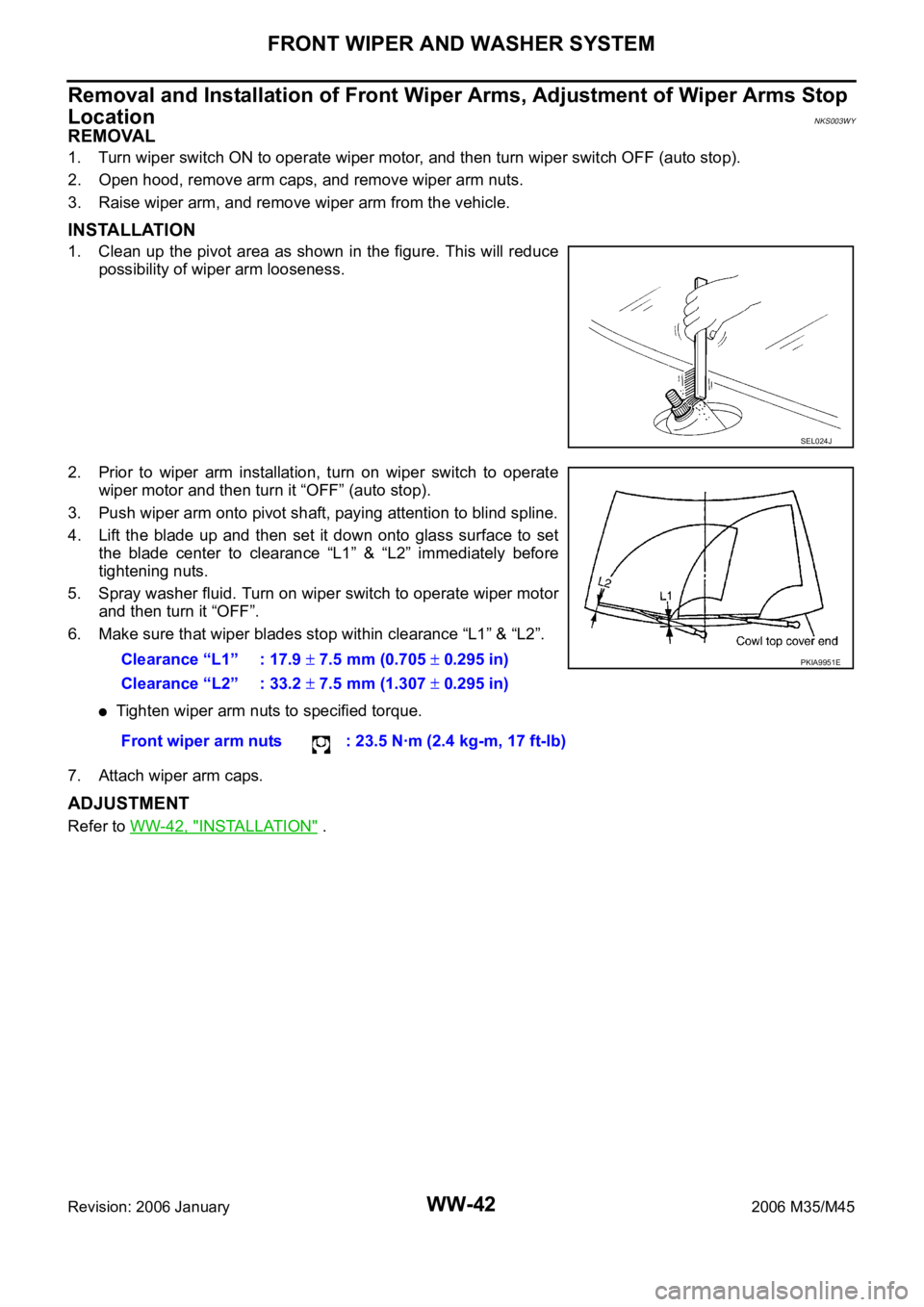
1. Clean up the pivot area as shown in the figure. This will reduce
possibility of wiper arm looseness.
2. Prior to wiper arm installation, turn on wiper switch to operate
wiper motor and then turn it “OFF” (auto stop).
3. Push wiper arm onto pivot shaft, paying attention to blind spline.
4. Lift the blade up and then set it down onto glass surface to set
the blade center to clearance “L1” & “L2” immediately before
tightening nuts.
5. Spray washer fluid. Turn on wiper switch to operate wiper motor
and then turn it “OFF”.
6. Make sure that wiper blades stop within clearance “L1” & “L2”.
Tighten wiper arm nuts to specified torque.
7. Attach wiper arm caps.
ADJUSTMENT
Refer to WW-42, "INSTALLATION" .
SEL024J
Clearance “L1” : 17.9 7.5 mm (0.705 0.295 in)
Clearance “L2” : 33.2
7.5 mm (1.307 0.295 in)
Front wiper arm nuts : 23.5 Nꞏm (2.4 kg-m, 17 ft-lb)
PKIA9951E
Page 5612 of 5621
FRONT WIPER AND WASHER SYSTEM
WW-45
C
D
E
F
G
H
I
J
L
MA
B
WW
Revision: 2006 January2006 M35/M45
Washer Tube LayoutNKS003X2
Removal and Installation of Front Washer NozzleNKS003X3
REMOVAL
1. Open hood, and turn off the washer hose seal rubber.
2. While pushing nozzle spray point side along body, use the noz-
zle stop point as the support point and rotate nozzle (1) to
remove it from body.
3. Remove washer tube (2).
INSTALLATION
1. Install washer tube in nozzle.
2. Install nozzle to the vehicle.
3. Adjust nozzle spray location. Refer to WW-44, "
Washer Nozzle Adjustment" .
CAUTION:
The spray points differ, so be sure to install left and right nozzles correctly.
SKIB4253E
SKIB4255E