2006 INFINITI M35 belt
[x] Cancel search: beltPage 1435 of 5621

DI-2Revision: 2006 January2006 M35/M45 A/T INDICATOR ........................................................ 56
System Description ................................................. 56
MANUAL MODE .................................................. 56
NOT MANUAL MODE ......................................... 56
Wiring Diagram — AT/IND — ................................. 57
A/T Indicator Is Malfunction .................................... 59
WARNING CHIME .................................................. ... 60
System Description ................................................. 60
POWER SUPPLY AND GROUND CIRCUIT ....... 60
IGNITION KEY WARNING CHIME (WITH INTEL-
LIGENT KEY) ...................................................... 61
LIGHT WARNING CHIME ................................... 61
SEAT BELT WARNING CHIME ........................... 61
Component Parts and Harness Connector Location ... 62
Schematic ............................................................... 63
Wiring Diagram — CHIME — ................................. 64
Terminals and Reference Value for Combination
Meter ...................................................................... 67
Terminals and Reference Value for Unified Meter
and A/C Amp. ......................................................... 67
Terminals and Reference Value for BCM ................ 68
CONSULT-II Function (BCM) .................................. 69
CONSULT-II BASIC OPERATION ....................... 69
DATA MONITOR .................................................. 70
ACTIVE TEST ..................................................... 71
SELF-DIAG RESULTS ........................................ 71
CONSULT-II Function (METER A/C AMP) ............. 71
Trouble Diagnosis ................................................... 71
HOW TO PERFORM TROUBLE DIAGNOSIS .... 71
PRELIMINARY INSPECTION ............................. 71
SYMPTOM CHART ............................................. 72
Meter Buzzer Circuit Inspection .............................. 72
Lighting Switch Signal Inspection ........................... 73
Front Door Switch (Driver Side) Signal Inspection ... 73
Seat Belt Buckle Switch Signal Inspection ............. 74
Electrical Component Inspection ............................ 76
FRONT DOOR SWITCH (DRIVER SIDE) ........... 76
SEAT BELT BUCKLE SWITCH (DRIVER SIDE) ... 76
CAN COMMUNICATION ........................................... 77
System Description ................................................. 77
CAN Communication Unit ....................................... 77
LANE DEPARTURE WARNING SYSTEM ................ 78
Precautions for Lane Departure Warning (LDW)
system .................................................................... 78
System Description ................................................. 78
LDW SYSTEM OPERATION ............................... 78
POWER SUPPLY AND GROUND CIRCUIT ....... 80
Action Test ...........................................................
... 80
LDW SYSTEM RUNNING TEST ......................... 80
Camera Aiming Adjustment .................................... 81
OUTLINE ............................................................. 81
PREPARATION ................................................... 81TARGET SETTING .............................................. 81
VEHICLE HEIGHT CHECK ................................. 84
AIMING ADJUSTMENT ....................................... 84
Component Parts and Harness Connector Location ... 88
Wiring Diagram — LDW — ..................................... 89
Terminals and Reference Value for LDW Camera
Unit .......................................................................... 91
CONSULT-II Function (LDW) .................................. 91
DESCRIPTION .................................................... 91
CONSULT-II BASIC OPERATION ....................... 91
WORK SUPPORT ............................................... 92
SELF-DIAG RESULTS ......................................... 92
DATA MONITOR .................................................. 93
ACTIVE TEST ...................................................... 94
Trouble Diagnosis ................................................... 95
HOW TO PERFORM TROUBLE DIAGNOSIS .... 95
PRELIMINARY INSPECTION .............................. 95
SYMPTOM CHART .............................................. 96
Power Supply and Ground Circuit Inspection ......... 96
DTC [C1B00] CAMERA UNIT MALF ...................... 97
DTC [C1B01] CAM AIMING INCMP ....................... 97
DTC [C1B02] VHCL SPD DATA MALF ................... 97
DTC [C1B03] ABNRML TEMP DETECT ................ 97
DTC [U1000] CAN COMM CIRCUIT ...................... 98
DTC [U1010] CONTROL UNIT (CAN) .................... 98
LDW Chime Circuit Inspection ................................ 98
LDW Switch Circuit Inspection ................................ 99
LDW Indicator Lamp Circuit Inspection .................102
Turn Signal Input Inspection .................................103
Electrical Component Inspection ..........................103
LDW SWITCH ....................................................103
Removal and Installation for LDW Camera Unit ...103
REMOVAL ..........................................................103
INSTALLATION ..................................................103
Removal and Installation for LDW Chime .............104
REMOVAL ..........................................................104
INSTALLATION ..................................................104
Removal and Installation for LDW Switch .............104
COMPASS ...............................................................105
System Description ...............................................105
DIRECTION DISPLAY .......................................105
Zone Variation Change Procedure ........................105
Correction Functions of the Compass Display ......105
AUTOMATIC CORRECTION .............................105
MANUAL CORRECTION PROCEDURE ...........105
Wiring Diagram – COMPAS – ...............................106
Removal and Installation of Compass ...................107
CLOCK ....................................................................108
Wiring Diagram — CLOCK — ...............................108
Removal and Installation of Clock .........................109
REMOVAL ..........................................................109
INSTALLATION ..................................................109
Page 1436 of 5621

PRECAUTION
DI-3
C
D
E
F
G
H
I
J
L
MA
B
DI
Revision: 2006 January2006 M35/M45
PRECAUTION PFP:00011
Precautions for Supplemental Restraint System (SRS) “AIR BAG” and “SEAT
BELT PRE-TENSIONER”
NKS003TT
The Supplemental Restraint System such as “AIR BAG” and “SEAT BELT PRE-TENSIONER”, used along
with a front seat belt, helps to reduce the risk or severity of injury to the driver and front passenger for certain
types of collision. This system includes seat belt switch inputs and dual stage front air bag modules. The SRS
system uses the seat belt switches to determine the front air bag deployment, and may only deploy one front
air bag, depending on the severity of a collision and whether the front occupants are belted or unbelted.
Information necessary to service the system safely is included in the SRS and SB section of this Service Man-
ual.
WAR NING :
To avoid rendering the SRS inoperative, which could increase the risk of personal injury or death
in the event of a collision which would result in air bag inflation, all maintenance must be per-
formed by an authorized NISSAN/INFINITI dealer.
Improper maintenance, including incorrect removal and installation of the SRS, can lead to per-
sonal injury caused by unintentional activation of the system. For removal of Spiral Cable and Air
Bag Module, see the SRS section.
Do not use electrical test equipment on any circuit related to the SRS unless instructed to in this
Service Manual. SRS wiring harnesses can be identified by yellow and/or orange harnesses or
harness connectors.
Page 1466 of 5621
UNIFIED METER AND A/C AMP
DI-33
C
D
E
F
G
H
I
J
L
MA
B
DI
Revision: 2006 January2006 M35/M45
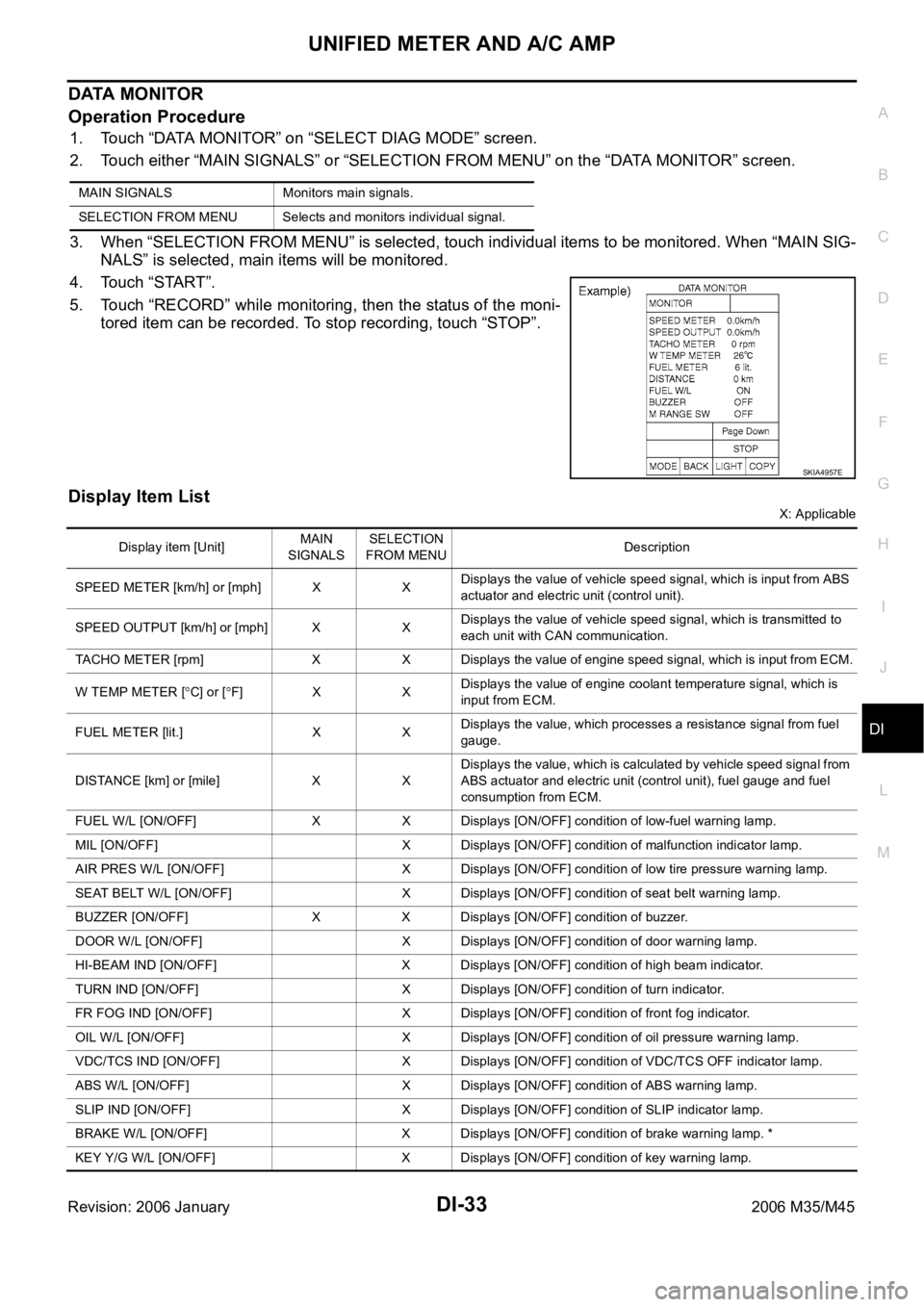
DATA MONITOR
Operation Procedure
1. Touch “DATA MONITOR” on “SELECT DIAG MODE” screen.
2. Touch either “MAIN SIGNALS” or “SELECTION FROM MENU” on the “DATA MONITOR” screen.
3. When “SELECTION FROM MENU” is selected, touch individual items to be monitored. When “MAIN SIG-
NALS” is selected, main items will be monitored.
4. Touch “START”.
5. Touch “RECORD” while monitoring, then the status of the moni-
tored item can be recorded. To stop recording, touch “STOP”.
Display Item List
X: Applicable MAIN SIGNALS Monitors main signals.
SELECTION FROM MENU Selects and monitors individual signal.
SKIA4957E
Display item [Unit]MAIN
SIGNALSSELECTION
FROM MENUDescription
SPEED METER [km/h] or [mph] X XDisplays the value of vehicle speed signal, which is input from ABS
actuator and electric unit (control unit).
SPEED OUTPUT [km/h] or [mph] X XDisplays the value of vehicle speed signal, which is transmitted to
each unit with CAN communication.
TACHO METER [rpm] X X Displays the value of engine speed signal, which is input from ECM.
W TEMP METER [
C] or [F] X XDisplays the value of engine coolant temperature signal, which is
input from ECM.
FUEL METER [lit.] X XDisplays the value, which processes a resistance signal from fuel
gauge.
DISTANCE [km] or [mile] X XDisplays the value, which is calculated by vehicle speed signal from
ABS actuator and electric unit (control unit), fuel gauge and fuel
consumption from ECM.
FUEL W/L [ON/OFF] X X Displays [ON/OFF] condition of low-fuel warning lamp.
MIL [ON/OFF] X Displays [ON/OFF] condition of malfunction indicator lamp.
AIR PRES W/L [ON/OFF] X Displays [ON/OFF] condition of low tire pressure warning lamp.
SEAT BELT W/L [ON/OFF] X Displays [ON/OFF] condition of seat belt warning lamp.
BUZZER [ON/OFF] X X Displays [ON/OFF] condition of buzzer.
DOOR W/L [ON/OFF] X Displays [ON/OFF] condition of door warning lamp.
HI-BEAM IND [ON/OFF] X Displays [ON/OFF] condition of high beam indicator.
TURN IND [ON/OFF] X Displays [ON/OFF] condition of turn indicator.
FR FOG IND [ON/OFF] X Displays [ON/OFF] condition of front fog indicator.
OIL W/L [ON/OFF] X Displays [ON/OFF] condition of oil pressure warning lamp.
VDC/TCS IND [ON/OFF] X Displays [ON/OFF] condition of VDC/TCS OFF indicator lamp.
ABS W/L [ON/OFF] X Displays [ON/OFF] condition of ABS warning lamp.
SLIP IND [ON/OFF] X Displays [ON/OFF] condition of SLIP indicator lamp.
BRAKE W/L [ON/OFF] X Displays [ON/OFF] condition of brake warning lamp. *
KEY Y/G W/L [ON/OFF] X Displays [ON/OFF] condition of key warning lamp.
Page 1494 of 5621

WARNING CHIME
DI-61
C
D
E
F
G
H
I
J
L
MA
B
DI
Revision: 2006 January2006 M35/M45
IGNITION KEY WARNING CHIME (WITH INTELLIGENT KEY)
Refer to BL-55, "WARNING FUNCTION" in intelligent key system.
LIGHT WARNING CHIME
With ignition switch in OFF or ACC position, driver door open, and lighting switch in 1ST or 2ND position, the
light warning chime will sound.
BCM detects ignition switch in OFF or ACC position, front door switch (driver side) ON, and lighting switch
in 1ST or 2ND position. And then transmits buzzer output signal (light warning chime) to unified meter and
A/C amp. with CAN communication line.
Unified meter and A/C amp. transmits buzzer output signal (light warning chime) to combination meter
with communication line.
When combination meter receives buzzer output signal (light warning chime), it sounds the buzzer.
NOTE:
For further details of combination switch, refer to BCS-3, "
COMBINATION SWITCH READING FUNCTION" .
SEAT BELT WARNING CHIME
With ignition switch turned ON and driver seat belt unfastened, seat belt warning chime will sound for approxi-
mately 6 seconds.
BCM receives seat belt buckle switch signal [seat belt buckle switch (driver side) ON] from unified meter
and A/C amp. with CAN communication line.
BCM detects ignition switch turned ON and seat belt buckle switch (driver side) ON. And then transmits
buzzer output signal (seat belt warning chime) to unified meter and A/C amp. with CAN communication
line.
Unified meter and A/C amp. transmits buzzer output signal (seat belt warning chime) to combination
meter with communication line.
When combination meter receives buzzer output signal (seat belt warning chime), it sounds the buzzer.
SKIB3858E
SKIB3859E
Page 1500 of 5621
WARNING CHIME
DI-67
C
D
E
F
G
H
I
J
L
MA
B
DI
Revision: 2006 January2006 M35/M45
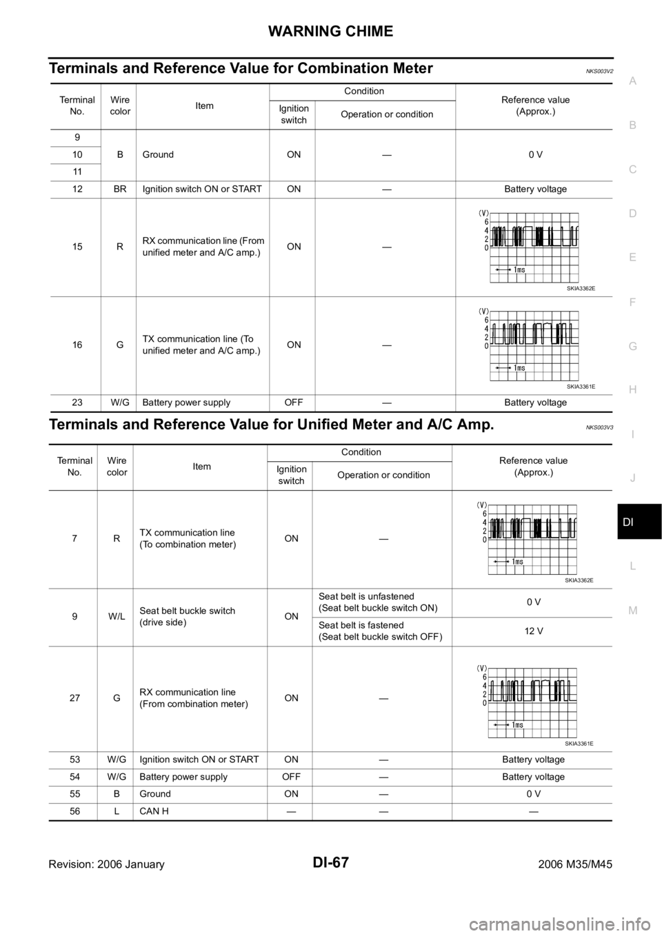
Terminals and Reference Value for Combination MeterNKS003V2
Terminals and Reference Value for Unified Meter and A/C Amp.NKS003V3
Te r m i n a l
No.Wire
colorItemCondition
Reference value
(Approx.) Ignition
switchOperation or condition
9
B Ground ON — 0 V 10
11
12 BR Ignition switch ON or START ON — Battery voltage
15 RRX communication line (From
unified meter and A/C amp.)ON —
16 GTX communication line (To
unified meter and A/C amp.)ON —
23 W/G Battery power supply OFF — Battery voltage
SKIA3362E
SKIA3361E
Terminal
No.Wire
colorItemCondition
Reference value
(Approx.) Ignition
switchOperation or condition
7RTX communication line
(To combination meter)ON —
9W/LSeat belt buckle switch
(drive side)ONSeat belt is unfastened
(Seat belt buckle switch ON)0 V
Seat belt is fastened
(Seat belt buckle switch OFF)12 V
27 GRX communication line
(From combination meter)ON —
53 W/G Ignition switch ON or START ON — Battery voltage
54 W/G Battery power supply OFF — Battery voltage
55 B Ground ON — 0 V
56 L CAN H — — —
SKIA3362E
SKIA3361E
Page 1503 of 5621
DI-70
WARNING CHIME
Revision: 2006 January2006 M35/M45
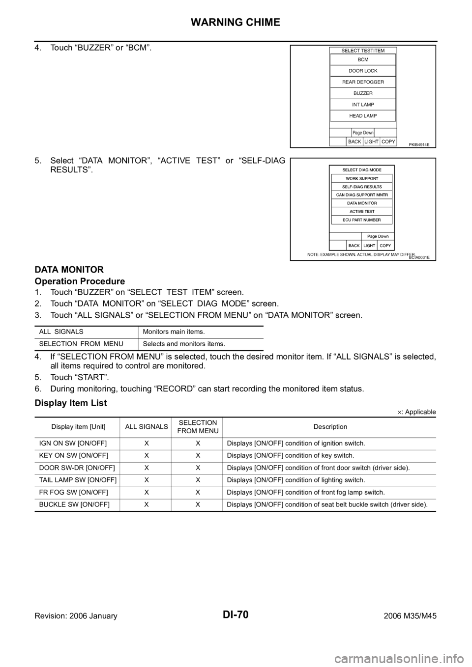
4. Touch “BUZZER” or “BCM”.
5. Select “DATA MONITOR”, “ACTIVE TEST” or “SELF-DIAG
RESULTS”.
DATA MONITOR
Operation Procedure
1. Touch “BUZZER” on “SELECT TEST ITEM” screen.
2. Touch “DATA MONITOR” on “SELECT DIAG MODE” screen.
3. Touch “ALL SIGNALS” or “SELECTION FROM MENU” on “DATA MONITOR” screen.
4. If “SELECTION FROM MENU” is selected, touch the desired monitor item. If “ALL SIGNALS” is selected,
all items required to control are monitored.
5. Touch “START”.
6. During monitoring, touching “RECORD” can start recording the monitored item status.
Display Item List
: Applicable
PKIB4914E
BCIA0031E
ALL SIGNALS Monitors main items.
SELECTION FROM MENU Selects and monitors items.
Display item [Unit] ALL SIGNALSSELECTION
FROM MENUDescription
IGN ON SW [ON/OFF] X X Displays [ON/OFF] condition of ignition switch.
KEY ON SW [ON/OFF] X X Displays [ON/OFF] condition of key switch.
DOOR SW-DR [ON/OFF] X X Displays [ON/OFF] condition of front door switch (driver side).
TAIL LAMP SW [ON/OFF] X X Displays [ON/OFF] condition of lighting switch.
FR FOG SW [ON/OFF] X X Displays [ON/OFF] condition of front fog lamp switch.
BUCKLE SW [ON/OFF] X X Displays [ON/OFF] condition of seat belt buckle switch (driver side).
Page 1504 of 5621
WARNING CHIME
DI-71
C
D
E
F
G
H
I
J
L
MA
B
DI
Revision: 2006 January2006 M35/M45
ACTIVE TEST
Operation Procedure
1. Touch “BUZZER” on “SELECT TEST ITEM” screen.
2. Touch “ACTIVE TEST” on “SELECT DIAG MODE” screen.
3. Touch the item to be tested, and check the operation.
4. During the operation check, touching “OFF” deactivates the operation.
Display Item List
SELF-DIAG RESULTS
Operation Procedure
1. Touch “BCM” on “SELECT TEST ITEM” screen.
2. Touch “SELF-DIAG RESULTS” on “SELECT DIAG MODE” screen.
3. Self-diagnosis results are displayed.
Display Item List
NOTE:
If “CAN communication [U1000]” is indicated, after printing the monitor item, go to “LAN system”. Refer to
LAN-7, "
Precautions When Using CONSULT-II" .
CONSULT-II Function (METER A/C AMP)NKS003V6
CONSULT-II can display each diagnostic item using the diagnostic test modes shown following.
NOTE:
For the further details, refer to DI-71, "
CONSULT-II Function (METER A/C AMP)" .
Trouble DiagnosisNKS003V7
HOW TO PERFORM TROUBLE DIAGNOSIS
1. Confirm the symptom and customer complaint.
2. Understand the outline of system. Refer to DI-60, "
System Description" .
3. Perform the preliminary inspection. Refer to DI-71, "
PRELIMINARY INSPECTION" .
4. Referring to trouble diagnosis chart, make sure the cause of the malfunction and repair or replace applica-
ble parts. Refer to DI-72, "
SYMPTOM CHART" .
5. Does warning chime system operate normally? If yes, GO TO 6. If no, GO TO 3.
6. INSPECTION END
PRELIMINARY INSPECTION
1. CHECK BCM (CONSULT-II)
Perform self-diagnosis of BCM. Refer to BCS-13, "
CONSULT-II Function (BCM)" .
Self
-diagnostic results content
No malfunction detected>> GO TO 2.
Malfunction detected>> Check applicable parts, and repair or replace corresponding parts.
Display item Description
LIGHT WARN ALM This test is able to check light warning chime operation.
IGN KEY WARN ALM This test is able to check key warning chime operation.
SEAT BELT WARN TEST This test is able to check seat belt warning chime operation.
Display item [Code] Malfunction is detected when...
CAN communication [U1000] Malfunction is detected in CAN communication.
System Diagnosis mode DescriptionReference
page
METER A/C
AMPSELF-DIAG RESULTSUnified meter and A/C amp. checks the conditions and displays
memorized error.DI-32
DATA MONITOR Displays unified meter and A/C amp. input data in real time.DI-33
Page 1505 of 5621
DI-72
WARNING CHIME
Revision: 2006 January2006 M35/M45
2. CHECK UNIFIED METER AND A/C AMP. (CONSULT-II)
Perform self-diagnosis of unified meter and A/C amp. Refer to DI-71, "
CONSULT-II Function (METER A/C
AMP)" .
Self
-diagnostic results content
No malfunction detected>> INSPECTION END
Malfunction detected>> Check applicable parts, and repair or replace corresponding parts.
SYMPTOM CHART
Meter Buzzer Circuit InspectionNKS003V8
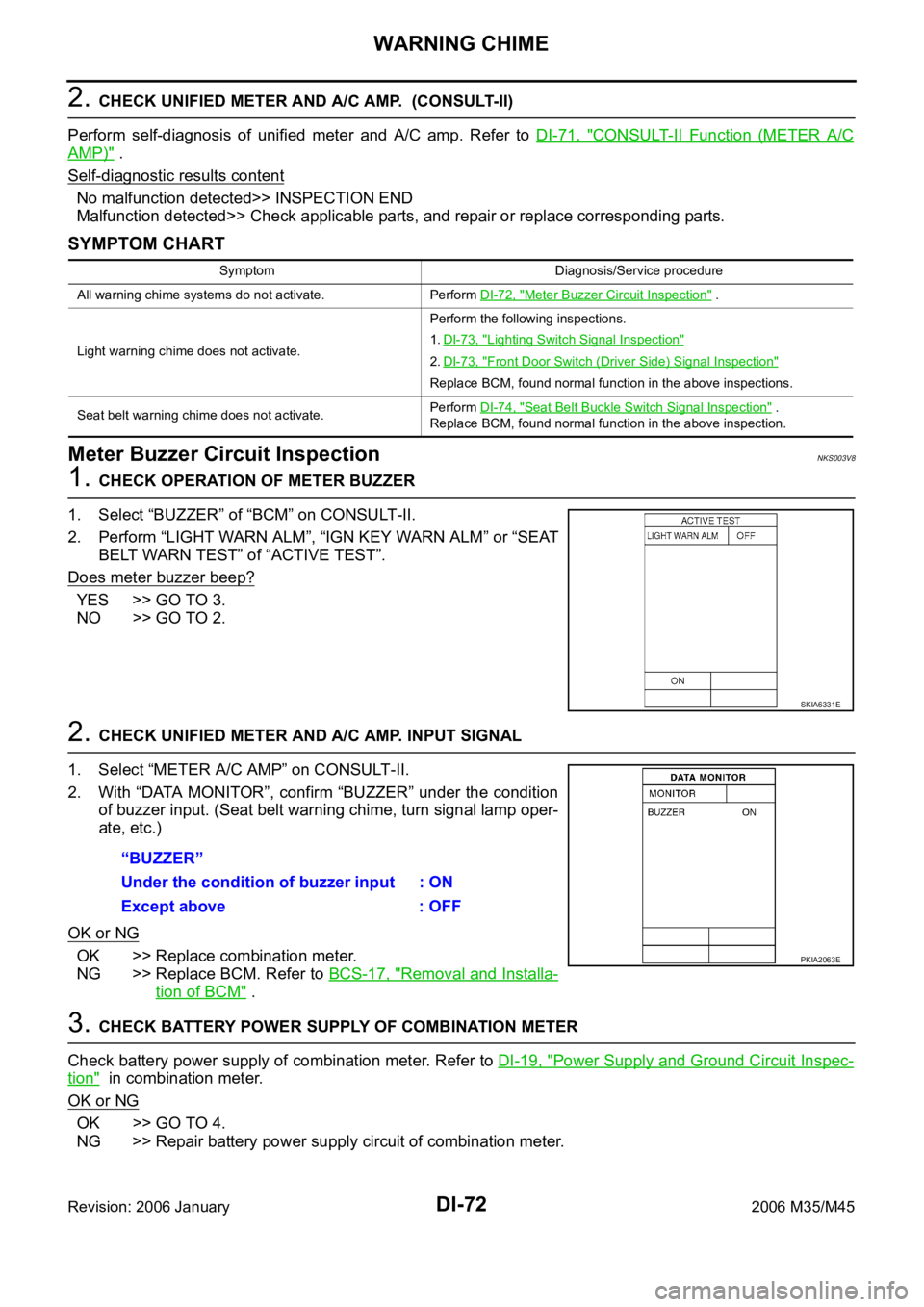
1. CHECK OPERATION OF METER BUZZER
1. Select “BUZZER” of “BCM” on CONSULT-II.
2. Perform “LIGHT WARN ALM”, “IGN KEY WARN ALM” or “SEAT
BELT WARN TEST” of “ACTIVE TEST”.
Does meter buzzer beep?
YES >> GO TO 3.
NO >> GO TO 2.
2. CHECK UNIFIED METER AND A/C AMP. INPUT SIGNAL
1. Select “METER A/C AMP” on CONSULT-II.
2. With “DATA MONITOR”, confirm “BUZZER” under the condition
of buzzer input. (Seat belt warning chime, turn signal lamp oper-
ate, etc.)
OK or NG
OK >> Replace combination meter.
NG >> Replace BCM. Refer to BCS-17, "
Removal and Installa-
tion of BCM" .
3. CHECK BATTERY POWER SUPPLY OF COMBINATION METER
Check battery power supply of combination meter. Refer to DI-19, "
Power Supply and Ground Circuit Inspec-
tion" in combination meter.
OK or NG
OK >> GO TO 4.
NG >> Repair battery power supply circuit of combination meter.
Symptom Diagnosis/Service procedure
All warning chime systems do not activate. Perform DI-72, "
Meter Buzzer Circuit Inspection" .
Light warning chime does not activate.Perform the following inspections.
1.DI-73, "
Lighting Switch Signal Inspection"
2.DI-73, "Front Door Switch (Driver Side) Signal Inspection"
Replace BCM, found normal function in the above inspections.
Seat belt warning chime does not activate.Perform DI-74, "
Seat Belt Buckle Switch Signal Inspection" .
Replace BCM, found normal function in the above inspection.
SKIA6331E
“BUZZER”
Under the condition of buzzer input : ON
Except above : OFF
PKIA2063E