2006 INFINITI M35 belt
[x] Cancel search: beltPage 930 of 5621

BCM (BODY CONTROL MODULE)
BCS-9
C
D
E
F
G
H
I
J
L
MA
B
BCS
Revision: 2006 January2006 M35/M45
MAJOR COMPONENTS AND CONTROL SYSTEM
NOTE:
*1: Functions only when the Intelligent Key is inserted in key slot.
*2: With navigation system
*3: Without navigation systemSystem Input Output
Intelligent Key system Intelligent Key unit
All door locking actuator
Trunk lid opener actuator
Turn signal lamp (LH, RH)
Combination meter
Power door lock system
Power window main switch (door lock and unlock switch)
Power window sub switch (passenger side)
(door lock and unlock switch)All-door locking actuator
Power supply (IGN) to power win-
dow, sunroofIgnition power supply Power window and sunroof system
Power supply (BAT) to power
window, sunroof and power seatBattery power supplyPower window, sunroof system and
power seat
Panic alarm
Key slot
Intelligent KeyIPDM E/R
Theft warning system
All-door switch
Hood switch
Intelligent Key
Power window main switch (door lock and unlock switch)
IPDM E/R
Security indicator lamp
Auto light system
Optical sensor
Combination switchIPDM E/R
Battery saver control
Ignition switch
Combination switchIPDM E/R
Headlamp
Tail lamp
Front fog lampCombination switch IPDM E/R
Turn signal lamp Combination switch
Turn signal lamp
Combination meter
Hazard lamp Hazard switch
Turn signal lamp
Combination meter
Room lamp timer
Key switch
Power window main switch (door lock and unlock switch)
Front door switch driver side
All-door switchInterior room lamp
Key warning chime*
1Key switch
Front door switch driver sideCombination meter (warning buzzer)
Light warning chime
Combination switch
Front door switch driver sideCombination meter (warning buzzer)
Seat belt warning chime
Combination meter [Seat belt buckle (driver side) switch]
Ignition switchCombination meter (warning buzzer)
Vehicle-speed-sensing intermit-
tent wiper
Combination switch
Unified meter and A/C amp.IPDM E/R
Rear window defogger
Multifunction switch
NAVI control unit*2
AV control unit*3
IPDM E/R
Page 940 of 5621

BL-1
BODY, LOCK & SECURITY SYSTEM
I BODY
CONTENTS
C
D
E
F
G
H
J
K
L
M
SECTION BL
A
B
BL
Revision: 2006 January2006 M35/M45
BODY, LOCK & SECURITY SYSTEM
PRECAUTIONS .......................................................... 6
Precautions for Supplemental Restraint System
(SRS) “AIR BAG” and “SEAT BELT PRE-TEN-
SIONER” .................................................................. 6
Precautions for Procedures without Cowl Top Cover ..... 6
Precautions Necessary for Steering Wheel Rotation
after Battery Disconnect ........................................... 6
OPERATION PROCEDURE ................................. 6
Precautions for Work ...........................................
..... 7
PREPARATION ........................................................... 8
Special Service Tools ............................................... 8
Commercial Service Tools ........................................ 8
SQUEAK AND RATTLE TROUBLE DIAGNOSIS ...... 9
Work Flow ................................................................ 9
CUSTOMER INTERVIEW ..................................... 9
DUPLICATE THE NOISE AND TEST DRIVE ..... 10
CHECK RELATED SERVICE BULLETINS ......... 10
LOCATE THE NOISE AND IDENTIFY THE
ROOT CAUSE .................................................... 10
REPAIR THE CAUSE ......................................... 10
CONFIRM THE REPAIR ...................................... 11
Generic Squeak and Rattle Troubleshooting .......... 11
INSTRUMENT PANEL ......................................... 11
CENTER CONSOLE ............................................ 11
DOORS ................................................................ 11
TRUNK ................................................................ 12
SUNROOF/HEADLINING ................................... 12
SEATS ................................................................. 12
UNDERHOOD ..................................................... 12
Diagnostic Worksheet ............................................ 13
HOOD ....................................................................... 15
Fitting Adjustment .................................................. 15
Removal and Installation of Hood Assembly .......... 17
REMOVAL ........................................................
... 17
INSTALLETION ................................................... 18
Removal and Installation of Hood Lock Control ..... 18
REMOVAL ........................................................
... 18
INSTALLATION ................................................... 19
Hood Lock Control Inspection ................................ 20RADIATOR CORE SUPPORT .................................. 21
Removal and Installation ........................................ 21
REMOVAL ........................................................
... 21
INSTALLATION ................................................... 22
FRONT FENDER ................................................... ... 23
Removal and Installation ........................................ 23
REMOVAL ........................................................
... 23
INSTALLATION ................................................... 23
POWER DOOR LOCK SYSTEM .............................. 24
Component Parts and Harness Connector Location ... 24
System Description ................................................. 25
DOOR LOCK ACTUATOR OPERATION ............. 26
FUEL LID OPERATION ....................................... 26
OUTLINE ............................................................. 26
CAN Communication System Description .............. 26
CAN Communication Unit ....................................... 26
Schematic ............................................................... 27
Wiring Diagram —D/LOCK— ................................. 28
Terminals and Reference Value of BCM ................. 31
Work Flow ............................................................... 31
CONSULT-II Function (BCM) ................................. 32
CONSULT-II INSPECTION PROCEDURE .......... 32
CONSULT-II APPLICATION ITEMS .................... 33
Trouble Diagnosis Chart by Symptom .................... 34
Power Supply and Ground Circuit Check of BCM ... 35
Check Door Lock and Unlock Switch ..................... 36
Check Door Lock Actuator/Driver Side ................... 38
Check Door Lock Actuator/Passenger Side ........... 39
Check Door Lock Actuator/Rear LH ....................... 40
Check Door Lock Actuator/Rear RH ....................... 40
Check Fuel Lid Opener Actuator ............................ 41
Door Key Cylinder Switch Check ............................ 42
INTELLIGENT KEY SYSTEM ................................... 44
Component Parts and Harness Connector Location ... 44
System Description ................................................. 48
DOOR LOCK/UNLOCK/TRUNK OPEN FUNC-
TION .................................................................... 48
REMOTE KEYLESS ENTRY FUNCTIONS ......... 52
ENGINE START FUNCTION ............................... 54
WARNING FUNCTION ........................................ 55
Page 945 of 5621

BL-6
PRECAUTIONS
Revision: 2006 January2006 M35/M45
PRECAUTIONSPFP:00001
Precautions for Supplemental Restraint System (SRS) “AIR BAG” and “SEAT
BELT PRE-TENSIONER”
NIS001WA
The Supplemental Restraint System such as “AIR BAG” and “SEAT BELT PRE-TENSIONER”, used along
with a front seat belt, helps to reduce the risk or severity of injury to the driver and front passenger for certain
types of collision. This system includes seat belt switch inputs and dual stage front air bag modules. The SRS
system uses the seat belt switches to determine the front air bag deployment, and may only deploy one front
air bag, depending on the severity of a collision and whether the front occupants are belted or unbelted.
Information necessary to service the system safely is included in the SRS and SB section of this Service Man-
ual.
WAR NING :
To avoid rendering the SRS inoperative, which could increase the risk of personal injury or death
in the event of a collision which would result in air bag inflation, all maintenance must be per-
formed by an authorized NISSAN/INFINITI dealer.
Improper maintenance, including incorrect removal and installation of the SRS, can lead to per-
sonal injury caused by unintentional activation of the system. For removal of Spiral Cable and Air
Bag Module, see the SRS section.
Do not use electrical test equipment on any circuit related to the SRS unless instructed to in this
Service Manual. SRS wiring harnesses can be identified by yellow and/or orange harnesses or
harness connectors.
Precautions for Procedures without Cowl Top CoverNIS001WB
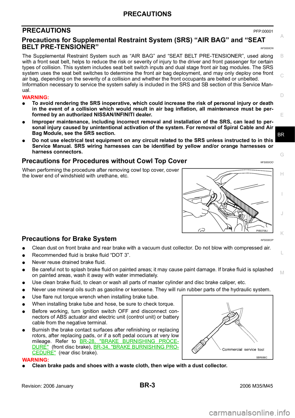
When performing the procedure after removing cowl top cover, cover
the lower end of windshield with urethane, etc.
Precautions Necessary for Steering Wheel Rotation after Battery DisconnectNIS001WC
NOTE:
Before removing and installing any control units, first turn the push-button ignition switch to the LOCK
position, then disconnect both battery cables.
After finishing work, confirm that all control unit connectors are connected properly, then re-connect both
battery cables.
Always use CONSULT-II to perform self-diagnosis as a part of each function inspection after finishing
work. If a DTC is detected, perform trouble diagnosis according to self-diagnosis results.
This vehicle is equipped with a push-button ignition switch and a steering lock unit.
If the battery is disconnected or discharged, the steering wheel will lock and cannot be turned.
If turning the steering wheel is required with the battery disconnected or discharged, follow the procedure
below before starting the repair operation.
OPERATION PROCEDURE
1. Connect both battery cables.
NOTE:
Supply power using jumper cables if battery is discharged.
2. Carry the Intelligent Key or insert it to the key slot and turn the push-button ignition switch to ACC position.
(At this time, the steering lock will be released.)
3. Disconnect both battery cables. The steering lock will remain released with both battery cables discon-
nected and the steering wheel can be turned.
4. Perform the necessary repair operation.
PIIB3706J
Page 1225 of 5621

BL-286
BODY REPAIR
Revision: 2006 January2006 M35/M45
1. Front strut housing
2. Upper front hoodledge
3. Upper rear hoodledge
4. Hoodledge reinforcement
5. Upper dash assembly
6. Upper dash crossmember assembly
7. Harness clamp bracket
8. Cowl top
9. Lower center dash crossmember reinforcement
10. Lower dash crossmember reinforcement
11. Lower dash crossmember assembly (LH)
12. Lower dash crossmember (RH)
13. Front crossmember center
14. Steering column mounting reinforcement
15. Lower dash
16. Front floor center
17. Front floor
18. Inner sill
19. Rear seat crossmember reinforcement assembly
20. Front carpet bracket
21. Rear floor front
22. Rear floor seat belt anchor reinforcement
23. Rear seat reclining device bracket
24. Rear floor rear
25. Differential mounting bracket assembly
26. Rear floor side assembly
27. Rear bumper side stay
28. Front side member assembly
29. Front side member front extension
30. Front side member closing plate assembly
31. Front side member front closing plate
32. Front side member center closing plate
33. Front suspension mounting bracket
34. Front side member rear extension
35. Front side member rear reinforcement
36. Front side member outrigger assembly
37. Rear seat crossmember
38. 2ND rear crossmember
39. Rear crossmember
40. Rear side member assembly
41. Rear side member extension
Page 1276 of 5621

BR-1
BRAKE SYSTEM
F BRAKES
CONTENTS
C
D
E
G
H
I
J
K
L
M
SECTION BR
A
B
BR
Revision: 2006 January2006 M35/M45
BRAKE SYSTEM
PRECAUTIONS .......................................................... 3
Precautions for Supplemental Restraint System
(SRS) “AIR BAG” and “SEAT BELT PRE-TEN-
SIONER” .................................................................. 3
Precautions for Procedures without Cowl Top Cover ..... 3
Precautions for Brake System .................................. 3
PREPARATION ........................................................... 4
Commercial Service Tools ........................................ 4
NOISE, VIBRATION AND HARSHNESS (NVH)
TROUBLESHOOTING ................................................ 5
NVH Troubleshooting Chart ..................................... 5
BRAKE PEDAL .......................................................... 6
Inspection and Adjustment ....................................... 6
ADJUSTMENT ...................................................... 7
Removal and Installation .......................................... 7
COMPONENTS .................................................... 7
REMOVAL ........................................................
..... 8
INSPECTION AFTER REMOVAL ......................... 8
INSTALLATION ..................................................... 9
BRAKE FLUID .......................................................... 10
On-Board Inspection .............................................. 10
CHECKING BRAKE FLUID LEVEL .................... 10
Checking Brake Line .............................................. 10
Drain and Refill ....................................................... 10
Bleeding Brake System ........................................... 11
BRAKE TUBE AND HOSE ....................................... 12
Hydraulic Circuit ..................................................... 12
Removal and Installation of Front Brake Tube and
Brake Hose ............................................................ 13
REMOVAL ........................................................
... 13
INSTALLATION ................................................... 13
Removal and Installation of Rear Brake Tube and
Brake Hose ............................................................ 13
REMOVAL ........................................................
... 13
INSTALLATION ................................................... 14
Inspection after Installation .................................... 14
BRAKE MASTER CYLINDER .................................. 15
On-Board Inspection .............................................. 15
LEAK INSPECTION ............................................ 15
Removal and Installation ........................................ 15REMOVAL ........................................................
... 15
INSTALLATION ................................................... 15
Disassembly and Assembly .................................... 16
COMPONENTS ................................................... 16
Disassembly and Assembly .................................... 16
DISASSEMBLY ................................................... 16
ASSEMBLY ......................................................... 17
BRAKE BOOSTER ................................................... 18
On-Board Inspection and Service ........................... 18
OPERATION CHECK .......................................... 18
AIR TIGHT CHECK ............................................. 18
Removal and Installation ........................................ 19
COMPONENTS ................................................... 19
REMOVAL ........................................................
... 19
INSTALLATION ................................................... 19
VACUUM LINES ....................................................... 21
Components ........................................................... 21
Removal and Installation ........................................ 22
Inspection ............................................................... 22
VISUAL INSPECTION ......................................... 22
CHECK VALVE INSPECTION ............................. 22
FRONT DISC BRAKE ............................................... 23
On-Board Inspection ............................................
... 23
PAD WEAR INSPECTION ................................... 23
Components ........................................................... 23
Removal and Installation of Brake Pad .................. 24
REMOVAL ........................................................
... 24
INSTALLATION ................................................... 24
Removal and Installation of Brake Caliper Assembly
... 25
REMOVAL ........................................................
... 25
INSTALLATION ................................................... 25
Disassembly and Assembly of Brake Caliper
Assembly ................................................................ 26
DISASSEMBLY ................................................... 26
INSPECTION AFTER DISASSEMBLY ................ 26
ASSEMBLY ......................................................... 27
DISC ROTOR INSPECTION ............................... 28
BRAKE BURNISHING PROCEDURE ................. 28
REAR DISC BRAKE ................................................. 29
Page 1278 of 5621

PRECAUTIONS
BR-3
C
D
E
G
H
I
J
K
L
MA
B
BR
Revision: 2006 January2006 M35/M45
PRECAUTIONSPFP:00001
Precautions for Supplemental Restraint System (SRS) “AIR BAG” and “SEAT
BELT PRE-TENSIONER”
NFS000ON
The Supplemental Restraint System such as “AIR BAG” and “SEAT BELT PRE-TENSIONER”, used along
with a front seat belt, helps to reduce the risk or severity of injury to the driver and front passenger for certain
types of collision. This system includes seat belt switch inputs and dual stage front air bag modules. The SRS
system uses the seat belt switches to determine the front air bag deployment, and may only deploy one front
air bag, depending on the severity of a collision and whether the front occupants are belted or unbelted.
Information necessary to service the system safely is included in the SRS and SB section of this Service Man-
ual.
WAR NING :
To avoid rendering the SRS inoperative, which could increase the risk of personal injury or death
in the event of a collision which would result in air bag inflation, all maintenance must be per-
formed by an authorized NISSAN/INFINITI dealer.
Improper maintenance, including incorrect removal and installation of the SRS, can lead to per-
sonal injury caused by unintentional activation of the system. For removal of Spiral Cable and Air
Bag Module, see the SRS section.
Do not use electrical test equipment on any circuit related to the SRS unless instructed to in this
Service Manual. SRS wiring harnesses can be identified by yellow and/or orange harnesses or
harness connectors.
Precautions for Procedures without Cowl Top CoverNFS000OO
When performing the procedure after removing cowl top cover, cover
the lower end of windshield with urethane, etc.
Precautions for Brake SystemNFS000OP
Clean dust on front brake and rear brake with a vacuum dust collector. Do not blow with compressed air.
Recommended fluid is brake fluid “DOT 3”.
Never reuse drained brake fluid.
Be careful not to splash brake fluid on painted areas; it may cause paint damage. If brake fluid is splashed
on painted areas, wash it away with water immediately.
Use clean brake fluid, to clean or wash all parts of master cylinder and disc brake caliper, etc.
Never use mineral oils such as gasoline or kerosene. They will ruin rubber parts of the hydraulic system.
Use flare nut torque wrench when installing brake tube.
When installing brake tube and hose, be sure to check torque.
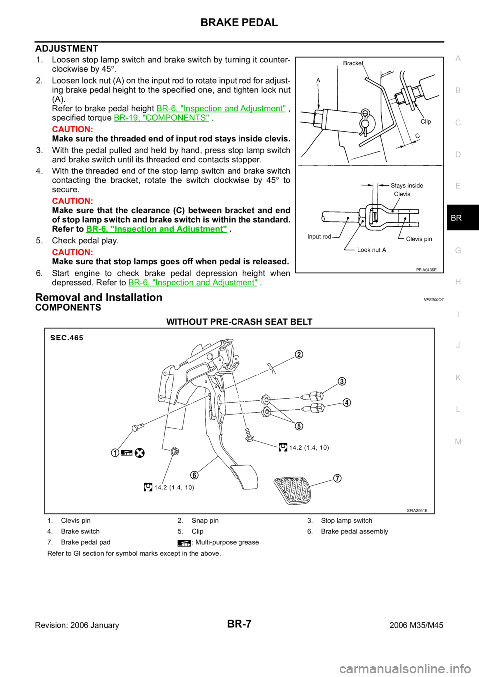
Before working, turn ignition switch OFF and disconnect con-
nectors of ABS actuator and electric unit (control unit) or battery
cable from the negative terminal.
Burnish the brake contact surfaces after refinishing or replacing
rotors, after replacing pads, or if a soft pedal occurs at very low
mileage. Refer to BR-28, "
BRAKE BURNISHING PROCE-
DURE" (front disc brake), BR-34, "BRAKE BURNISHING PRO-
CEDURE" (rear disc brake).
WAR NING :
Clean brake pads and shoes with a waste cloth, then wipe with a dust collector.
PIIB3706J
SBR686C
Page 1282 of 5621

BRAKE PEDAL
BR-7
C
D
E
G
H
I
J
K
L
MA
B
BR
Revision: 2006 January2006 M35/M45
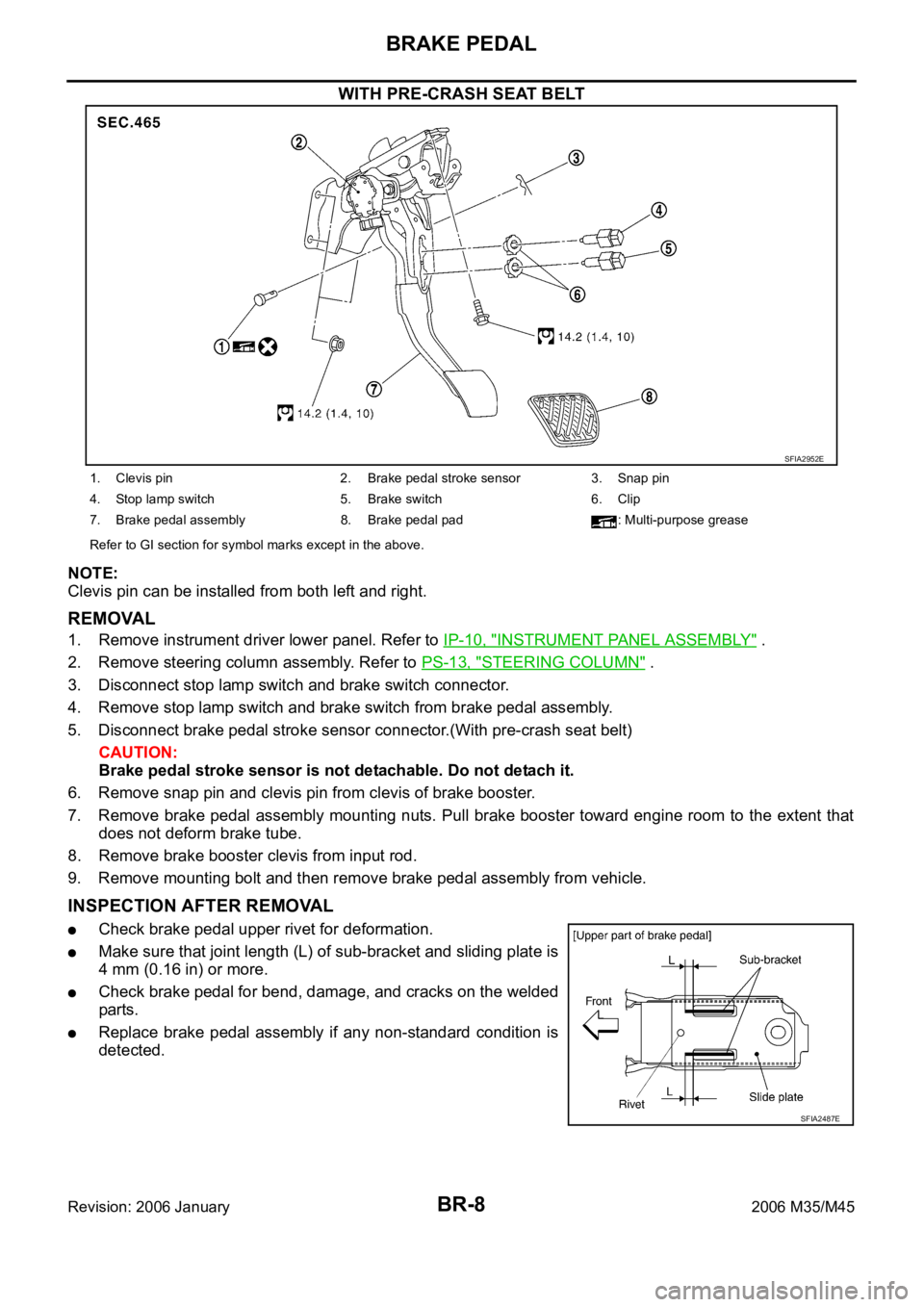
ADJUSTMENT
1. Loosen stop lamp switch and brake switch by turning it counter-
clockwise by 45
.
2. Loosen lock nut (A) on the input rod to rotate input rod for adjust-
ing brake pedal height to the specified one, and tighten lock nut
(A).
Refer to brake pedal height BR-6, "
Inspection and Adjustment" ,
specified torque BR-19, "
COMPONENTS" .
CAUTION:
Make sure the threaded end of input rod stays inside clevis.
3. With the pedal pulled and held by hand, press stop lamp switch
and brake switch until its threaded end contacts stopper.
4. With the threaded end of the stop lamp switch and brake switch
contacting the bracket, rotate the switch clockwise by 45
to
secure.
CAUTION:
Make sure that the clearance (C) between bracket and end
of stop lamp switch and brake switch is within the standard.
Refer to BR-6, "
Inspection and Adjustment" .
5. Check pedal play.
CAUTION:
Make sure that stop lamps goes off when pedal is released.
6. Start engine to check brake pedal depression height when
depressed. Refer to BR-6, "
Inspection and Adjustment" .
Removal and InstallationNFS000OT
COMPONENTS
WITHOUT PRE-CRASH SEAT BELT
PFIA0436E
SFIA2951E
1. Clevis pin 2. Snap pin 3. Stop lamp switch
4. Brake switch 5. Clip 6. Brake pedal assembly
7. Brake pedal pad : Multi-purpose grease
Refer to GI section for symbol marks except in the above.
Page 1283 of 5621

BR-8
BRAKE PEDAL
Revision: 2006 January2006 M35/M45
WITH PRE-CRASH SEAT BELT
NOTE:
Clevis pin can be installed from both left and right.
REMOVAL
1. Remove instrument driver lower panel. Refer to IP-10, "INSTRUMENT PANEL ASSEMBLY" .
2. Remove steering column assembly. Refer to PS-13, "
STEERING COLUMN" .
3. Disconnect stop lamp switch and brake switch connector.
4. Remove stop lamp switch and brake switch from brake pedal assembly.
5. Disconnect brake pedal stroke sensor connector.(With pre-crash seat belt)
CAUTION:
Brake pedal stroke sensor is not detachable. Do not detach it.
6. Remove snap pin and clevis pin from clevis of brake booster.
7. Remove brake pedal assembly mounting nuts. Pull brake booster toward engine room to the extent that
does not deform brake tube.
8. Remove brake booster clevis from input rod.
9. Remove mounting bolt and then remove brake pedal assembly from vehicle.
INSPECTION AFTER REMOVAL
Check brake pedal upper rivet for deformation.
Make sure that joint length (L) of sub-bracket and sliding plate is
4 mm (0.16 in) or more.
Check brake pedal for bend, damage, and cracks on the welded
parts.
Replace brake pedal assembly if any non-standard condition is
detected.
SFIA2952E
1. Clevis pin 2. Brake pedal stroke sensor 3. Snap pin
4. Stop lamp switch 5. Brake switch 6. Clip
7. Brake pedal assembly 8. Brake pedal pad : Multi-purpose grease
Refer to GI section for symbol marks except in the above.
SFIA2487E