2006 INFINITI M35 ESP
[x] Cancel search: ESPPage 1069 of 5621

BL-130
INTELLIGENT KEY SYSTEM/ENGINE START FUNCTION
Revision: 2006 January2006 M35/M45
starter motor relay. (If the engine initiating has failed, the cranking will stop automatically within 5 sec-
onds.)
CAUTION:
When the Intelligent Key is carried outside of the vehicle (inside key antenna detection area) with
the power supply in ACC or ON position, even if the engine start condition* is satisfied, the engine
cannot be started.
*: For the engine start condition, refer to BL-130, "
PUSH-BUTTON IGNITION SWITCH OPERATION PROCE-
DURE" .
Operation Range
Engine can be started when Intelligent Key is inside the vehicle. However, sometimes engine might not start
when Intelligent Key is on instrument panel or in glove box.
OPERATION WHEN KEY SLOT IS USED
When the Intelligent Key battery is discharged, it performs the immobilizer ID verification between the inte-
grated transponder and BCM by inserting the Intelligent Key into the key slot, and then the engine can be
started.
For details relating to starting the engine using key slot, refer to BL-248, "
IVIS (INFINITI VEHICLE IMMOBI-
LIZER SYSTEM-NATS)" .
PUSH-BUTTON IGNITION SWITCH OPERATION PROCEDURE
The power supply position changing operation can be performed with the following operation.
NOTE:
When an Intelligent Key is within the detection area of inside key antenna and when it is inserted to the
key slot, it is equivalent to the operations below.
When starting the engine, the Intelligent Key unit monitors the engine start conditions (brake pedal operat-
ing condition, A/T selector lever position, and vehicle speed).
Unless each start condition is fulfilled, the engine will not respond regardless of how many times the
engine switch is pushed. At that time, illumination repeats the position in the order of LOCK
AC-
C
ONLOCK.
Power supply positionEngine start/stop condition
Push-button ignition switch
operation frequency
Brake pedal A/T selector lever position
LOCK
ACCNot depressed
(When A/T selector lever is in any
position other than P or N, there
will be no effect even if it is
depressed.)Any position other than P or N
(When the brake pedal is not
depressed, there will be no effect
even if the A/T selector lever is in
P or N position.)1
LOCK
ACC ONNot depressed
(When A/T selector lever is in any
position other than P or N, there
will be no effect even if it is
depressed.)Any position other than P or N
(When the brake pedal is not
depressed, there will be no effect
even if the A/T selector lever is in
P or N position.)2
LOCK
ACC ON
LOCKNot depressed
(When A/T selector lever is in any
position other than P or N, there
will be no effect even if it is
depressed.)Any position other than P or N
(When the brake pedal is not
depressed, there will be no effect
even if the A/T selector lever is in
P or N position.)3
LOCK
START
ACC
START
ON
START
(Engine start)Depressed P or N position (*1)1
[If the switch is pushed once,
the engine starts from any
power supply position (LOCK,
ACC, and ON)]
Engine is running
LOCK
(Engine stop)— P position 1
Page 1089 of 5621

BL-150
INTELLIGENT KEY SYSTEM/ENGINE START FUNCTION
Revision: 2006 January2006 M35/M45
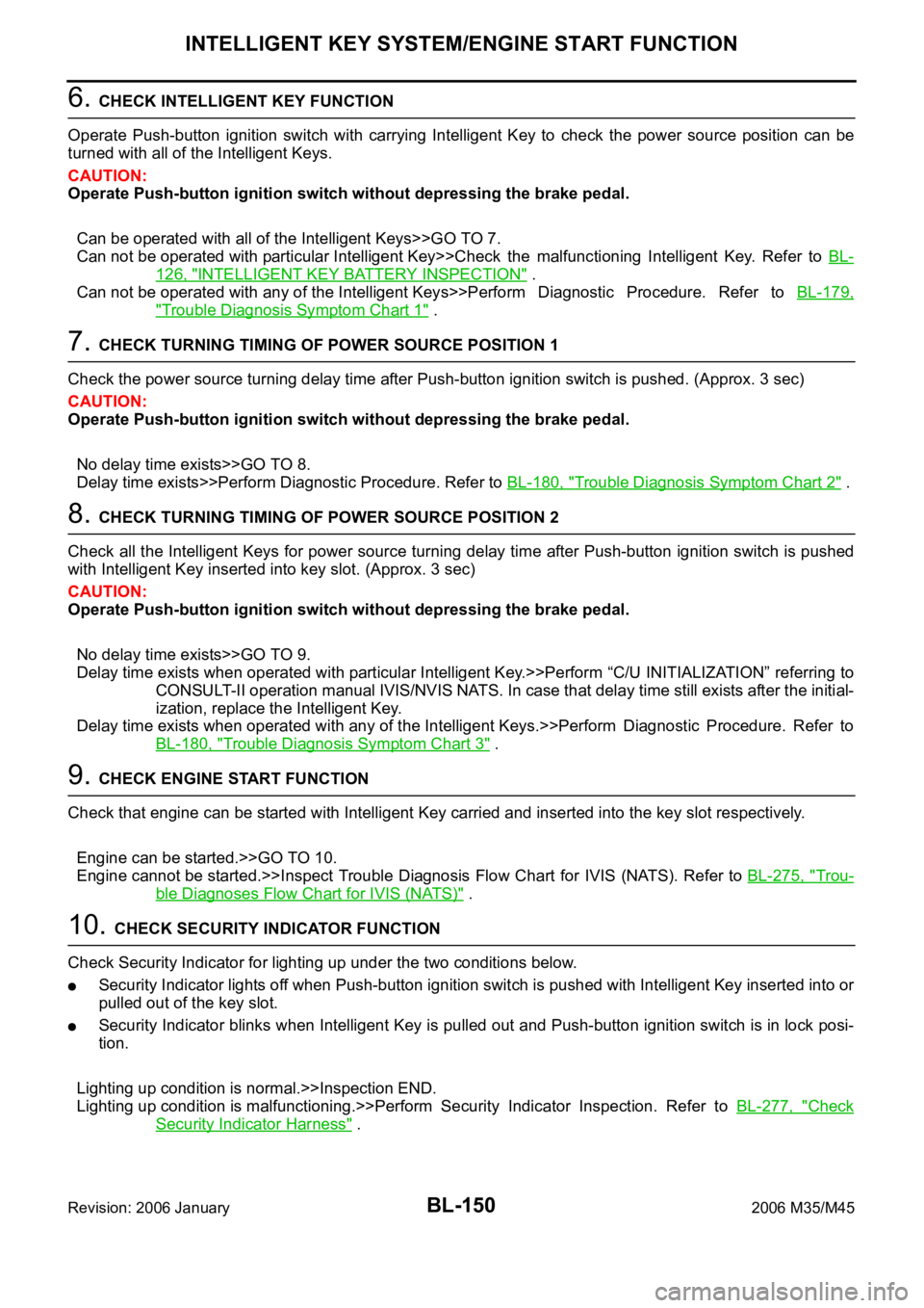
6. CHECK INTELLIGENT KEY FUNCTION
Operate Push-button ignition switch with carrying Intelligent Key to check the power source position can be
turned with all of the Intelligent Keys.
CAUTION:
Operate Push-button ignition switch without depressing the brake pedal.
Can be operated with all of the Intelligent Keys>>GO TO 7.
Can not be operated with particular Intelligent Key>>Check the malfunctioning Intelligent Key. Refer to BL-
126, "INTELLIGENT KEY BATTERY INSPECTION" .
Can not be operated with any of the Intelligent Keys>>Perform Diagnostic Procedure. Refer to BL-179,
"Trouble Diagnosis Symptom Chart 1" .
7. CHECK TURNING TIMING OF POWER SOURCE POSITION 1
Check the power source turning delay time after Push-button ignition switch is pushed. (Approx. 3 sec)
CAUTION:
Operate Push-button ignition switch without depressing the brake pedal.
No delay time exists>>GO TO 8.
Delay time exists>>Perform Diagnostic Procedure. Refer to BL-180, "
Trouble Diagnosis Symptom Chart 2" .
8. CHECK TURNING TIMING OF POWER SOURCE POSITION 2
Check all the Intelligent Keys for power source turning delay time after Push-button ignition switch is pushed
with Intelligent Key inserted into key slot. (Approx. 3 sec)
CAUTION:
Operate Push-button ignition switch without depressing the brake pedal.
No delay time exists>>GO TO 9.
Delay time exists when operated with particular Intelligent Key.>>Perform “C/U INITIALIZATION” referring to
CONSULT-II operation manual IVIS/NVIS NATS. In case that delay time still exists after the initial-
ization, replace the Intelligent Key.
Delay time exists when operated with any of the Intelligent Keys.>>Perform Diagnostic Procedure. Refer to
BL-180, "
Trouble Diagnosis Symptom Chart 3" .
9. CHECK ENGINE START FUNCTION
Check that engine can be started with Intelligent Key carried and inserted into the key slot respectively.
Engine can be started.>>GO TO 10.
Engine cannot be started.>>Inspect Trouble Diagnosis Flow Chart for IVIS (NATS). Refer to BL-275, "
Trou-
ble Diagnoses Flow Chart for IVIS (NATS)" .
10. CHECK SECURITY INDICATOR FUNCTION
Check Security Indicator for lighting up under the two conditions below.
Security Indicator lights off when Push-button ignition switch is pushed with Intelligent Key inserted into or
pulled out of the key slot.
Security Indicator blinks when Intelligent Key is pulled out and Push-button ignition switch is in lock posi-
tion.
Lighting up condition is normal.>>Inspection END.
Lighting up condition is malfunctioning.>>Perform Security Indicator Inspection. Refer to BL-277, "
Check
Security Indicator Harness" .
Page 1122 of 5621

INTELLIGENT KEY SYSTEM/ENGINE START FUNCTION
BL-183
C
D
E
F
G
H
J
K
L
MA
B
BL
Revision: 2006 January2006 M35/M45
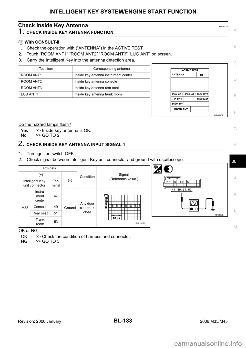
Check Inside Key AntennaNIS001Z5
1. CHECK INSIDE KEY ANTENNA FUNCTION
With CONSULT-II
1. Check the operation with (“ANTENNA”) in the ACTIVE TEST.
2. Touch “ROOM ANT1” “ROOM ANT2” “ROOM ANT3” “LUG ANT” on screen.
3. Carry the Intelligent Key into the antenna detection area.
Do the hazard lamps flash?
Yes >> Inside key antenna is OK.
No >> GO TO 2.
2. CHECK INSIDE KEY ANTENNA INPUT SIGNAL 1
1. Turn ignition switch OFF.
2. Check signal between Intelligent Key unit connector and ground with oscilloscope.
OK or NG
OK >> Check the condition of harness and connector.
NG >> GO TO 3.
Test item Corresponding antenna
ROOM ANT1 Inside key antenna instrument center
ROOM ANT2 Inside key antenna console
ROOM ANT3 Inside key antenna rear seat
LUG ANT1 Inside key antenna trunk room
PIIB6345E
Terminals
ConditionSignal
(Reference value.) (+)
(–)
Intelligent Key
unit connectorTe r -
minal
M33Instru-
ment
center47
GroundAny door
is open
close Console 49
Rear seat 51
Trunk
room53
PIIB6350E
SIIA1910J
Page 1191 of 5621

BL-252
IVIS (INFINITI VEHICLE IMMOBILIZER SYSTEM-NATS)
Revision: 2006 January2006 M35/M45
Unless each start condition is fulfilled, the engine will not response regardless of how many times the
push-button ignition switch is pushed. At that time, illumination repeats the position in the order of LOCK
ACC ON LOCK.
*1: When the A/T selector lever position is N position, the engine start condition is different according to the vehicle speed.
At vehicle speed of 5 km/h or less, the engine can start only when the brake pedal is depressed.
At vehicle speed of 5 km/h or more, the engine can start even if the brake pedal is not depressed. (It is the same as “Engine stall
return operation while driving”.)
*2: When the A/T selector lever position is in any position other than P position and when the vehicle speed is 5 km/h or more, the
engine stop condition is different.
Press and hold the push-button ignition switch for 2 seconds or more. (When the push-button ignition switch is pressed for too short
a time, the operation may be invalid, so properly press and hold to prevent the incorrect operation.)
Press the push-button ignition switch 3 times within 1.5 seconds. (Emergency stop operation)
ECM Re-Communicating FunctionNIS0020F
Performing following procedure can automatically perform re-communication of ECM and BCM or Intelligent
Key unit, but only when the ECM has been replaced with a new one (*1).
*1: New one means a virgin ECM which has never been energized on-board.
(In this step, initialization procedure by CONSULT-II is not necessary)
NOTE:
When registering new Key IDs or replacing the ECM other than brand new, refer to CONSULT-II
Operation Manual NATS-IVIS/NVIS.
If multiple keys are attached to the key holder, separate them before work.
Distinguish keys with unregistered key ID from those with registered ID.
1. Install ECM.
2. Insert the registered Intelligent Key (*2), turn ignition switch to “ON”.
*2: To perform this step, use the key that has been used before performing ECM replacement.
3. Maintain ignition switch in “ON” position for at least 5 seconds.
4. Turn ignition switch to “OFF”.
Power supply positionEngine start/stop condition
Engine switch operation fre-
quency
Brake pedal A/T selector lever position
LOCK
ACCNot depressed
(When A/T selector lever is in
any position other than P or N,
there will be no effect even if it
is depressed.)Any position other than P or N
(When the brake pedal is not
depressed, there will be no
effect even if the A/T selector
lever is in P or N position.)1
LOCK
ACC ONNot depressed
(When A/T selector lever is in
any position other than P or N,
there will be no effect even if it
is depressed.)Any position other than P or N
(When the brake pedal is not
depressed, there will be no
effect even if the A/T selector
lever is in P or N position.)2
LOCK
ACC ON LOCKNot depressed
(When A/T selector lever is in
any position other than P or N,
there will be no effect even if it
is depressed.)Any position other than P or N
(When the brake pedal is not
depressed, there will be no
effect even if the A/T selector
lever is in P or N position.)3
LOCK
START
ACC
START
ON
START
(Engine start)Depressed P or N position (*1)1
[If the switch is pushed once,
the engine starts from any
power supply position (LOCK,
ACC, and ON)]
Engine start condition
LOCK
(Engine stop)— P position 1
Engine start condition
ACC
(Engine stop)— Any position other than P (*2) 1
Engine stall return operation
while driving—N position 1
Page 1213 of 5621

BL-274
IVIS (INFINITI VEHICLE IMMOBILIZER SYSTEM-NATS)
Revision: 2006 January2006 M35/M45
8. CHECK TURNING TIMING OF POWER SOURCE POSITION 2
Check all the Intelligent Keys for power source turning delay time after Push-button ignition switch is pushed
with Intelligent Key inserted into key slot. (Approx. 3 sec)
CAUTION:
Operate Push-button ignition switch without depressing the brake pedal.
No delay time exists>>GO TO 9.
Delay time exists when operated with particular Intelligent Key.>>Perform “C/U INITIALIZATION” referring to
CONSULT-II operation manual IVIS/NVIS NATS. In case that delay time still exists after the initial-
ization, replace the Intelligent Key.
Delay time exists when operated with any of the Intelligent Keys.>>Perform Trouble diagnosis symptom
chart 3. Refer to BL-180, "
Trouble Diagnosis Symptom Chart 3" .
9. CHECK ENGINE START FUNCTION
Check that engine can be started with Intelligent Key carried and inserted into the key slot respectively.
Engine can be started.>>GO TO 10.
Engine cannot be started.>>Inspect Trouble Diagnosis Flow Chart for IVIS (NATS). Refer to BL-275, "
Trou-
ble Diagnoses Flow Chart for IVIS (NATS)" .
10. CHECK SECURITY INDICATOR FUNCTION
Check Security Indicator for lighting up under the two conditions below.
Security Indicator lights off when Push-button ignition switch is pushed with Intelligent Key inserted into or
pulled out of the key slot.
Security Indicator blinks when Intelligent Key is pulled out and Push-button ignition switch is in lock posi-
tion.
Lighting up condition is normal.>>Inspection END.
Lighting up condition is malfunctioning.>>Perform Security Indicator Inspection. Refer to BL-277, "
Symptom
Chart for Security Indicator" .
Page 1296 of 5621

VACUUM LINES
BR-21
C
D
E
G
H
I
J
K
L
MA
B
BR
Revision: 2006 January2006 M35/M45
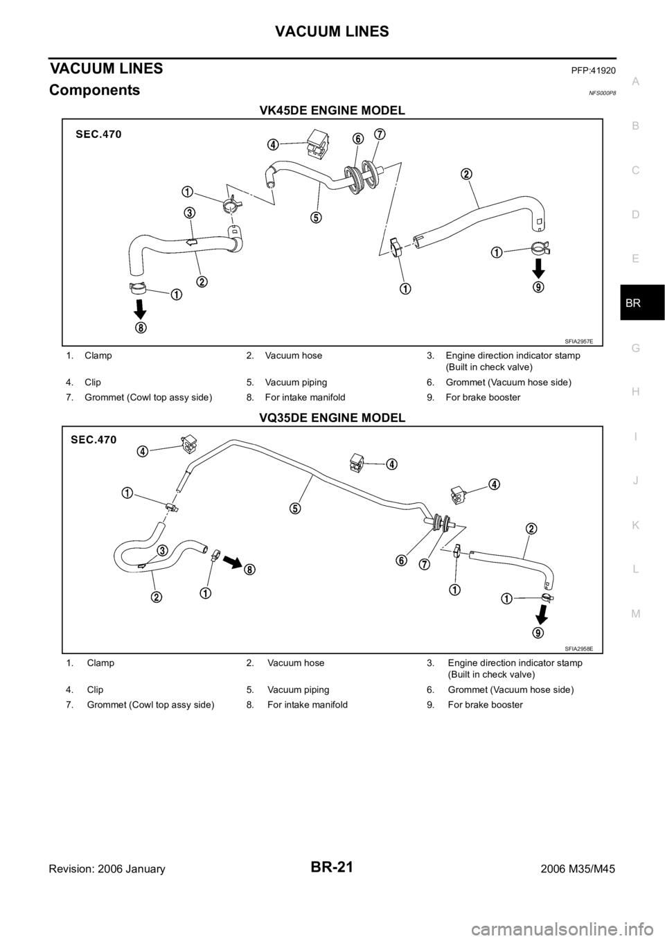
VACUUM LINESPFP:41920
ComponentsNFS000P8
VK45DE ENGINE MODEL
VQ35DE ENGINE MODEL
SFIA2957E
1. Clamp 2. Vacuum hose 3. Engine direction indicator stamp
(Built in check valve)
4. Clip 5. Vacuum piping 6. Grommet (Vacuum hose side)
7. Grommet (Cowl top assy side) 8. For intake manifold 9. For brake booster
SFIA2958E
1. Clamp 2. Vacuum hose 3. Engine direction indicator stamp
(Built in check valve)
4. Clip 5. Vacuum piping 6. Grommet (Vacuum hose side)
7. Grommet (Cowl top assy side) 8. For intake manifold 9. For brake booster
Page 1367 of 5621
![INFINITI M35 2006 Factory Service Manual BRC-56
[VDC/TCS/ABS]
TROUBLE DIAGNOSIS
Revision: 2006 January2006 M35/M45
Symptom 6 Vehicle Jerks During VDC/TCS/ABS ControlNFS000R9
1. SYMPTOM CHECK
Check if the vehicle jerks during VDC/TCS/ABS cont INFINITI M35 2006 Factory Service Manual BRC-56
[VDC/TCS/ABS]
TROUBLE DIAGNOSIS
Revision: 2006 January2006 M35/M45
Symptom 6 Vehicle Jerks During VDC/TCS/ABS ControlNFS000R9
1. SYMPTOM CHECK
Check if the vehicle jerks during VDC/TCS/ABS cont](/manual-img/42/57023/w960_57023-1366.png)
BRC-56
[VDC/TCS/ABS]
TROUBLE DIAGNOSIS
Revision: 2006 January2006 M35/M45
Symptom 6 Vehicle Jerks During VDC/TCS/ABS ControlNFS000R9
1. SYMPTOM CHECK
Check if the vehicle jerks during VDC/TCS/ABS control.
OK or NG
OK >> Normal.
NG >> GO TO 2.
2. CHECK SELF-DIAGNOSIS RESULTS
Perform self-diagnostic of ABS actuator and electric unit (control unit).
Are self-diagnosis results indicated?
YES >> Check corresponding items, make repairs, and perform ABS actuator and electric unit (control
unit) self-diagnosis.
NO >> GO TO 3.
3. CHECK CONNECTOR
Turn ignition switch OFF and disconnect ABS actuator and electric unit (control unit) connector and check
terminal for deformation, disconnection, looseness, etc.
Securely connect connectors and perform ABS actuator and electric unit (control unit) self-diagnosis.
Are self-diagnosis results indicated?
YES >> If poor contact, damage, open or short circuit of connector terminal is found, repair or replace.
NO >> GO TO 4.
4. CHECK ECM AND A/T SELF-DIAGNOSIS RESULTS
Perform ECM and A/T self-diagnosis.
Are self-diagnosis results indicated?
YES >> Check the corresponding items.
ECM: Refer to EC-100, "TROUBLE DIAGNOSIS" (VQ35DE), EC-811, "TROUBLE DIAGNO-
SIS" (VK45DE).
A/T: Refer to AT-44, "TROUBLE DIAGNOSIS" .
NO >> Replace ABS actuator and electric unit (control unit).
Page 1451 of 5621

DI-18
COMBINATION METERS
Revision: 2006 January2006 M35/M45
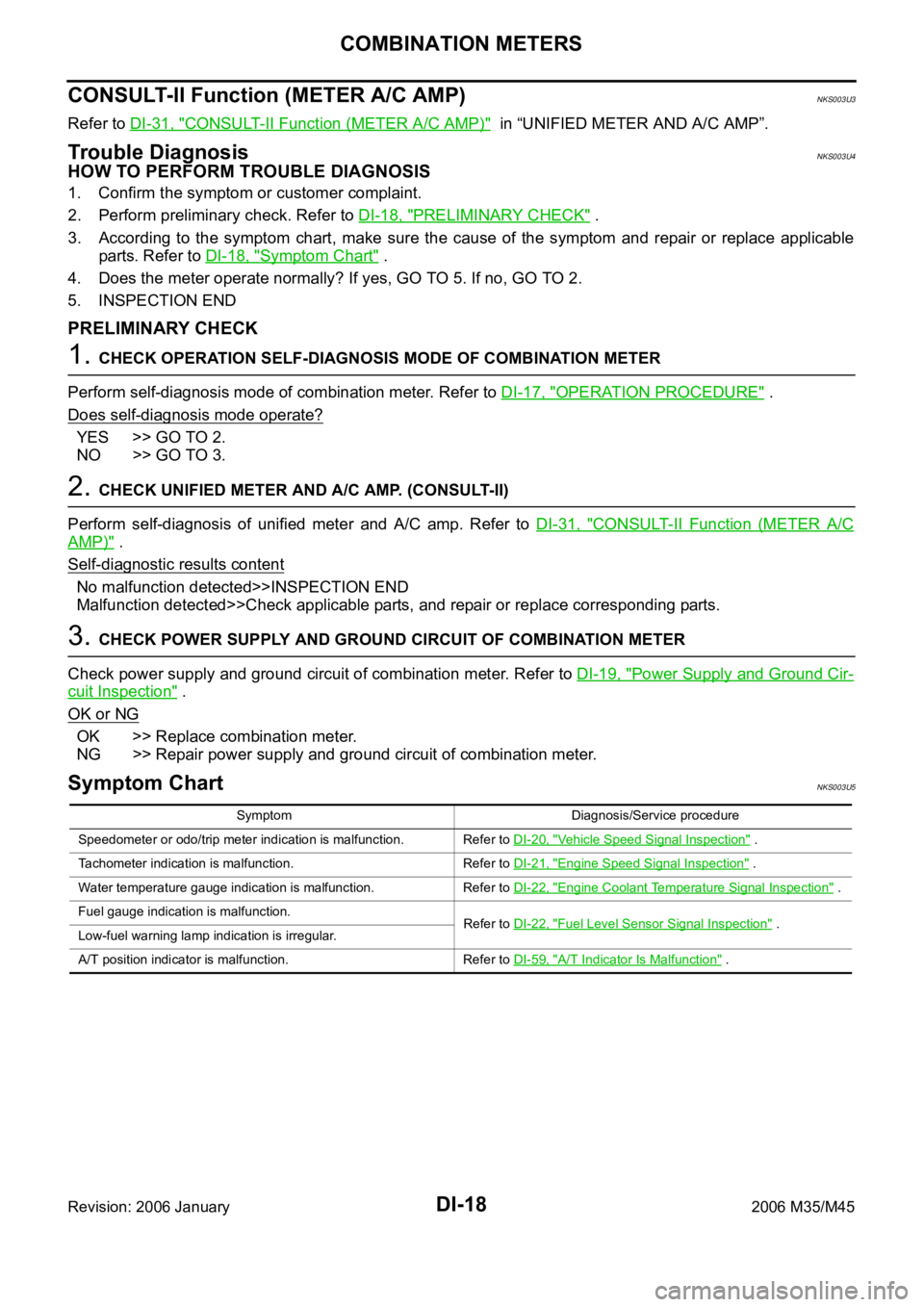
CONSULT-II Function (METER A/C AMP)NKS003U3
Refer to DI-31, "CONSULT-II Function (METER A/C AMP)" in “UNIFIED METER AND A/C AMP”.
Trouble DiagnosisNKS003U4
HOW TO PERFORM TROUBLE DIAGNOSIS
1. Confirm the symptom or customer complaint.
2. Perform preliminary check. Refer to DI-18, "
PRELIMINARY CHECK" .
3. According to the symptom chart, make sure the cause of the symptom and repair or replace applicable
parts. Refer to DI-18, "
Symptom Chart" .
4. Does the meter operate normally? If yes, GO TO 5. If no, GO TO 2.
5. INSPECTION END
PRELIMINARY CHECK
1. CHECK OPERATION SELF-DIAGNOSIS MODE OF COMBINATION METER
Perform self-diagnosis mode of combination meter. Refer to DI-17, "
OPERATION PROCEDURE" .
Does self
-diagnosis mode operate?
YES >> GO TO 2.
NO >> GO TO 3.
2. CHECK UNIFIED METER AND A/C AMP. (CONSULT-II)
Perform self-diagnosis of unified meter and A/C amp. Refer to DI-31, "
CONSULT-II Function (METER A/C
AMP)" .
Self
-diagnostic results content
No malfunction detected>>INSPECTION END
Malfunction detected>>Check applicable parts, and repair or replace corresponding parts.
3. CHECK POWER SUPPLY AND GROUND CIRCUIT OF COMBINATION METER
Check power supply and ground circuit of combination meter. Refer to DI-19, "
Power Supply and Ground Cir-
cuit Inspection" .
OK or NG
OK >> Replace combination meter.
NG >> Repair power supply and ground circuit of combination meter.
Symptom ChartNKS003U5
Symptom Diagnosis/Service procedure
Speedometer or odo/trip meter indication is malfunction. Refer to DI-20, "
Vehicle Speed Signal Inspection" .
Tachometer indication is malfunction. Refer to DI-21, "
Engine Speed Signal Inspection" .
Water temperature gauge indication is malfunction. Refer to DI-22, "
Engine Coolant Temperature Signal Inspection" .
Fuel gauge indication is malfunction.
Refer to DI-22, "
Fuel Level Sensor Signal Inspection" .
Low-fuel warning lamp indication is irregular.
A/T position indicator is malfunction. Refer to DI-59, "
A/T Indicator Is Malfunction" .