2006 INFINITI M35 turn signal
[x] Cancel search: turn signalPage 3313 of 5621
![INFINITI M35 2006 Factory Service Manual EM-250
[VK45DE]
CYLINDER BLOCK
Revision: 2006 January2006 M35/M45
Disassembly and AssemblyNBS004PN
DISASSEMBLY
NOTE:
Explained here is how to disassemble with engine stand supporting transmission su INFINITI M35 2006 Factory Service Manual EM-250
[VK45DE]
CYLINDER BLOCK
Revision: 2006 January2006 M35/M45
Disassembly and AssemblyNBS004PN
DISASSEMBLY
NOTE:
Explained here is how to disassemble with engine stand supporting transmission su](/manual-img/42/57023/w960_57023-3312.png)
EM-250
[VK45DE]
CYLINDER BLOCK
Revision: 2006 January2006 M35/M45
Disassembly and AssemblyNBS004PN
DISASSEMBLY
NOTE:
Explained here is how to disassemble with engine stand supporting transmission surface. When using differ-
ent type of engine stand, note with difference in steps and etc.
1. Remove engine assembly from vehicle, and separate front suspension member, transmission from
engine. Refer to EM-244, "
ENGINE ASSEMBLY" .
2. Remove the parts that may restrict installation of engine to widely use engine stand.
NOTE:
The procedure is described assuming that you use widely use engine holding the surface, to which trans-
mission is installed.
a. Remove drive plate.
Holding ring gear with ring gear stopper (SST).
Loosen mounting bolts diagonally order.
CAUTION:
Do not disassemble drive plate.
Do not place drive plate with signal plate facing down.
When handling signal plate, take care not to damage or
scratch it.
Handle signal plate in a manner that prevents it from
becoming magnetized.
b. Remove rear plate.
3. Lift engine with hoist to install it onto widely use engine stand.
CAUTION:
Use engine stand that has a load capacity [approximately 240kg (529 lb) or more] large enough for
supporting the engine weight.
If the load capacity of stand is not adequate, remove the following parts beforehand to reduce the
potential risk of overturning stand.
–Intake manifolds (upper and lower); Refer to EM-179, "INTAKE MANIFOLD" .
–Exhaust manifold and three way catalyst; Refer to EM-183, "EXHAUST MANIFOLD AND THREE WAY
CATALYST" .
13. Piston pin 14. Connecting rod bearing 15. Connecting rod bearing cap
16. Block heater protector 17. Connector cap 18. Cylinder block heater
19. Gasket 20. Main bearing cap 21. Thrust bearing
22. Main bearing 23. Rear plate 24. Crankshaft
25. Pilot convertor 26. Drive plate 27. Thrust bearing
28. Side bolt 29. Reinforcement plate 30. Crankshaft position sensor (POS)
31. O-ring 32. Rear oil seal 33. Rear oil seal retainer
PBIC1656E
PBIC2367E
Page 3535 of 5621

GW-16
POWER WINDOW SYSTEM
Revision: 2006 January2006 M35/M45
AUTO OPERATION
The power window AUTO feature enables the driver to open or close the window without holding the window
switch in the down or up position.
POWER WINDOW SERIAL LINK
Power window main switch, any power window sub-switches and BCM transmit and receive the signal by
power window serial link.
The under mentioned signal is transmitted from BCM to power window main switch and power window sub-
switches.
Keyless power window down signal.
The under mentioned signal is transmitted from power window main switch to power window sub-switch (front
passenger side)
Front passenger side door window operation signal.
Power window control by key cylinder switch signal.
Power window lock signal.
Retained power operation signal.
The under mentioned signal is transmitted from power window main switch to power window sub-switch (rear
LH or RH)
Rear LH or RH side door window operation signal.
Power window control by key cylinder switch signal.
Power window lock signal.
Retained power operation signal.
POWER WINDOW LOCK
The power window lock is designed to lock operation of all windows except for driver side door window.
When the lock position, the power window lock signal is transmitted to any power window sub-switches by
power window serial link. This prevents the power window motors from operating.
RETAINED POWER OPERATION
When the ignition switch is turned to the OFF position from ON or START position.
Power is supplied for 45 seconds
through BCM terminal 53
to power window main switch terminal 10.
When power and ground are supplied, the BCM continues to be energized, and the power window can be
operated.
The retained power operation is canceled when the driver or passenger side door is opened.
RAP signal period can be changed by CONSULT-II. Refer to GW-30, "
CONSULT-II Function (BCM)" .
Page 3537 of 5621

GW-18
POWER WINDOW SYSTEM
Revision: 2006 January2006 M35/M45
FAIL-SAFE CONTROL
The encoder signal detects the up / down speed / detection of door glass. If the malfunction is detected to the
encoder signal or the difference between the glass fully closed position (memorized in power window main
switch or power window sub-switch) and the actual glass position is detected, it shifts into the fail-safe control
It is shifts into the fail-safe control, the initialization is not performed and the following function is not activated
Auto up operation
Anti-pinch function
It is shifts into the fail-safe control, performed the initialization to resume normal operation condition.
POWER WINDOW CONTROL BY THE KEY CYLINDER SWITCH
When ignition key switch is OFF, front power window can be opened or closed by turning the key cylinder
switch UNLOCK / LOCK position more than 1.5 second over condition.
Power window can be opened as the door key cylinder is kept fully turning to the UNLOCK position.
Power window can be closed as the door key cylinder is kept fully turning to the LOCK position.
The power window DOWN stops when the following operations are carried out.
While performing open / close the window, power window is stopped at the position as the door key cylin-
der is placed on NEUTRAL.
When the ignition switch is turned ON while the power window DOWN is operated.
DTC Condition
Pulse sensor detects malfunctionDuring the glass opening/closing operation, a pulse signal is continuously
detected for the specified terms or more
Both pulse sensors detect malfunctionDuring the glass opening/closing operation, both pulse signals are not
detected for the specified values or more
Pulse direction malfunctionThe following condition is detected for the specified values or more. The
pulse signal (detected during glass open/close operation) detects the
opposite direction to the driving direction of power window motor.
Glass recognized position malfunction 1During the glass opening/closing operation, the difference between the
glass fully closed position (memorized in power window main switch or
power window sub-switch) and the actual glass position is detected for
the specified values or more.
Glass recognized position malfunction 2During the glass opening/closing operation, a pulse count is detected that
is above the glass full stroke
Glass fully closed position not updated malfunctionContinuously perform the glass open/close operation (with the glass not
fully closed) at the specified value (approx. 10 time) or more
Page 3546 of 5621
![INFINITI M35 2006 Factory Service Manual POWER WINDOW SYSTEM
GW-27
C
D
E
F
G
H
J
K
L
MA
B
GW
Revision: 2006 January2006 M35/M45
Terminal and Reference Value for BCMNIS0021L
Terminal Wire color Item ConditionVoltage [V]
(Approx.)
12 PFront do INFINITI M35 2006 Factory Service Manual POWER WINDOW SYSTEM
GW-27
C
D
E
F
G
H
J
K
L
MA
B
GW
Revision: 2006 January2006 M35/M45
Terminal and Reference Value for BCMNIS0021L
Terminal Wire color Item ConditionVoltage [V]
(Approx.)
12 PFront do](/manual-img/42/57023/w960_57023-3545.png)
POWER WINDOW SYSTEM
GW-27
C
D
E
F
G
H
J
K
L
MA
B
GW
Revision: 2006 January2006 M35/M45
Terminal and Reference Value for BCMNIS0021L
Terminal Wire color Item ConditionVoltage [V]
(Approx.)
12 PFront door switch
passenger side signalON (Open) 0
OFF (Close) Battery voltage
22 G Power window serial link IGN SW ON or power window
timer operating.
38 W Ignition switch (ON or START) Ignition switch
(ON or START position)Battery voltage
39 L CAN - H — —
40 P CAN - L — —
42 P Power source (Fuse) — Battery voltage
52 B Ground — 0
53 BR Rap signalIGN SW ON Battery voltage
Within 45 second after ignition
switch is turned to OFFBattery voltage
When driver side or passenger
side door is opened daring
retained power operation0
54 O Power window power supply — Battery voltage
55 W Power source (Fusible link) — Battery voltage
62 VFront door switch
driver side signalON (Open) 0
OFF (Close) Battery voltage
PIIA2344J
Page 3547 of 5621
![INFINITI M35 2006 Factory Service Manual GW-28
POWER WINDOW SYSTEM
Revision: 2006 January2006 M35/M45
Terminal and Reference Value for Power Window Main SwitchNIS0021M
Terminal Wire color Item ConditionVoltage [V]
(Approx.)
2 W/B Encoder gro INFINITI M35 2006 Factory Service Manual GW-28
POWER WINDOW SYSTEM
Revision: 2006 January2006 M35/M45
Terminal and Reference Value for Power Window Main SwitchNIS0021M
Terminal Wire color Item ConditionVoltage [V]
(Approx.)
2 W/B Encoder gro](/manual-img/42/57023/w960_57023-3546.png)
GW-28
POWER WINDOW SYSTEM
Revision: 2006 January2006 M35/M45
Terminal and Reference Value for Power Window Main SwitchNIS0021M
Terminal Wire color Item ConditionVoltage [V]
(Approx.)
2 W/B Encoder ground — 0
4BRDoor key cylinder switch
LOCK signalKey position
(Neutral
Locked)5 0
6V/RDoor key cylinder switch
UNLOCK signalKey position
(Neutral
Unlocked)5 0
8LFront driver side power window
motor UP signalWhen front LH switch in
power window main switch is
UP at operated. Battery voltage
9 G/W Encoder pulse signal 2When power window motor oper-
ates.
10 Y/B Rap signalIGN SW ON Battery voltage
Within 45 second after ignition
switch is turned to OFFBattery voltage
When driver side or passenger
side door is opened daring
retained power operation0
11 GFront driver side power window
motor DOWN signalWhen front LH switch in
power window main switch is
DOWN at operated. Battery voltage
13 G/Y Encoder pulse signal 1When power window motor oper-
ates.
14 Y Power window serial linkIGN SW ON or power window
timer operating.
15 G/R Encoder power supplyWhen ignition switch ON or power
window timer operates.10
17 B Ground — 0
19 W/B Battery power supply — Battery voltage
OCC3383D
OCC3383D
PIIA2344J
Page 3555 of 5621

GW-36
POWER WINDOW SYSTEM
Revision: 2006 January2006 M35/M45
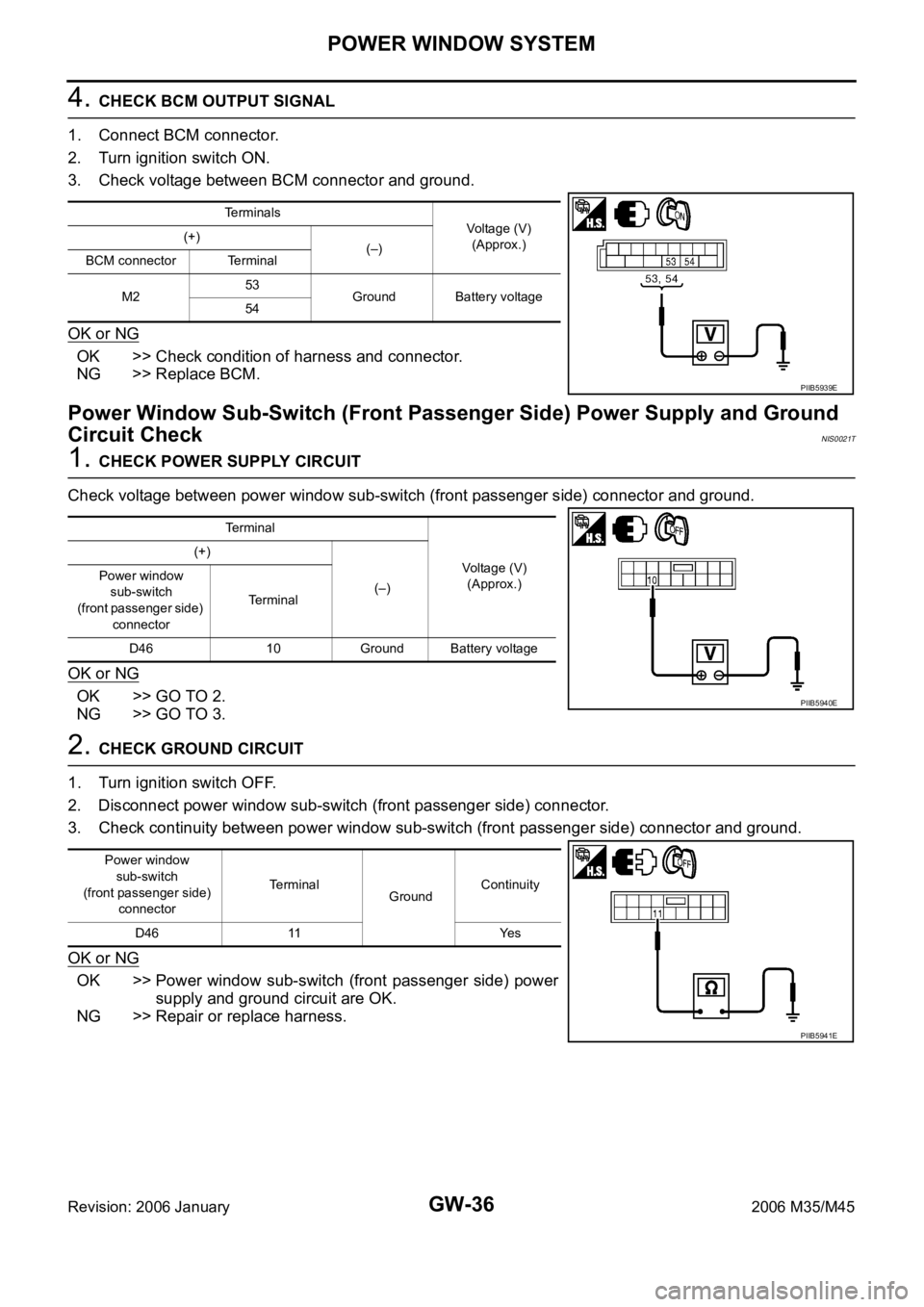
4. CHECK BCM OUTPUT SIGNAL
1. Connect BCM connector.
2. Turn ignition switch ON.
3. Check voltage between BCM connector and ground.
OK or NG
OK >> Check condition of harness and connector.
NG >> Replace BCM.
Power Window Sub-Switch (Front Passenger Side) Power Supply and Ground
Circuit Check
NIS0021T
1. CHECK POWER SUPPLY CIRCUIT
Check voltage between power window sub-switch (front passenger side) connector and ground.
OK or NG
OK >> GO TO 2.
NG >> GO TO 3.
2. CHECK GROUND CIRCUIT
1. Turn ignition switch OFF.
2. Disconnect power window sub-switch (front passenger side) connector.
3. Check continuity between power window sub-switch (front passenger side) connector and ground.
OK or NG
OK >> Power window sub-switch (front passenger side) power
supply and ground circuit are OK.
NG >> Repair or replace harness.
Terminals
Voltage (V)
(Approx.) (+)
(–)
BCM connector Terminal
M253
Ground Battery voltage
54
PIIB5939E
Terminal
Voltage (V)
(Approx.) (+)
(–) Power window
sub-switch
(front passenger side)
connectorTerminal
D46 10 Ground Battery voltage
PIIB5940E
Power window
sub-switch
(front passenger side)
connectorTerminal
GroundContinuity
D46 11 Yes
PIIB5941E
Page 3557 of 5621

GW-38
POWER WINDOW SYSTEM
Revision: 2006 January2006 M35/M45
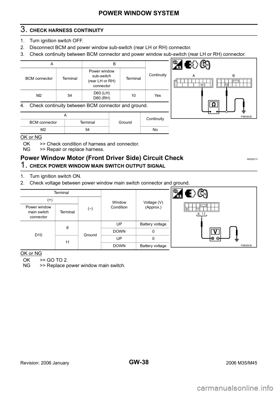
3. CHECK HARNESS CONTINUITY
1. Turn ignition switch OFF.
2. Disconnect BCM and power window sub-switch (rear LH or RH) connector.
3. Check continuity between BCM connector and power window sub-switch (rear LH or RH) connector.
4. Check continuity between BCM connector and ground.
OK or NG
OK >> Check condition of harness and connector.
NG >> Repair or replace harness.
Power Window Motor (Front Driver Side) Circuit CheckNIS0021V
1. CHECK POWER WINDOW MAIN SWITCH OUTPUT SIGNAL
1. Turn ignition switch ON.
2. Check voltage between power window main switch connector and ground.
OK or NG
OK >> GO TO 2.
NG >> Replace power window main switch.
AB
Continuity
BCM connector TerminalPower window
sub-switch
(rear LH or RH)
connectorTerminal
M2 54D60 (LH)
D80 (RH)10 Yes
A
GroundContinuity
BCM connector Terminal
M2 54 No
PIIB5942E
Terminal
Window
ConditionVoltage (V)
(Approx.) (+)
(–) Power window
main switch
connectorTerminal
D108
GroundUP Battery voltage
DOWN 0
11UP 0
DOWN Battery voltage
PIIB5943E
Page 3558 of 5621

POWER WINDOW SYSTEM
GW-39
C
D
E
F
G
H
J
K
L
MA
B
GW
Revision: 2006 January2006 M35/M45
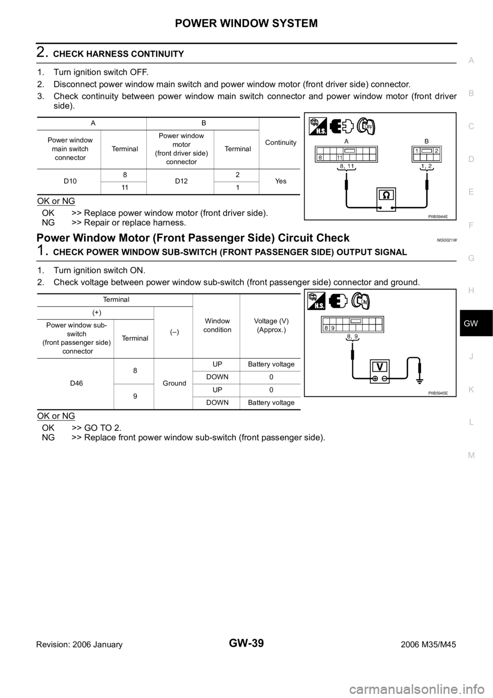
2. CHECK HARNESS CONTINUITY
1. Turn ignition switch OFF.
2. Disconnect power window main switch and power window motor (front driver side) connector.
3. Check continuity between power window main switch connector and power window motor (front driver
side).
OK or NG
OK >> Replace power window motor (front driver side).
NG >> Repair or replace harness.
Power Window Motor (Front Passenger Side) Circuit CheckNIS0021W
1. CHECK POWER WINDOW SUB-SWITCH (FRONT PASSENGER SIDE) OUTPUT SIGNAL
1. Turn ignition switch ON.
2. Check voltage between power window sub-switch (front passenger side) connector and ground.
OK or NG
OK >> GO TO 2.
NG >> Replace front power window sub-switch (front passenger side).
AB
Continuity Power window
main switch
connectorTerminalPower window
motor
(front driver side)
connectorTerminal
D108
D122
Ye s
11 1
PIIB5944E
Terminal
Window
conditionVoltage (V)
(Approx.) (+)
(–) Power window sub-
switch
(front passenger side)
connectorTerminal
D468
GroundUP Battery voltage
DOWN 0
9UP 0
DOWN Battery voltage
PIIB5945E