Page 4996 of 5621
HYDRAULIC LINE
PS-43
C
D
E
F
H
I
J
K
L
MA
B
PS
Revision: 2006 January2006 M35/M45
Removal and InstallationNGS000DL
Insert hose securely until it contacts tube spool.
CAUTION:
Do not apply fluid.
Install eye-bolt with eye-joint (assembled to high-pressure hose)
protrusion facing with pump side cutout, and then tighten it to
the specified torque after tightening by hand.
Refer to GI-11, "Components" , and the followings for the symbols in the figure.
: Apply power steering fluid.
SGIA0514E
SGIA0515E
Page 4997 of 5621

PS-44
SERVICE DATA AND SPECIFICATIONS (SDS)
Revision: 2006 January2006 M35/M45
SERVICE DATA AND SPECIFICATIONS (SDS)PFP:00030
Steering WheelNGS000DM
Steering AngleNGS000DN
Steering ColumnNGS000DO
Steering Outer Socket and Inner SocketNGS000DP
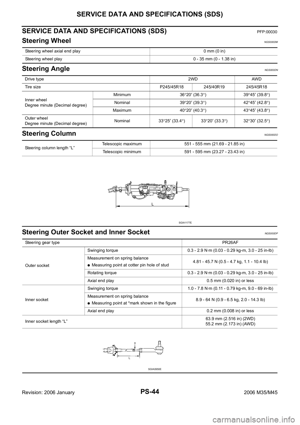
Steering wheel axial end play 0 mm (0 in)
Steering wheel play 0 - 35 mm (0 - 1.38 in)
Drive type2WD AWD
Tire size P245/45R18 245/40R19 245/45R18
Inner wheel
Degree minute (Decimal degree)Minimum 36
20 (36.3)3945 (39.8)
Nominal 39
20 (39.3)4245 (42.8)
Maximum 40
20 (40.3)4345 (43.8)
Outer wheel
Degree minute (Decimal degree)Nominal 33
25 (33.4)3320 (33.3)3230 (32.5)
Steering column length “L”Telescopic maximum 551 - 555 mm (21.69 - 21.85 in)
Telescopic minimum 591 - 595 mm (23.27 - 23.43 in)
SGIA1177E
Steering gear typePR26AF
Outer socketSwinging torque 0.3 - 2.9 Nꞏm (0.03 - 0.29 kg-m, 3.0 - 25 in-lb)
Measurement on spring balance
Measuring point at cotter pin hole of stud4.81 - 45.7 N (0.5 - 4.7 kg, 1.1 - 10.4 lb)
Rotating torque 0.3 - 2.9 Nꞏm (0.03 - 0.29 kg-m, 3.0 - 25 in-lb)
Axial end play 0.5 mm (0.020 in) or less
Inner socketSwinging torque 1.0 - 7.8 Nꞏm (0.11 - 0.79 kg-m, 9.0 - 69 in-lb)
Measurement on spring balance
Measuring point at *mark shown in the figure8.9 - 64 N (0.9 - 6.5 kg, 2.0 - 14.3 lb)
Axial end play 0.2 mm (0.008 in) or less
Inner socket length “L”63.9 mm (2.516 in) (2WD)
55.2 mm (2.173 in) (AWD)
SGIA0950E
Page 4998 of 5621
SERVICE DATA AND SPECIFICATIONS (SDS)
PS-45
C
D
E
F
H
I
J
K
L
MA
B
PS
Revision: 2006 January2006 M35/M45
Steering GearNGS000DQ
Oil PumpNGS000DR
Steering FluidNGS000DS
Steering gear model PR26AF
Drive type 2WD AWD
Rack neutral position, dimension “L” (rack stroke) 68.5 mm (2.697 in) 67.0 mm (2.638 in)
SGIA0877E
Oil pump relief hydraulic pressure
8,520 - 9,320 kPa (86.9 - 95.1 kg/cm2 , 1,235 - 1,351 psi)
Fluid capacity
Approx. 1.0 (1-1/8 US qt, 7/8 Imp qt)
Page 5003 of 5621
RAX-4
NOISE, VIBRATION AND HARSHNESS (NVH) TROUBLESHOOTING
Revision: 2006 January2006 M35/M45
NOISE, VIBRATION AND HARSHNESS (NVH) TROUBLESHOOTINGPFP:00003
NVH Troubleshooting ChartNDS000FP
Use chart below to help you find the cause of the symptom. If necessary, repair or replace these parts.
: ApplicableReference page
—
RAX-10—
RAX-8—
NVH in PR section.
NVH in RFD section.
NVH in RAX and RSU sections.
Refer to REAR AXLE in this chart.
NVH in WT section.
NVH in WT section.
Refer to DRIVE SHAFT in this chart.
NVH in BR section.
NVH in PS section.
Possible cause and SUSPECTED PARTS
Excessive joint angle
Joint sliding resistance
Imbalance
Improper installation, looseness
Parts interference
PROPELLER SHAFT
DIFFERENTIAL
REAR AXLE AND REAR SUSPENSION
REAR AXLE
TIRES
ROAD WHEEL
DRIVE SHAFT
BRAKES
STEERING
SymptomDRIVE
SHAFTNoise
Shake
REAR
AXLENoise
Shake
Vibration
Shimmy
Judder
Poor quality ride or handling
Page 5006 of 5621

WHEEL HUB
RAX-7
C
E
F
G
H
I
J
K
L
MA
B
RAX
Revision: 2006 January2006 M35/M45
INSTALLATION
Wheel Hub and Bearing Assembly
Installation is the reverse order of removal. For tightening torque refer to RAX-5, "COMPONENT" .
CAUTION:
Do not reuse non-reusable parts.
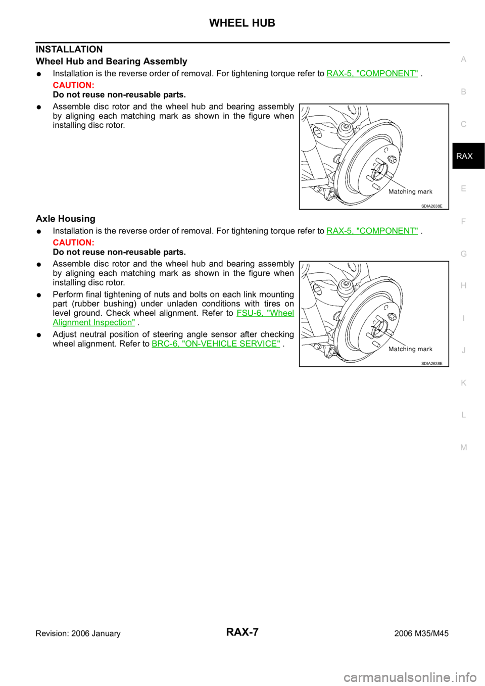
Assemble disc rotor and the wheel hub and bearing assembly
by aligning each matching mark as shown in the figure when
installing disc rotor.
Axle Housing
Installation is the reverse order of removal. For tightening torque refer to RAX-5, "COMPONENT" .
CAUTION:
Do not reuse non-reusable parts.
Assemble disc rotor and the wheel hub and bearing assembly
by aligning each matching mark as shown in the figure when
installing disc rotor.
Perform final tightening of nuts and bolts on each link mounting
part (rubber bushing) under unladen conditions with tires on
level ground. Check wheel alignment. Refer to FSU-6, "
Wheel
Alignment Inspection" .
Adjust neutral position of steering angle sensor after checking
wheel alignment. Refer to BRC-6, "
ON-VEHICLE SERVICE" .
SDIA2638E
SDIA2638E
Page 5050 of 5621

NOISE, VIBRATION AND HARSHNESS (NVH) TROUBLESHOOTING
RFD-7
C
E
F
G
H
I
J
K
L
MA
B
RFD
Revision: 2006 January2006 M35/M45
NOISE, VIBRATION AND HARSHNESS (NVH) TROUBLESHOOTINGPFP:00003
NVH Troubleshooting ChartNDS000F1
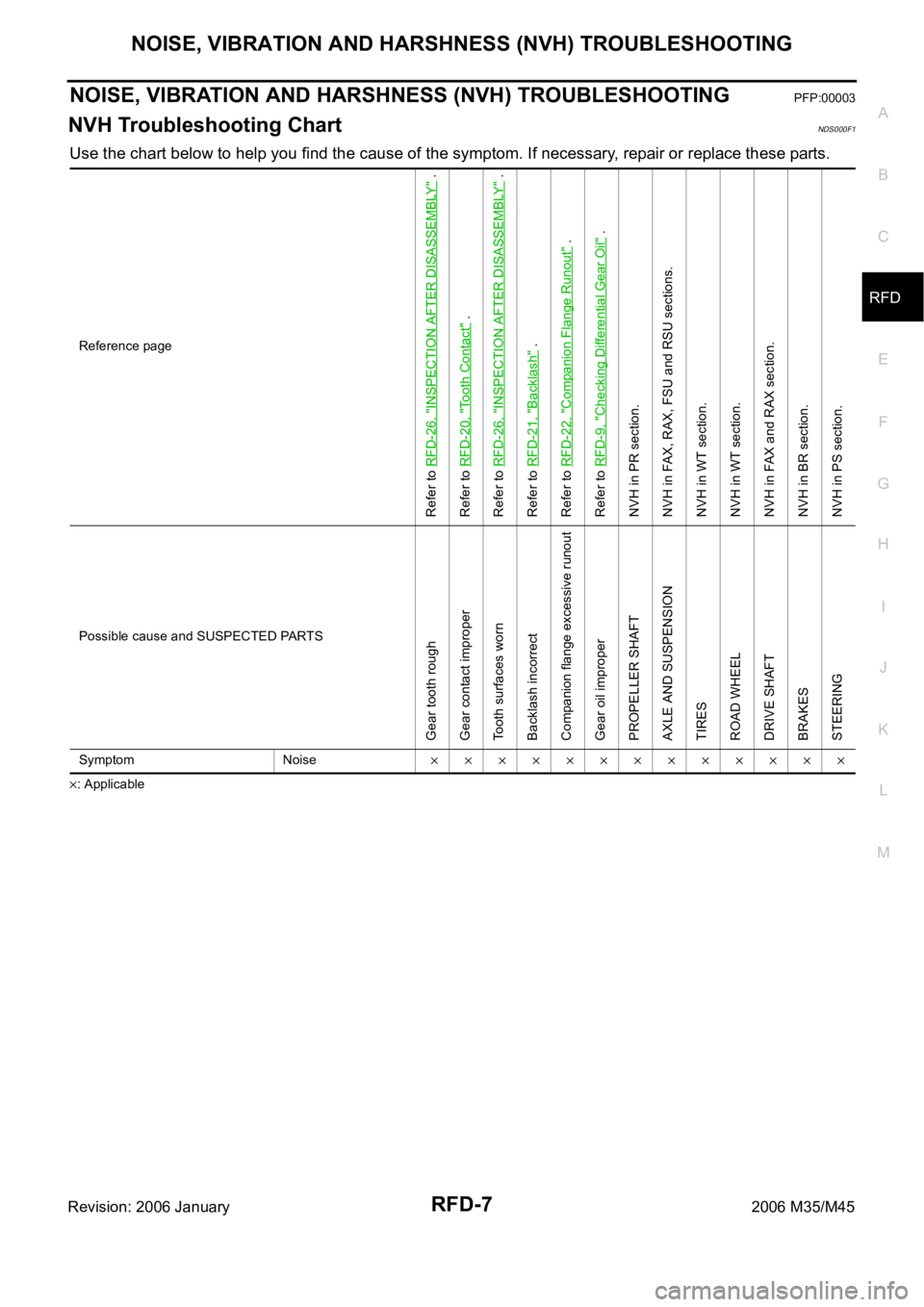
Use the chart below to help you find the cause of the symptom. If necessary, repair or replace these parts.
: ApplicableReference page
Refer to RFD-26, "
INSPECTION AFTER DISASSEMBLY
" .
Refer to RFD-20, "
Tooth Contact
" .
Refer to RFD-26, "
INSPECTION AFTER DISASSEMBLY
" .
Refer to RFD-21, "
Backlash
" .
Refer to RFD-22, "
Companion Flange Runout
" .
Refer to RFD-9, "
Checking Differential Gear Oil
" .
NVH in PR section.
NVH in FAX, RAX, FSU and RSU sections.
NVH in WT section.
NVH in WT section.
NVH in FAX and RAX section.
NVH in BR section.
NVH in PS section.
Possible cause and SUSPECTED PARTS
Gear tooth rough
Gear contact improper
Tooth surfaces worn
Backlash incorrect
Companion flange excessive runout
Gear oil improper
PROPELLER SHAFT
AXLE AND SUSPENSION
TIRES
ROAD WHEEL
DRIVE SHAFT
BRAKES
STEERING
Symptom Noise
Page 5085 of 5621
RSU-4
NOISE, VIBRATION AND HARSHNESS (NVH) TROUBLESHOOTING
Revision: 2006 January2006 M35/M45
NOISE, VIBRATION AND HARSHNESS (NVH) TROUBLESHOOTINGPFP:00003
NVH Troubleshooting ChartNES000J5
Use chart below to help you find the cause of the symptom. If necessary, repair or replace these parts.
: ApplicableReference page
RSU-7RSU-10
—
—
—
RSU-7RSU-5RSU-17
NVH in PR section.
NVH in RFD section.
NVH in RAX and RSU sections.
NVH in WT section.
NVH in WT section.
NVH in RAX section.
NVH in BR section.
NVH in PS section.
Possible cause and SUSPECTED PARTS
Improper installation, looseness
Shock absorber deformation, damage or deflection
Bushing or mounting deterioration
Parts interference
Spring fatigue
Suspension looseness
Incorrect wheel alignment
Stabilizer bar fatigue
PROPELLER SHAFT
DIFFERENTIAL
REAR AXLE AND REAR SUSPENSION
TIRES
ROAD WHEELS
DRIVE SHAFT
BRAKES
STEERING
Symptom REAR SUSPENSIONNoise
Shake
Vibration
Shimmy
Judder
Poor quality ride or
handling
Page 5086 of 5621

REAR SUSPENSION ASSEMBLY
RSU-5
C
D
F
G
H
I
J
K
L
MA
B
RSU
Revision: 2006 January2006 M35/M45
REAR SUSPENSION ASSEMBLYPFP:55020
On-Vehicle Inspection and ServiceNES000J6
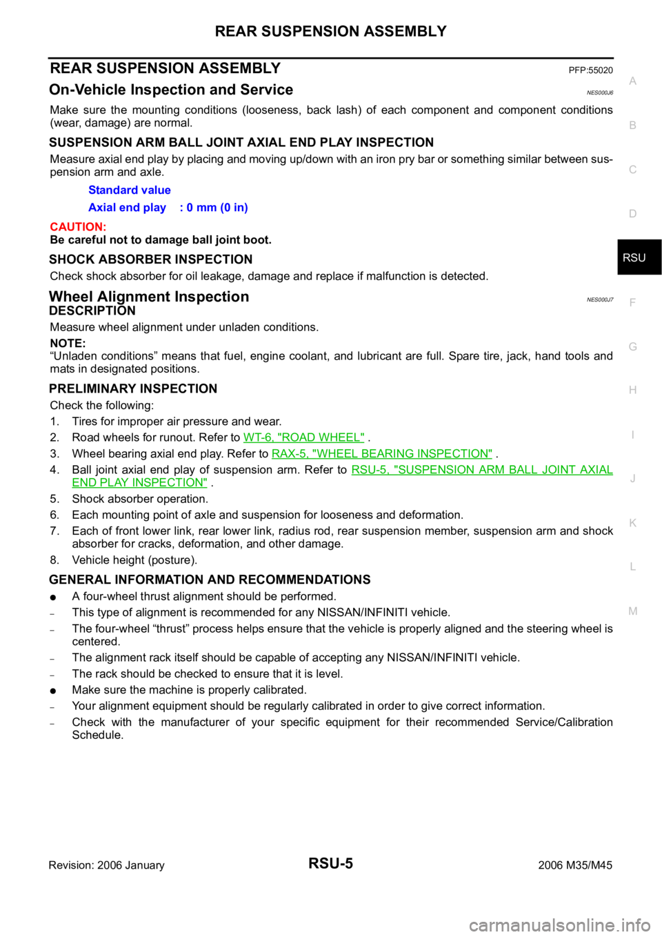
Make sure the mounting conditions (looseness, back lash) of each component and component conditions
(wear, damage) are normal.
SUSPENSION ARM BALL JOINT AXIAL END PLAY INSPECTION
Measure axial end play by placing and moving up/down with an iron pry bar or something similar between sus-
pension arm and axle.
CAUTION:
Be careful not to damage ball joint boot.
SHOCK ABSORBER INSPECTION
Check shock absorber for oil leakage, damage and replace if malfunction is detected.
Wheel Alignment InspectionNES000J7
DESCRIPTION
Measure wheel alignment under unladen conditions.
NOTE:
“Unladen conditions” means that fuel, engine coolant, and lubricant are full. Spare tire, jack, hand tools and
mats in designated positions.
PRELIMINARY INSPECTION
Check the following:
1. Tires for improper air pressure and wear.
2. Road wheels for runout. Refer to WT-6, "
ROAD WHEEL" .
3. Wheel bearing axial end play. Refer to RAX-5, "
WHEEL BEARING INSPECTION" .
4. Ball joint axial end play of suspension arm. Refer to RSU-5, "
SUSPENSION ARM BALL JOINT AXIAL
END PLAY INSPECTION" .
5. Shock absorber operation.
6. Each mounting point of axle and suspension for looseness and deformation.
7. Each of front lower link, rear lower link, radius rod, rear suspension member, suspension arm and shock
absorber for cracks, deformation, and other damage.
8. Vehicle height (posture).
GENERAL INFORMATION AND RECOMMENDATIONS
A four-wheel thrust alignment should be performed.
–This type of alignment is recommended for any NISSAN/INFINITI vehicle.
–The four-wheel “thrust” process helps ensure that the vehicle is properly aligned and the steering wheel is
centered.
–The alignment rack itself should be capable of accepting any NISSAN/INFINITI vehicle.
–The rack should be checked to ensure that it is level.
Make sure the machine is properly calibrated.
–Your alignment equipment should be regularly calibrated in order to give correct information.
–Check with the manufacturer of your specific equipment for their recommended Service/Calibration
Schedule.Standard value
Axial end play : 0 mm (0 in)