2006 INFINITI M35 pressure
[x] Cancel search: pressurePage 3450 of 5621
![INFINITI M35 2006 Factory Service Manual FRONT SUSPENSION ASSEMBLY
FSU-23
[AWD]
C
D
F
G
H
I
J
K
L
MA
B
FSU
Revision: 2006 January2006 M35/M45
FRONT SUSPENSION ASSEMBLYPFP:54010
On-Vehicle Inspection and ServiceNES000IQ
Make sure the mount INFINITI M35 2006 Factory Service Manual FRONT SUSPENSION ASSEMBLY
FSU-23
[AWD]
C
D
F
G
H
I
J
K
L
MA
B
FSU
Revision: 2006 January2006 M35/M45
FRONT SUSPENSION ASSEMBLYPFP:54010
On-Vehicle Inspection and ServiceNES000IQ
Make sure the mount](/manual-img/42/57023/w960_57023-3449.png)
FRONT SUSPENSION ASSEMBLY
FSU-23
[AWD]
C
D
F
G
H
I
J
K
L
MA
B
FSU
Revision: 2006 January2006 M35/M45
FRONT SUSPENSION ASSEMBLYPFP:54010
On-Vehicle Inspection and ServiceNES000IQ
Make sure the mounting conditions (looseness, back lash) of each component and component conditions
(wear, damage) are normal.
INSPECTION OF LOWER BALL JOINT END PLAY
1. Set front wheels in a straight-ahead position. Do not depress brake pedal.
2. Place an iron bar or similar tool between transverse link and steering knuckle.
3. Measure axial end play by prying it up and down.
CAUTION:
Be careful not to damage ball joint boot. Do not damage the installation position by applying
excessive force.
SHOCK ABSORBER INSPECTION
Check for oil leakage, damage and breakage of installation positions.
Wheel Alignment InspectionNES000IR
DESCRIPTION
Measure wheel alignment under unladen conditions.
NOTE:
“Unladen conditions” means that fuel, engine coolant, and lubricant are full. Spare tire, jack, hand tools and
mats are in designated positions.
PRELIMINARY CHECK
Check the following:
1. Tires for improper air pressure and wear.
2. Road wheels for runout. Refer to WT-6, "
ROAD WHEEL" .
3. Wheel bearing axial end play. Refer to FAX-5, "
WHEEL BEARING INSPECTION" .
4. Transverse link ball joint axial end play. Refer to FSU-31, "
INSPECTION AFTER REMOVAL" .
5. Shock absorber operation.
6. Each mounting part of axle and suspension for looseness and deformation.
7. Each of suspension member, shock absorber, upper link and transverse link for cracks, deformation and
other damage.
8. Vehicle height (posture).
GENERAL INFORMATION AND RECOMMENDATIONS
A four-wheel thrust alignment should be performed.
–This type of alignment is recommended for any NISSAN/INFINITI vehicle.
–The four-wheel “thrust” process helps ensure that the vehicle is properly aligned and the steering wheel is
centered.
–The alignment rack itself should be capable of accepting any NISSAN/INFINITI vehicle.
–The rack should be checked to ensure that it is level.
Make sure the machine is properly calibrated.
–Your alignment equipment should be regularly calibrated in order to give correct information.
–Check with the manufacturer of your specific equipment for their recommended Service/Calibration
Schedule.Axial end play : 0 mm (0 in)
Page 3470 of 5621

PRECAUTIONS
GI-7
C
D
E
F
G
H
I
J
K
L
MB
GI
Revision: 2006 January2006 M35/M45
(i.e. Flexible Fuel Vehicle - FFV models). Using a fuel other than that specified could adversely affect
the emission control devices and systems, and could also affect the warranty coverage validity.
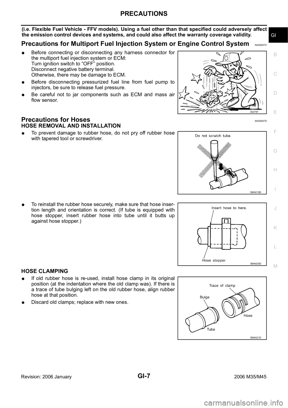
Precautions for Multiport Fuel Injection System or Engine Control SystemNAS0007C
Before connecting or disconnecting any harness connector for
the multiport fuel injection system or ECM:
Turn ignition switch to “OFF” position.
Disconnect negative battery terminal.
Otherwise, there may be damage to ECM.
Before disconnecting pressurized fuel line from fuel pump to
injectors, be sure to release fuel pressure.
Be careful not to jar components such as ECM and mass air
flow sensor.
Precautions for HosesNAS0007D
HOSE REMOVAL AND INSTALLATION
To prevent damage to rubber hose, do not pry off rubber hose
with tapered tool or screwdriver.
To reinstall the rubber hose securely, make sure that hose inser-
tion length and orientation is correct. (If tube is equipped with
hose stopper, insert rubber hose into tube until it butts up
against hose stopper.)
HOSE CLAMPING
If old rubber hose is re-used, install hose clamp in its original
position (at the indentation where the old clamp was). If there is
a trace of tube bulging left on the old rubber hose, align rubber
hose at that position.
Discard old clamps; replace with new ones.
SGI787
SMA019D
SMA020D
SMA021D
Page 3501 of 5621

GI-38
CONSULT-II CHECKING SYSTEM
Revision: 2006 January2006 M35/M45
CONSULT-II CHECKING SYSTEMPFP:00000
DescriptionNAS0007S
CONSULT-II is a hand-held type tester. When it is connected with a diagnostic connector equipped on the
vehicle side, it will communicate with the control unit equipped in the vehicle and then enable various
kinds of diagnostic tests.
Refer to “CONSULT-II Software Operation Manual” for more information.
Function and System Application NAS0007T
x: Applicable
*: NISSAN Anti-Theft System (INFINITI/NISSAN Vehicle Immobilizer System) Diagnostic test
modeFunction
ENGINE
A/T
AIR BAG
METER A/C AMP
BCM
AUTO DRIVE POS.
ABS (Including VDC)
NATS (IVIS/NATS) *
IPDM E/R
ICC
ALL MODE AWD/4WD
INTELLIGENT KEY
LDW
AIR PRESSURE MONITOR
RAS/HICAS
ADAPTIVE LIGHT
PRECRASH SEATBELT
MULTI AV
Work supportThis mode enables a technician to adjust
some devices faster and more accurately by
following the indications on CONSULT-II.x - - - xxx -- x- xxx- x- -
Self-diagnostic
resultsSelf-diagnostic results can be read and
erased quickly.xxxxxxxxxxxxxxxxxx
Trouble diagnos-
tic recordCurrent self-diagnostic results and all trouble
diagnostic records previously stored can be
read.--x---------------
Data monitor Input/Output data in the ECU can be read. x x - x x x x - x xxxxxxxxx
CAN diagnosis
support monitorThe condition of CAN communication line
can be read.xx- xxxx- xxxxxxxxxx
Active testDiagnostic Test Mode in which CONSULT-II
drives some actuators apart from the ECUs
and also shifts some parameters in a speci-
fied range.x- - - xxx -xxxxxxxx- -
DTC & SRT con-
firmationThe results of SRT (System Readiness Test)
and the self-diagnosis status/result can be
confirmed.x- ----------------
DTC work sup-
portThe operating condition to confirm Diagnosis
Trouble Codes can be selected.xx----------------
ECU (ECM/TCM)
part numberECU (ECM/TCM) part number can be read. xx - - xxx -- xxxxxxxxx
ECU discrimi-
nated No.Classification number of a replacement ECU
can be read to prevent an incorrect ECU from
being installed.-- x---------------
Function testThis mode can show results of self-diagnosis
of ECU with either 'OK' or 'NG'. For engines,
more practical tests regarding sensors/
switches and/or actuators are available.xxx---x-----------
Control unit ini-
tializationAll registered ignition key IDs in NATS com-
ponents can be initialized and new IDs can
be registered.-- -----x----------
AV COMM moni-
torThe condition of AV communication can be
Indicated.------------ ---- -x
Page 3516 of 5621

TERMINOLOGY
GI-53
C
D
E
F
G
H
I
J
K
L
MB
GI
Revision: 2006 January2006 M35/M45
TERMINOLOGYPFP:00011
SAE J1930 Terminology List NAS00088
All emission related terms used in this publication in accordance with SAE J1930 are listed. Accordingly, new
terms, new acronyms/abbreviations and old terms are listed in the following chart.
NEW TERMNEW ACRONYM /
ABBREVIATIONOLD TERM
Air cleaner ACL Air cleaner
Barometric pressure BARO ***
Barometric pressure sensor-BCDD BAROS-BCDD BCDD
Camshaft position CMP ***
Camshaft position sensor CMPS Crank angle sensor
Canister *** Canister
Carburetor CARB Carburetor
Charge air cooler CAC Intercooler
Closed loop CL Closed loop
Closed throttle position switch CTP switch Idle switch
Clutch pedal position switch CPP switch Clutch switch
Continuous fuel injection system CFI system ***
Continuous trap oxidizer system CTOX system ***
Crankshaft position CKP ***
Crankshaft position sensor CKPS ***
Data link connector DLC ***
Data link connector for CONSULT-II DLC for CONSULT-II Diagnostic connector for CONSULT-II
Diagnostic test mode DTM Diagnostic mode
Diagnostic test mode selector DTM selector Diagnostic mode selector
Diagnostic test mode I DTM I Mode I
Diagnostic test mode II DTM II Mode II
Diagnostic trouble code DTC Malfunction code
Direct fuel injection system DFI system ***
Distributor ignition system DI system Ignition timing control
Early fuel evaporation-mixture heater EFE-mixture heater Mixture heater
Early fuel evaporation system EFE system Mixture heater control
Electrically erasable programmable read
only memoryEEPROM ***
Electronic ignition system EI system Ignition timing control
Engine control EC ***
Engine control module ECM ECCS control unit
Engine coolant temperature ECT Engine temperature
Engine coolant temperature sensor ECTS Engine temperature sensor
Engine modification EM ***
Engine speed RPM Engine speed
Erasable programmable read only memory EPROM ***
Evaporative emission canister EVAP canister Canister
Evaporative emission system EVAP system Canister control solenoid valve
Exhaust gas recirculation valve EGR valve EGR valve
Page 3517 of 5621

GI-54
TERMINOLOGY
Revision: 2006 January2006 M35/M45
Exhaust gas recirculation control-BPT
valveEGRC-BPT valve BPT valve
Exhaust gas recirculation control-solenoid
valveEGRC-solenoid valve EGR control solenoid valve
Exhaust gas recirculation temperature sen-
sor
EGRT sensor Exhaust gas temperature sensor
EGR temperature sensor
Flash electrically erasable programmable
read only memoryFEEPROM ***
Flash erasable programmable read only
memoryFEPROM ***
Flexible fuel sensor FFS ***
Flexible fuel system FF system ***
Fuel pressure regulator *** Pressure regulator
Fuel pressure regulator control solenoid
valve*** PRVR control solenoid valve
Fuel trim FT ***
Heated Oxygen sensor HO2S Exhaust gas sensor
Idle air control system IAC system Idle speed control
Idle air control valve-air regulator IACV-air regulator Air regulator
Idle air control valve-auxiliary air control
valveIACV-AAC valve Auxiliary air control (AAC) valve
Idle air control valve-FICD solenoid valve IACV-FICD solenoid valve FICD solenoid valve
Idle air control valve-idle up control sole-
noid valveIACV-idle up control solenoid valve Idle up control solenoid valve
Idle speed control-FI pot ISC-FI pot FI pot
Idle speed control system ISC system ***
Ignition control IC ***
Ignition control module ICM ***
Indirect fuel injection system IFI system ***
Intake air IA Air
Intake air temperature sensor IAT sensor Air temperature sensor
Knock *** Detonation
Knock sensor KS Detonation sensor
Malfunction indicator lamp MIL Check engine light
Manifold absolute pressure MAP ***
Manifold absolute pressure sensor MAPS ***
Manifold differential pressure MDP ***
Manifold differential pressure sensor MDPS ***
Manifold surface temperature MST ***
Manifold surface temperature sensor MSTS ***
Manifold vacuum zone MVZ ***
Manifold vacuum zone sensor MVZS ***
Mass air flow sensor MAFS Air flow meter
Mixture control solenoid valve MC solenoid valve Air-fuel ratio control solenoid valve
Multiport fuel injection System MFI system Fuel injection controlNEW TERMNEW ACRONYM /
ABBREVIATIONOLD TERM
Page 3531 of 5621

GW-12
WINDSHIELD GLASS
Revision: 2006 January2006 M35/M45
4. Remove the cowl top cover. Refer to EI-18, "COWL TOP" .
5. Remove roof side molding. Refer to EI-25, "
ROOF SIDE MOLDING" .
6. Apply a protective tape around the windshield glass to protect the painted surface from damage.
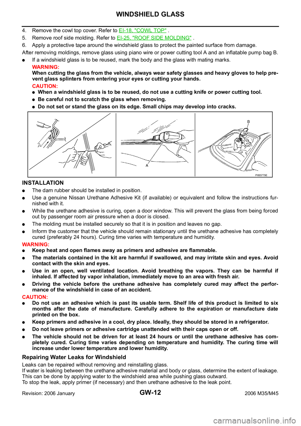
After removing moldings, remove glass using piano wire or power cutting tool A and an inflatable pump bag B.
If a windshield glass is to be reused, mark the body and the glass with mating marks.
WA R N I N G :
When cutting the glass from the vehicle, always wear safety glasses and heavy gloves to help pre-
vent glass splinters from entering your eyes or cutting your hands.
CAUTION:
When a windshield glass is to be reused, do not use a cutting knife or power cutting tool.
Be careful not to scratch the glass when removing.
Do not set or stand the glass on its edge. Small chips may develop into cracks.
INSTALLATION
The dam rubber should be installed in position.
Use a genuine Nissan Urethane Adhesive Kit (if available) or equivalent and follow the instructions fur-
nished with it.
While the urethane adhesive is curing, open a door window. This will prevent the glass from being forced
out by passenger room air pressure when a door is closed.
The molding must be installed securely so that it is in position and leaves no gap.
Inform the customer that the vehicle should remain stationary until the urethane adhesive has completely
cured (preferably 24 hours). Curing time varies with temperature and humidity.
WAR NING :
Keep heat and open flames away as primers and adhesive are flammable.
The materials contained in the kit are harmful if swallowed, and may irritate skin and eyes. Avoid
contact with the skin and eyes.
Use in an open, well ventilated location. Avoid breathing the vapors. They can be harmful if
inhaled. If affected by vapor inhalation, immediately move to an area with fresh air.
Driving the vehicle before the urethane adhesive has completely cured may affect the perfor-
mance of the windshield in case of an accident.
CAUTION:
Do not use an adhesive which is past its usable term. Shelf life of this product is limited to six
months after the date of manufacture. Carefully adhere to the expiration or manufacture date
printed on the box.
Keep primers and adhesive in a cool, dry place. Ideally, they should be stored in a refrigerator.
Do not leave primers or adhesive cartridge unattended with their caps open or off.
The vehicle should not be driven for at least 24 hours or until the urethane adhesive has com-
pletely cured. Curing time varies depending on temperature and humidity. The curing time will
increase under lower temperature and lower humidity.
Repairing Water Leaks for Windshield
Leaks can be repaired without removing and reinstalling glass.
If water is leaking between the urethane adhesive material and body or glass, determine the extent of leakage.
This can be done by applying water to the windshield area while pushing glass outward.
To stop the leak, apply primer (if necessary) and then urethane adhesive to the leak point.
PIIB5779E
Page 3579 of 5621

GW-60
SIDE WINDOW GLASS
Revision: 2006 January2006 M35/M45
INSTALLATION
Use a genuine Nissan Urethane Adhesive Kit (if available) or equivalent and follow the instructions fur-
nished with it.
While the urethane adhesive is curing, open a door window. This will prevent the glass from being forced
out by passenger room air pressure when a door is closed.
The molding must be installed securely so that it is in position and leaves no gap.
Inform the customer that the vehicle should remain stationary until the urethane adhesive has completely
cured (preferably 24 hours). Curing time varies with temperature and humidity.
WAR NING :
Keep heat and open flames away as primers and adhesive are flammable.
The materials contained in the kit are harmful if swallowed, and may irritate skin and eyes. Avoid
contact with the skin and eyes.
Use in an open, well ventilated location. Avoid breathing the vapors. They can be harmful if
inhaled. If affected by vapor inhalation, immediately move to an area with fresh air.
Driving the vehicle before the urethane adhesive has completely cured may affect the perfor-
mance of the side window in case of an accident.
CAUTION:
Do not use an adhesive which is past its usable term. Shelf life of this product is limited to six
months after the date of manufacture. Carefully adhere to the expiration or manufacture date
printed on the box.
Keep primers and adhesive in a cool, dry place. Ideally, they should be stored in a refrigerator.
Do not leave primers or adhesive cartridge unattended with their caps open or off.
The vehicle should not be driven for at least 24 hours or until the urethane adhesive has com-
pletely cured. Curing time varies depending on temperature and humidity. The curing time will
increase under lower temperature and lower humidity.
Repairing Water Leaks
Leaks can be repaired without removing and reinstalling glass.
If water is leaking between the urethane adhesive material and body or glass, determine the extent of leakage.
This can be done by applying water to the side window area while pushing glass outward.
To stop the leak, apply primer (if necessary) and then urethane adhesive to the leak point.
Page 3581 of 5621

GW-62
REAR WINDOW GLASS AND MOLDING
Revision: 2006 January2006 M35/M45
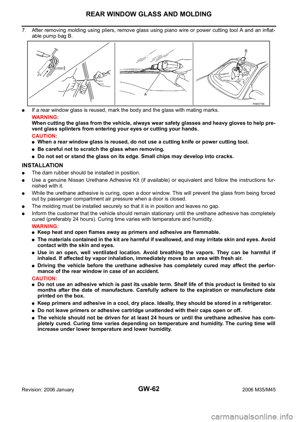
7. After removing molding using pliers, remove glass using piano wire or power cutting tool A and an inflat-
able pump bag B.
If a rear window glass is reused, mark the body and the glass with mating marks.
WA R N I N G :
When cutting the glass from the vehicle, always wear safety glasses and heavy gloves to help pre-
vent glass splinters from entering your eyes or cutting your hands.
CAUTION:
When a rear window glass is reused, do not use a cutting knife or power cutting tool.
Be careful not to scratch the glass when removing.
Do not set or stand the glass on its edge. Small chips may develop into cracks.
INSTALLATION
The dam rubber should be installed in position.
Use a genuine Nissan Urethane Adhesive Kit (if available) or equivalent and follow the instructions fur-
nished with it.
While the urethane adhesive is curing, open a door window. This will prevent the glass from being forced
out by passenger compartment air pressure when a door is closed.
The molding must be installed securely so that it is in position and leaves no gap.
Inform the customer that the vehicle should remain stationary until the urethane adhesive has completely
cured (preferably 24 hours). Curing time varies with temperature and humidity.
WA R N I N G :
Keep heat and open flames away as primers and adhesive are flammable.
The materials contained in the kit are harmful if swallowed, and may irritate skin and eyes. Avoid
contact with the skin and eyes.
Use in an open, well ventilated location. Avoid breathing the vapors. They can be harmful if
inhaled. If affected by vapor inhalation, immediately move to an area with fresh air.
Driving the vehicle before the urethane adhesive has completely cured may affect the perfor-
mance of the rear window in case of an accident.
CAUTION:
Do not use an adhesive which is past its usable term. Shelf life of this product is limited to six
months after the date of manufacture. Carefully adhere to the expiration or manufacture date
printed on the box.
Keep primers and adhesive in a cool, dry place. Ideally, they should be stored in a refrigerator.
Do not leave primers or adhesive cartridge unattended with their caps open or off.
The vehicle should not be driven for at least 24 hours or until the urethane adhesive has com-
pletely cured. Curing time varies depending on temperature and humidity. The curing time will
increase under lower temperature and lower humidity.
PIIB5779E