2006 INFINITI M35 warning
[x] Cancel search: warningPage 1027 of 5621

BL-88
INTELLIGENT KEY SYSTEM
Revision: 2006 January2006 M35/M45
TRUNK OPEN FUNCTION MALFUNCTION
NOTE:
Before performing the diagnosis in the following table, check “Trouble Diagnosis Procedure”. Refer to BL-
78, "Trouble Diagnosis Procedure" .
Make sure that vehicle is under the condition shown in “Conditions of vehicle” before starting diagnosis,
and check each symptom.
If the following “symptoms” are detected, check systems shown in the “Diagnosis/service procedure” col-
umn in this order.
Conditions of Vehicle (Operating Conditions)
Intelligent Key is out of key slot.
All doors are closed.
Panic alarm function does not operate.1. Check “PANIC ALARM DELAY” setting in “WORK SUPPORT”.BL-83
2. Check theft warning operation.BL-220
3. Check Intelligent Key battery inspection.BL-126
4. Check key slot.BL-94
5. Replace Intelligent Key unit.BL-125
Symptom Diagnosis/service procedureReference
page
Symptom Diagnosis/service procedure Reference page
Trunk open function does not operate by trunk
opener request switch.1. Check trunk opener request switch.BL-103
2. Check trunk lid opener cancel switch.BL-121
3. Check outside key antenna (trunk room).BL-110
4. Replace Intelligent Key unit.BL-125
Trunk open function does not operate by Intelli-
gent Key.1.Check “TRUNK OPEN DELAY” setting in “WORK
SUPPORT”.BL-832. Check trunk lid opener system.BL-209
3. Check trunk room lamp switch.BL-99
4. Check Intelligent Key battery inspection.BL-126
5. Replace Intelligent Key unit.BL-125
Key reminder function does not operate.1. Check door switch.BL-96
2. Check trunk room lamp switch.BL-99
3. Check inside key antenna (trunk room).BL-112
4. Check trunk lid opener system.BL-209
5. Replace Intelligent Key unit.BL-125
Page 1028 of 5621
INTELLIGENT KEY SYSTEM
BL-89
C
D
E
F
G
H
J
K
L
MA
B
BL
Revision: 2006 January2006 M35/M45
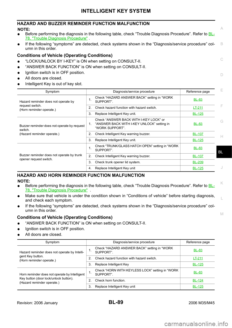
HAZARD AND BUZZER REMINDER FUNCTION MALFUNCTION
NOTE:
Before performing the diagnosis in the following table, check “Trouble Diagnosis Procedure”. Refer to BL-
78, "Trouble Diagnosis Procedure" .
If the following “symptoms” are detected, check systems shown in the “Diagnosis/service procedure” col-
umn in this order.
Conditions of Vehicle (Operating Conditions)
“LOCK/UNLOCK BY I-KEY” is ON when setting on CONSULT-II.
“ANSWER BACK FUNCTION” is ON when setting on CONSULT-II.
Ignition switch is in OFF position.
All doors are closed.
Intelligent Key is out of key slot.
HAZARD AND HORN REMINDER FUNCTION MALFUNCTION
NOTE:
Before performing the diagnosis in the following table, check “Trouble Diagnosis Procedure”. Refer to BL-
78, "Trouble Diagnosis Procedure" .
Make sure that vehicle is under the condition shown in “Conditions of vehicle” before starting diagnosis,
and check each symptom.
If the following “symptoms” are detected, check systems shown in the “Diagnosis/service procedure” col-
umn in this order.
Conditions of Vehicle (Operating Conditions)
“ANSWER BACK FUNCTION” is ON when setting on CONSULT-II.
Ignition switch is in OFF position.
All doors are closed.
Symptom Diagnosis/service procedure Reference page
Hazard reminder does not operate by
request switch.
(Horn reminder operate.)1.Check “HAZARD ANSWER BACK” setting in “WORK
SUPPORT”.BL-83
2. Check hazard function with hazard switch.LT- 2 11
3. Replace Intelligent Key unit.BL-125
Buzzer reminder does not operate by request
switch.
(Hazard reminder operate.)1.Check “ANSWER BACK WITH I-KEY LOCK” or
“ANSWER BACK WITH I-KEY UNLOCK” setting in
“WORK SUPPORT”.BL-83
2. Check Intelligent Key warning buzzer.BL-107
3. Replace Intelligent Key unit.BL-125
Buzzer reminder does not operate by trunk
opener request switch.1.Check “TRUNK/GLASS HATCH OPEN” setting in “WORK
SUPPORT”.BL-832. Check Intelligent Key warning buzzer.BL-107
3. Check trunk opener lid system.BL-209
4. Replace Intelligent Key unitBL-125
Symptom Diagnosis/service procedure Reference page
Hazard reminder does not operate by Intelli-
gent Key button.
(Horn reminder operate.)1.Check “HAZARD ANSWER BACK” setting in “WORK
SUPPORT”.BL-83
2. Check hazard function with hazard switch.LT- 2 11
3. Replace Intelligent KeyBL-125
Horn reminder does not operate by Intelligent
Key button (door lock/unlock button).
(Hazard reminder operate.)1.Check “HORN WITH KEYLESS LOCK” setting in “WORK
SUPPORT”.BL-83
2. Check horn function.BL-124
3. Replace Intelligent Key unitBL-125
Page 1029 of 5621

BL-90
INTELLIGENT KEY SYSTEM
Revision: 2006 January2006 M35/M45
POWER WINDOW DOWN FUNCTION MALFUNCTION
NOTE:
Before performing the diagnosis in the following table, check “Trouble Diagnosis Procedure”. Refer to BL-
78, "Trouble Diagnosis Procedure" .
If the following “symptoms” are detected, check systems shown in the “Diagnoses/service procedure” col-
umn in this order.
Conditions of Vehicle (Operating Conditions)
Ignition switch is in OFF or ACC position.
Retaind power operation does not operate. Refer to GW-16, "RETAINED POWER OPERATION" .
WARNING FUNCTION MALFUNCTION
NOTE:
Before performing the diagnosis in the following table, check “Trouble Diagnosis Procedure”. Refer to BL-
78, "Trouble Diagnosis Procedure" .
Make sure that vehicle is under the condition shown in “Conditions of vehicle” before starting diagnosis,
and check each symptom.
If the following “symptoms” are detected, check systems shown in the “Diagnosis/service procedure” col-
umn in this order.
Conditions of Vehicle (Operating Conditions)
Warning chime functions operating condition is extremely complicated, during operating confirmations, recon-
firm the list above twice in order to ensure proper operation.
Symptom Diagnosis/service procedure Reference page
Power window down function does not
operate.1. Check “P/W DOWN DELAY” setting in “WORK SUPPORT”.BL-83
2. Check Intelligent Key battery inspection.BL-126
Symptom Diagnosis/service procedure Reference page
OFF position warn-
ing does not oper-
ate.For internal1. Check ignition switch position.BL-117
2. Check door switch.BL-96
3. Check warning chime function.BL-125
4. Replace Intelligent Key unit.BL-125
For external1. Check ignition switch position.BL-1172. Check door switch.BL-96
3. Check Intelligent Key warning buzzer.BL-107
4. Replace Intelligent Key unit.BL-125
P position warning does not operate.1. Check Park position switch.BL-115
2. Check door switch.BL-96
3. Check Intelligent Key warning buzzer.BL-107
4. Check warning chime function.BL-125
5. Check combination meter display.BL-124
6. Replace Intelligent Key unit. BL-125
ACC warning does not operate1. Check ignition switch position.BL-1172. Check warning chime function.BL-125
3. Check combination meter display.BL-124
4. Replace Intelligent Key unit.BL-125
Page 1030 of 5621
INTELLIGENT KEY SYSTEM
BL-91
C
D
E
F
G
H
J
K
L
MA
B
BL
Revision: 2006 January2006 M35/M45
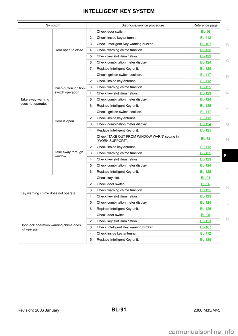
Take away warning
does not operate.Door open to close1. Check door switch.BL-96
2. Check inside key antenna.BL-112
3. Check Intelligent Key warning buzzer.BL-107
4. Check warning chime function.BL-125
5. Check key slot illumination.BL-123
6. Check combination meter display.BL-124
7. Replace Intelligent Key unit. BL-125
Push-button ignition
switch operation1. Check ignition switch position.BL-117
2. Check inside key antenna.BL-112
3. Check warning chime function.BL-125
4. Check key slot illumination.BL-123
5. Check combination meter display.BL-124
6. Replace Intelligent Key unit. BL-125
Door is open1. Check ignition switch position.BL-1172. Check inside key antenna.BL-112
3. Check combination meter display.BL-124
4. Replace Intelligent Key unit. BL-125
Take away through
window1.Check “TAKE OUT FROM WINDOW WARN” setting in
“WORK SUPPORT”.BL-83
2. Check inside key antenna.BL-112
3. Check warning chime function.BL-125
4. Check key slot illumination.BL-123
5. Check combination meter display.BL-124
6. Replace Intelligent Key unit. BL-125
Key warning chime does not operate.1. Check key slot.BL-94
2. Check door switch.BL-96
3. Check warning chime function.BL-125
4. Check key slot illumination.BL-123
5. Check combination meter display.BL-124
6. Replace Intelligent Key unit. BL-125
Door lock operation warning chime does
not operate.1. Check door switch.BL-96
2. Check key slot illumination.BL-123
3. Check Intelligent Key warning buzzer.BL-107
4. Check inside key antenna.BL-112
5. Replace Intelligent Key unit. BL-125
Symptom Diagnosis/service procedure Reference page
Page 1046 of 5621

INTELLIGENT KEY SYSTEM
BL-107
C
D
E
F
G
H
J
K
L
MA
B
BL
Revision: 2006 January2006 M35/M45
Check Intelligent Key Warning BuzzerNIS001XT
1. CHECK INTELLIGENT KEY WARNING BUZZER
Check voltage between Intelligent Key unit connector and ground.
OK or NG
OK >> Intelligent Key warning buzzer is OK.
NG >> GO TO 2.
2. CHECK INTELLIGENT KEY WARNING BUZZER POWER SUPPLY CIRCUIT
1. Turn ignition switch OFF.
2. Disconnect Intelligent Key warning buzzer connector.
3. Check voltage between Intelligent Key warning buzzer connector and ground.
OK or NG
OK >> GO TO 3.
NG >> Repair or replace Intelligent Key warning buzzer power
supply circuit.
3. CHECK INTELLIGENT KEY WARNING BUZZER CIRCUIT
1. Disconnect Intelligent Key unit connector.
2. Check continuity between Intelligent Key unit connector and Intelligent Key warning buzzer connector.
3. Check continuity between Intelligent Key unit connector and
ground.
OK or NG
OK >> GO TO 4.
NG >> Repair or replace harness between Intelligent Key unit and Intelligent Key warning buzzer.
Te r m i n a l s
Warning
buzzer opera-
tion conditionVoltage (V)
(Approx.) (+)
(–)
Intelligent Key
unit connectorTerminal
M33 55 GroundYe s 0
No Battery voltage
PIIB6341E
Terminals
Voltage (V)
(Approx.) (+)
(–) Intelligent Key
warning buzzer
connectorTerminal
E37 3 Ground Battery voltage
PIIB6342E
AB
Continuity
Intelligent Key
unit connectorTerminalIntelligent Key
warning buzzer
connectorTerminal
M33 55 E37 1 Yes
A
GroundContinuity
Intelligent Key unit
connectorTerminal
M33 55 No
PIIB6343E
Page 1047 of 5621
BL-108
INTELLIGENT KEY SYSTEM
Revision: 2006 January2006 M35/M45
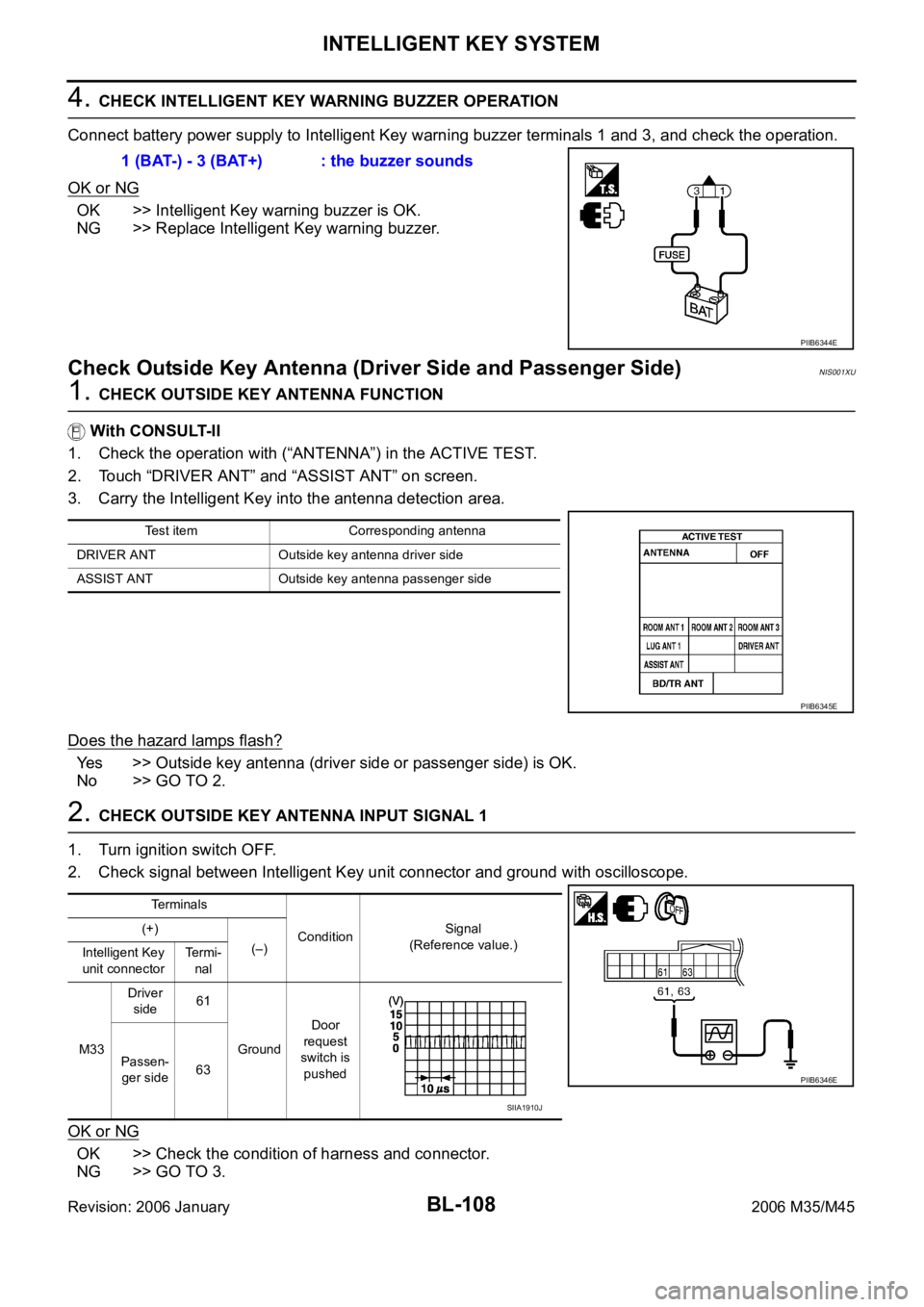
4. CHECK INTELLIGENT KEY WARNING BUZZER OPERATION
Connect battery power supply to Intelligent Key warning buzzer terminals 1 and 3, and check the operation.
OK or NG
OK >> Intelligent Key warning buzzer is OK.
NG >> Replace Intelligent Key warning buzzer.
Check Outside Key Antenna (Driver Side and Passenger Side)NIS001XU
1. CHECK OUTSIDE KEY ANTENNA FUNCTION
With CONSULT-II
1. Check the operation with (“ANTENNA”) in the ACTIVE TEST.
2. Touch “DRIVER ANT” and “ASSIST ANT” on screen.
3. Carry the Intelligent Key into the antenna detection area.
Does the hazard lamps flash?
Yes >> Outside key antenna (driver side or passenger side) is OK.
No >> GO TO 2.
2. CHECK OUTSIDE KEY ANTENNA INPUT SIGNAL 1
1. Turn ignition switch OFF.
2. Check signal between Intelligent Key unit connector and ground with oscilloscope.
OK or NG
OK >> Check the condition of harness and connector.
NG >> GO TO 3.1 (BAT-) - 3 (BAT+) : the buzzer sounds
PIIB6344E
Test item Corresponding antenna
DRIVER ANT Outside key antenna driver side
ASSIST ANT Outside key antenna passenger side
PIIB6345E
Te r m i n a l s
ConditionSignal
(Reference value.) (+)
(–)
Intelligent Key
unit connectorTermi-
nal
M33Driver
side61
GroundDoor
request
switch is
pushed Passen-
ger side63
PIIB6346E
SIIA1910J
Page 1063 of 5621
BL-124
INTELLIGENT KEY SYSTEM
Revision: 2006 January2006 M35/M45
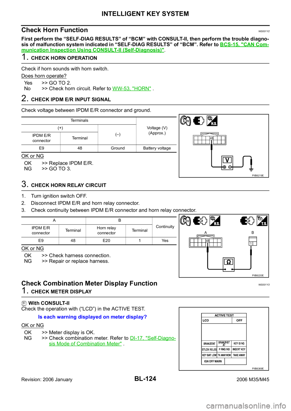
Check Horn FunctionNIS001Y2
First perform the “SELF-DIAG RESULTS” of “BCM” with CONSULT-II, then perform the trouble diagno-
sis of malfunction system indicated in “SELF-DIAG RESULTS” of “BCM”. Refer to BCS-15, "
CAN Com-
munication Inspection Using CONSULT-II (Self-Diagnosis)".
1. CHECK HORN OPERATION
Check if horn sounds with horn switch.
Does horn operate?
Yes >> GO TO 2.
No >> Check horn circuit. Refer to WW-53, "
HORN" .
2. CHECK IPDM E/R INPUT SIGNAL
Check voltage between IPDM E/R connector and ground.
OK or NG
OK >> Replace IPDM E/R.
NG >> GO TO 3.
3. CHECK HORN RELAY CIRCUIT
1. Turn ignition switch OFF.
2. Disconnect IPDM E/R and horn relay connector.
3. Check continuity between IPDM E/R connector and horn relay connector.
OK or NG
OK >> Check harness connection.
NG >> Repair or replace harness.
Check Combination Meter Display FunctionNIS001Y3
1. CHECK METER DISPLAY
With CONSULT-II
Check the operation with (“LCD”) in the ACTIVE TEST.
OK or NG
OK >> Meter display is OK.
NG >> Check combination meter. Refer to DI-17, "
Self-Diagno-
sis Mode of Combination Meter" .
Terminals
Voltage (V)
(Approx.) (+)
(–)
IPDM E/R
connectorTerminal
E9 48 Ground Battery voltage
PIIB6219E
AB
Continuity
IPDM E/R
connectorTe r m i n a lHorn relay
connectorTerminal
E9 48 E20 1 Yes
PIIB6220E
Is each warning displayed on meter display?
PIIB6369E
Page 1064 of 5621
INTELLIGENT KEY SYSTEM
BL-125
C
D
E
F
G
H
J
K
L
MA
B
BL
Revision: 2006 January2006 M35/M45
Check Warning Chime FunctionNIS001Y4
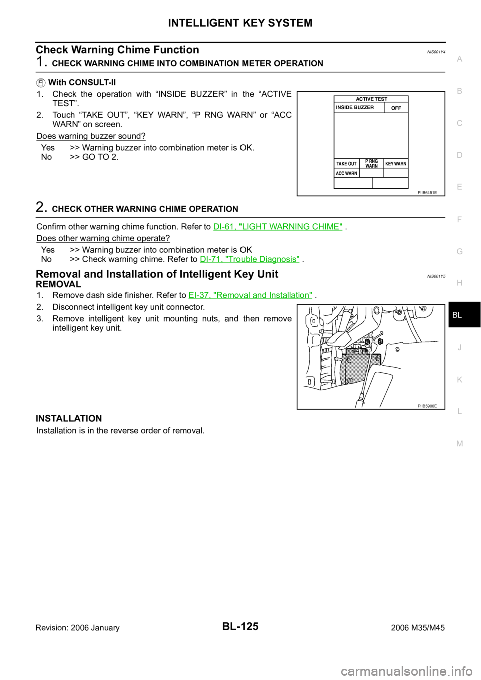
1. CHECK WARNING CHIME INTO COMBINATION METER OPERATION
With CONSULT-II
1. Check the operation with “INSIDE BUZZER” in the “ACTIVE
TEST”.
2. Touch “TAKE OUT”, “KEY WARN”, “P RNG WARN” or “ACC
WARN” on screen.
Does warning buzzer sound?
Yes >> Warning buzzer into combination meter is OK.
No >> GO TO 2.
2. CHECK OTHER WARNING CHIME OPERATION
Confirm other warning chime function. Refer to DI-61, "
LIGHT WARNING CHIME" .
Does other warning chime operate?
Yes >> Warning buzzer into combination meter is OK
No >> Check warning chime. Refer to DI-71, "
Trouble Diagnosis" .
Removal and Installation of Intelligent Key UnitNIS001Y5
REMOVAL
1. Remove dash side finisher. Refer to EI-37, "Removal and Installation" .
2. Disconnect intelligent key unit connector.
3. Remove intelligent key unit mounting nuts, and then remove
intelligent key unit.
INSTALLATION
Installation is in the reverse order of removal.
PIIB6451E
PIIB5900E