2006 INFINITI M35 ABS
[x] Cancel search: ABSPage 4425 of 5621
![INFINITI M35 2006 Factory Service Manual LAN-756
[CAN]
CAN SYSTEM (TYPE 15)
Revision: 2006 January2006 M35/M45
17. CHECK HARNESS FOR SHORT CIRCUIT
Check continuity between driver seat control unit harness connector
terminals and ground.
OK o INFINITI M35 2006 Factory Service Manual LAN-756
[CAN]
CAN SYSTEM (TYPE 15)
Revision: 2006 January2006 M35/M45
17. CHECK HARNESS FOR SHORT CIRCUIT
Check continuity between driver seat control unit harness connector
terminals and ground.
OK o](/manual-img/42/57023/w960_57023-4424.png)
LAN-756
[CAN]
CAN SYSTEM (TYPE 15)
Revision: 2006 January2006 M35/M45
17. CHECK HARNESS FOR SHORT CIRCUIT
Check continuity between driver seat control unit harness connector
terminals and ground.
OK or NG
OK >> GO TO 18.
NG >> Repair harness between driver seat control unit and har-
ness connector B202.
18. CHECK HARNESS FOR SHORT CIRCUIT
1. Disconnect following connectors.
–ABS actuator and electric unit (control unit) connector
–ICC sensor integrated unit connector
–IPDM E/R connector
2. Check continuity between IPDM E/R harness connector termi-
nals.
OK or NG
OK >> GO TO 19.
NG >> Check the following harnesses. If any harness is dam-
aged, repair the harness.
Harness between IPDM E/R and harness connector
E105
Harness between IPDM E/R and ABS actuator and electric unit (control unit)
Harness between IPDM E/R and ICC sensor integrated unit
19. CHECK HARNESS FOR SHORT CIRCUIT
Check continuity between IPDM E/R harness connector terminals
and ground.
OK or NG
OK >> GO TO 20.
NG >> Check the following harnesses. If any harness is dam-
aged, repair the harness.
Harness between IPDM E/R and harness connector E105
Harness between IPDM E/R and ABS actuator and electric unit (control unit)
Harness between IPDM E/R and ICC sensor integrated unit
Driver seat control
unit connectorTerminal
GroundContinuity
B2043No
19 No
SKIA5025E
IPDM E/R
connectorTerminal Continuity
E9 49 50 No
PKIC0290E
IPDM E/R
connectorTerminal
GroundContinuity
E949 No
50 No
PKIC0294E
Page 4427 of 5621
![INFINITI M35 2006 Factory Service Manual LAN-758
[CAN]
CAN SYSTEM (TYPE 15)
Revision: 2006 January2006 M35/M45
22. CHECK UNIT REPRODUCIBILITY
Performs the following procedure for each unit, and then perform reproducibility test.
1. Turn igni INFINITI M35 2006 Factory Service Manual LAN-758
[CAN]
CAN SYSTEM (TYPE 15)
Revision: 2006 January2006 M35/M45
22. CHECK UNIT REPRODUCIBILITY
Performs the following procedure for each unit, and then perform reproducibility test.
1. Turn igni](/manual-img/42/57023/w960_57023-4426.png)
LAN-758
[CAN]
CAN SYSTEM (TYPE 15)
Revision: 2006 January2006 M35/M45
22. CHECK UNIT REPRODUCIBILITY
Performs the following procedure for each unit, and then perform reproducibility test.
1. Turn ignition switch OFF.
2. Disconnect the battery cable from the negative terminal.
3. Disconnect the unit connector.
4. Connect the battery cable to the negative terminal.
5. Make sure that the symptom filled in the “Symptom” of the check sheet is reproduced. (Do not confuse it
with the symptom related to removed unit.)
6. Make sure that the same symptom is reproduced.
–A/T assembly
–AWD control unit
–AFS control unit
–BCM
–LDW camera unit
–Low tire pressure warning control unit
–Steering angle sensor
–Intelligent Key unit
–Unified meter and A/C amp.
–NAVI control unit
–Pre-crash seat belt control unit
–Driver seat control unit
–ABS actuator and electric unit (control unit)
–ICC sensor integrated unit
–ECM
–IPDM E/R
Check results
Reproduce>>Install removed unit, and then check the other unit.
Not reproduced>>Replace removed unit.
IPDM E/R Ignition Relay Circuit InspectionNKS00484
Check the following. If no malfunction is found, replace the IPDM E/R.
IPDM E/R power supply circuit. Refer to PG-30, "Check IPDM E/R Power Supply and Ground Circuit" .
Ignition power supply circuit. Refer to PG-12, "IGNITION POWER SUPPLY — IGNITION SW. IN “ON”
AND/OR “START”" .
Page 4753 of 5621
![INFINITI M35 2006 Factory Service Manual LU-10
[VQ35DE]
OIL FILTER
Revision: 2006 January2006 M35/M45
OIL FILTERPFP:15208
Removal and InstallationNBS004PY
REMOVAL
1. Remove front engine undercover with power tool.
2. Using oil filter wrench INFINITI M35 2006 Factory Service Manual LU-10
[VQ35DE]
OIL FILTER
Revision: 2006 January2006 M35/M45
OIL FILTERPFP:15208
Removal and InstallationNBS004PY
REMOVAL
1. Remove front engine undercover with power tool.
2. Using oil filter wrench](/manual-img/42/57023/w960_57023-4752.png)
LU-10
[VQ35DE]
OIL FILTER
Revision: 2006 January2006 M35/M45
OIL FILTERPFP:15208
Removal and InstallationNBS004PY
REMOVAL
1. Remove front engine undercover with power tool.
2. Using oil filter wrench (SST), remove oil filter.
CAUTION:
Oil filter is provided with relief valve. Use Genuine Nissan
Oil Filter or equivalent.
Be careful not to get burned when engine and engine oil
may be hot.
When removing, prepare a shop cloth to absorb any
engine oil leakage or spillage.
Do not allow engine oil to adhere to drive belts.
Completely wipe off any engine oil that adheres to engine
and vehicle.
INSTALLATION
1. Remove foreign materials adhering to oil filter installation surface.
2. Apply engine oil to the oil seal contact surface of new oil filter.
3. Screw oil filter manually until it touches the installation surface,
then tighten it by 2/3 turn. Or tighten to the specification.
INSPECTION AFTER INSTALLATION
1. Check the engine oil level. Refer to LU-7, "ENGINE OIL" .
2. Start the engine, and check there is no leak of engine oil.
SBIA0454E
SBIA0455E
SMA010
Oil filter:
: 17.7 Nꞏm (1.8 kg-m, 13 ft-lb)
SMA229B
Page 4772 of 5621
![INFINITI M35 2006 Factory Service Manual OIL FILTER
LU-29
[VK45DE]
C
D
E
F
G
H
I
J
K
L
MA
LU
Revision: 2006 January2006 M35/M45
OIL FILTERPFP:15208
Removal and InstallationNBS004QE
REMOVAL
1. Remove front engine undercover with power tool.
2 INFINITI M35 2006 Factory Service Manual OIL FILTER
LU-29
[VK45DE]
C
D
E
F
G
H
I
J
K
L
MA
LU
Revision: 2006 January2006 M35/M45
OIL FILTERPFP:15208
Removal and InstallationNBS004QE
REMOVAL
1. Remove front engine undercover with power tool.
2](/manual-img/42/57023/w960_57023-4771.png)
OIL FILTER
LU-29
[VK45DE]
C
D
E
F
G
H
I
J
K
L
MA
LU
Revision: 2006 January2006 M35/M45
OIL FILTERPFP:15208
Removal and InstallationNBS004QE
REMOVAL
1. Remove front engine undercover with power tool.
2. Using the oil filter wrench (SST), remove the oil filter.
CAUTION:
Oil filter is provided with relief valve. Use Genuine Nissan
Oil Filter or equivalent.
Be careful not to get burned when engine and engine oil
may be hot.
When removing, prepare a shop cloth to absorb any
engine oil leakage or spillage.
Do not allow engine oil to adhere to drive belts.
Completely wipe off any engine oil that adhere to engine
and vehicle.
INSTALLATION
1. Remove foreign materials adhering to oil filter installation surface.
2. Apply new engine oil to the oil seal circumference of the new oil
filter.
3. Screw oil filter manually until it touches the installation surface,
then tighten it by 2/3 turn. Or tighten to specification.
INSPECTION AFTER INSTALLATION
1. Check the engine oil level. Refer to LU-26, "ENGINE OIL" .
2. Start engine, and check there is no leaks of engine oil.
3. Stop engine and wait for 15 minutes.
4. Check the engine oil level and adjust engine oil. Refer to LU-26, "
ENGINE OIL" .
PBIC1525E
SMA010
Oil filter:
:17.7 Nꞏm (1.8 kg-m, 13 ft-lb)
SMA229B
Page 4796 of 5621

ENGINE MAINTENANCE (VQ35DE ENGINE)
MA-19
C
D
E
F
G
H
I
J
K
MA
B
MA
Revision: 2006 January2006 M35/M45
CAUTION:
When filling engine oil, do not pull out oil level gauge.
The refill capacity depends on the engine oil temperature and drain time. Use these specifica-
tions for reference only.
Always use oil level gauge to determine the proper amount of engine oil in engine.
8. Warm up the engine and check area around drain plug and oil filter for engine oil leakage.
9. Stop the engine and wait for 10 minutes.
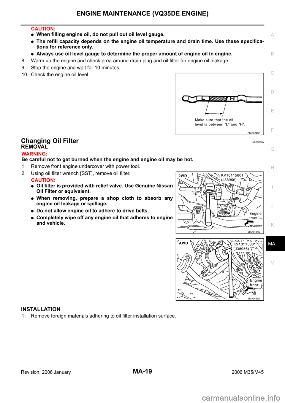
10. Check the engine oil level.
Changing Oil FilterNLS0007N
REMOVAL
WAR NING :
Be careful not to get burned when the engine and engine oil may be hot.
1. Remove front engine undercover with power tool.
2. Using oil filter wrench [SST], remove oil filter.
CAUTION:
Oil filter is provided with relief valve. Use Genuine Nissan
Oil Filter or equivalent.
When removing, prepare a shop cloth to absorb any
engine oil leakage or spillage.
Do not allow engine oil to adhere to drive belts.
Completely wipe off any engine oil that adheres to engine
and vehicle.
INSTALLATION
1. Remove foreign materials adhering to oil filter installation surface.
PBIC0249E
SBIA0454E
SBIA0455E
Page 4803 of 5621

MA-26
ENGINE MAINTENANCE (VK45DE ENGINE)
Revision: 2006 January2006 M35/M45
7. Refill with new engine oil.
Engine oil specification and viscosity:
Refer to MA-12, "
RECOMMENDED FLUIDS AND LUBRICANTS" .
Engine oil capacity (Approximate):
Unit: (US qt, Imp qt)
CAUTION:
The refill capacity depends on the engine oil temperature and drain time. Use these specifica-
tions for reference only.
Always use oil level gauge to determine the proper amount of engine oil in the engine.
8. Warm up engine and check area around drain plug and oil filter for oil leakage.
9. Stop engine and wait for 15 minutes.
10. Check the engine oil level.
Changing Oil FilterNLS0007W
REMOVAL
WAR NING :
Be careful not to get burned when the engine and engine oil may be hot.
1. Remove front engine undercover with power tool.
2. Using the oil filter wrench (SST), remove the oil filter.
CAUTION:
Oil filter is provided with relief valve. Use Genuine Nissan
Oil Filter or equivalent.
When removing, prepare a shop cloth to absorb any
engine oil leakage or spillage.
Do not allow engine oil to adhere to drive belts.
Completely wipe off any engine oil that adhere to engine
and vehicle.
INSTALLATION
1. Remove foreign materials adhering to oil filter installation surface.
2. Apply new engine oil to the oil seal circumference of the new oil
filter.
Drain and refillWith oil filter change 5.5 (5-3/4, 4-7/8)
without oil filter change 4.9 (5-1/8, 4-1/4)
Dry engine (engine overhaul) 6.7 (7-1/8, 5-7/8)
PBIC0801E
PBIC1525E
SMA010
Page 4814 of 5621

CHASSIS AND BODY MAINTENANCE
MA-37
C
D
E
F
G
H
I
J
K
MA
B
MA
Revision: 2006 January2006 M35/M45
Checking Power Steering Fluid and LinesNLS0008E
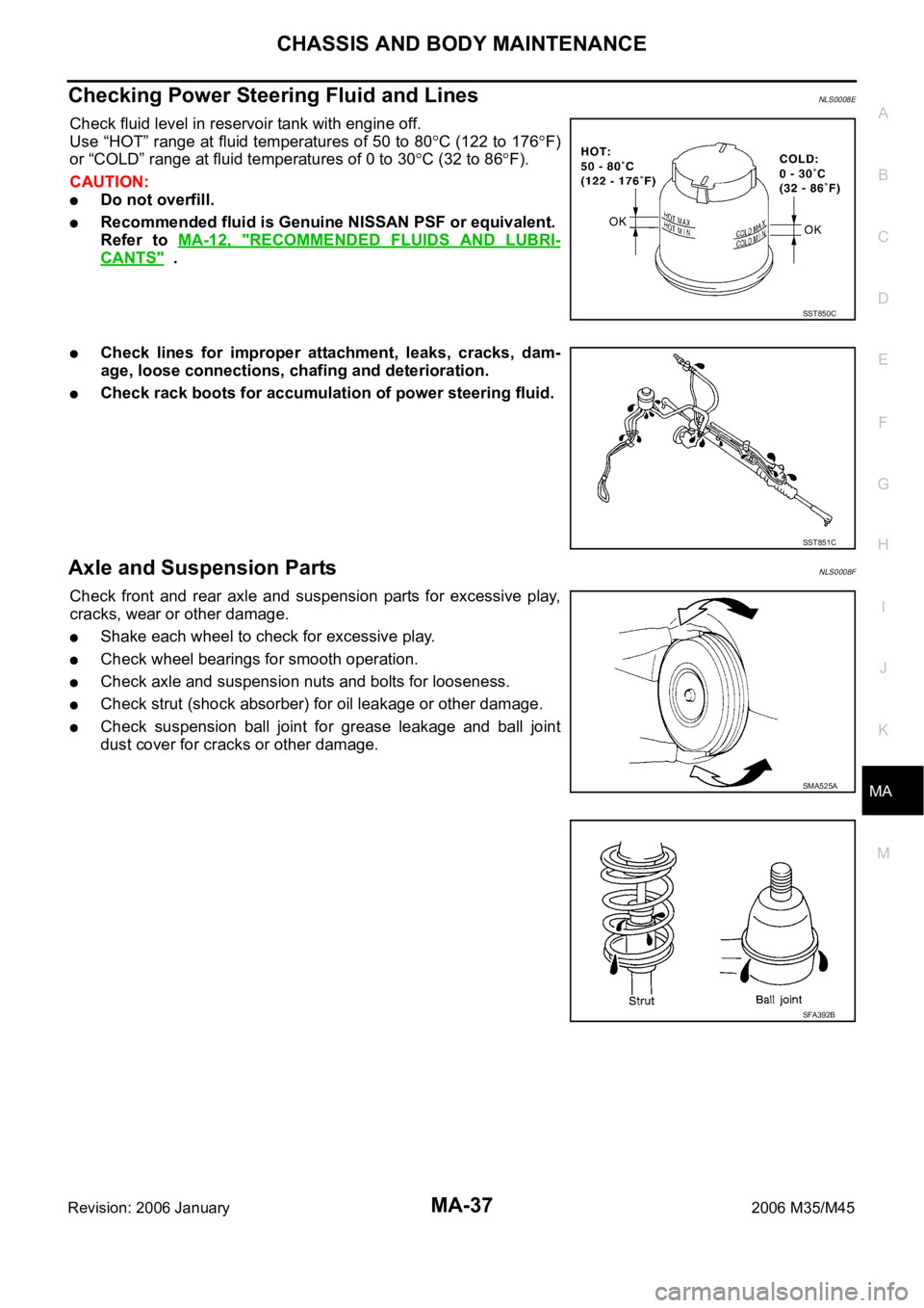
Check fluid level in reservoir tank with engine off.
Use “HOT” range at fluid temperatures of 50 to 80
C (122 to 176F)
or “COLD” range at fluid temperatures of 0 to 30
C (32 to 86F).
CAUTION:
Do not overfill.
Recommended fluid is Genuine NISSAN PSF or equivalent.
Refer to MA-12, "
RECOMMENDED FLUIDS AND LUBRI-
CANTS" .
Check lines for improper attachment, leaks, cracks, dam-
age, loose connections, chafing and deterioration.
Check rack boots for accumulation of power steering fluid.
Axle and Suspension PartsNLS0008F
Check front and rear axle and suspension parts for excessive play,
cracks, wear or other damage.
Shake each wheel to check for excessive play.
Check wheel bearings for smooth operation.
Check axle and suspension nuts and bolts for looseness.
Check strut (shock absorber) for oil leakage or other damage.
Check suspension ball joint for grease leakage and ball joint
dust cover for cracks or other damage.
SST850C
SST851C
SMA525A
SFA392B
Page 5005 of 5621

RAX-6
WHEEL HUB
Revision: 2006 January2006 M35/M45
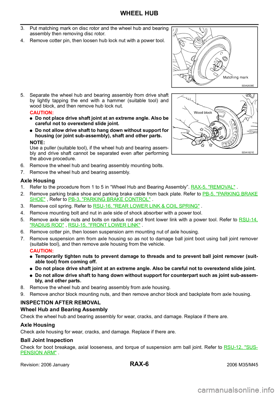
3. Put matching mark on disc rotor and the wheel hub and bearing
assembly then removing disc rotor.
4. Remove cotter pin, then loosen hub lock nut with a power tool.
5. Separate the wheel hub and bearing assembly from drive shaft
by lightly tapping the end with a hammer (suitable tool) and
wood block, and then remove hub lock nut.
CAUTION:
Do not place drive shaft joint at an extreme angle. Also be
careful not to overextend slide joint.
Do not allow drive shaft to hang down without support for
housing (or joint sub-assembly), shaft and other parts.
NOTE:
Use a puller (suitable tool), if the wheel hub and bearing assem-
bly and drive shaft cannot be separated even after performing
the above procedure.
6. Remove the wheel hub and bearing assembly mounting bolts.
7. Remove the wheel hub and bearing assembly.
Axle Housing
1. Refer to the procedure from 1 to 5 in “Wheel Hub and Bearing Assembly”. RAX-5, "REMOVAL" .
2. Remove parking brake shoe and parking brake cable from back plate. Refer to PB-5, "
PA R K I N G B R A K E
SHOE" , Refer to PB-3, "PARKING BRAKE CONTROL" .
3. Remove coil spring. Refer to RSU-16, "
REAR LOWER LINK & COIL SPRING" .
4. Remove mounting bolt and nut in axle side of shock absorber with a power tool.
5. Remove axle side nuts and bolts on radius rod and front lower link with a power tool. Refer to RSU-14,
"RADIUS ROD" , RSU-15, "FRONT LOWER LINK" .
6. Remove cotter pin, then loosen suspension arm mounting nut of axle housing.
7. Remove suspension arm from axle housing so as not to damage ball joint boot using ball joint remover
(suitable tool), and then remove axle housing from the vehicle.
CAUTION:
Temporarily tighten nuts to prevent damage to threads and to prevent ball joint remover (suit-
able tool) from coming off.
Do not place drive shaft joint at an extreme angle. Also be careful not to overextend slide joint.
Do not allow drive shaft to hang down without support for counterpart such as joint sub-assem-
bly, and other parts.
8. Remove the wheel hub and bearing assembly from axle housing.
9. Remove anchor block mounting nuts, and then remove anchor block and backplate from axle housing.
INSPECTION AFTER REMOVAL
Wheel Hub and Bearing Assembly
Check the wheel hub and bearing assembly for wear, cracks, and damage. Replace if there are.
Axle Housing
Check axle housing for wear, cracks, and damage. Replace if there are.
Ball Joint Inspection
Check for boot breakage, axial looseness, and torque of suspension arm ball joint. Refer to RSU-12, "SUS-
PENSION ARM" .
SDIA2638E
SDIA1821E