2006 INFINITI M35 wheel bolts
[x] Cancel search: wheel boltsPage 3460 of 5621
![INFINITI M35 2006 Factory Service Manual UPPER LINK
FSU-33
[AWD]
C
D
F
G
H
I
J
K
L
MA
B
FSU
Revision: 2006 January2006 M35/M45
UPPER LINKPFP:54524
Removal and InstallationNES000IX
REMOVAL
1. Remove tires from vehicle with a power tool.
2. Re INFINITI M35 2006 Factory Service Manual UPPER LINK
FSU-33
[AWD]
C
D
F
G
H
I
J
K
L
MA
B
FSU
Revision: 2006 January2006 M35/M45
UPPER LINKPFP:54524
Removal and InstallationNES000IX
REMOVAL
1. Remove tires from vehicle with a power tool.
2. Re](/manual-img/42/57023/w960_57023-3459.png)
UPPER LINK
FSU-33
[AWD]
C
D
F
G
H
I
J
K
L
MA
B
FSU
Revision: 2006 January2006 M35/M45
UPPER LINKPFP:54524
Removal and InstallationNES000IX
REMOVAL
1. Remove tires from vehicle with a power tool.
2. Remove shock absorber. Refer to FSU-28, "
COIL SPRING AND SHOCK ABSORBER" .
3. Remove mounting nut and bolt with a power tool, and then remove upper link from steering knuckle.
4. Remove mounting nuts and bolts, and then remove upper link and stopper rubber from vehicle.
INSPECTION AFTER REMOVAL
Visual Inspection
Check the following:
Upper link and bushing for deformation, cracks or damage. Replace it if a malfunction is detected.
Ball joint boot for cracks or other damage, and also for grease leakage. Replace it if a malfunction is
detected.
Ball Joint Inspection
Manually move ball stud to confirm it moves smoothly with no binding.
Swing Torque Inspection
NOTE:
Before measurement, move ball stud at least ten times by hand to check for smooth movement.
Hook a spring balance at cutout on ball stud. Confirm spring bal-
ance measurement value is within specifications when ball stud
begins moving.
If it is outside the specified range, replace upper link assembly.
Rotating Torque Inspection
Attach mounting nut to ball stud. Make sure that rotating torque
is within specifications with a preload gauge [SST].
If it is outside the specified range, replace upper link assembly.
Axial End Play Inspection
Move tip of ball stud in axial direction to check for looseness.
If it is outside the specified range, replace upper link assembly.
INSTALLATION
Installation is the reverse order of removal. For tightening torque, refer to FSU-25, "Components" .
Perform final tightening of bolts and nuts at the vehicle installation position (rubber bushing) under
unladen conditions with tires on level ground. Check wheel alignment. Refer to FSU-23, "
Wheel Align-
ment Inspection" . Swing torque
: 0 - 2.0 Nꞏm (0 - 0.2 kg-m, 0 - 17 in-lb)
Spring balance measurement
: 0 - 61.5 N (0 - 6.2 kg, 0 - 13.6 lb)
SEIA0523E
Rotating torque
: 0 - 2.0 Nꞏm (0 - 0.2 kg-m, 0 - 17 in-lb)
SDIA1150E
Axial end play : 0 mm (0 in)
Page 3465 of 5621
GI-2Revision: 2006 January2006 M35/M45 TIGHTENING TORQUE OF STANDARD BOLTS .... 47
Tightening Torque Table ......................................... 47
RECOMMENDED CHEMICAL PRODUCTS AND
SEALANTS ............................................................... 48
Recommended Chemical Products and Sealants ... 48
IDENTIFICATION INFORMATION ............................ 49
Model Variation ....................................................... 49
IDENTIFICATION NUMBER ................................ 50IDENTIFICATION PLATE .................................... 51
ENGINE SERIAL NUMBER ................................. 51
AUTOMATIC TRANSMISSION NUMBER ........... 51
Dimensions ............................................................. 52
Wheels & Tires ........................................................ 52
TERMINOLOGY ........................................................ 53
SAE J1930 Terminology List ................................... 53
Page 4814 of 5621
CHASSIS AND BODY MAINTENANCE
MA-37
C
D
E
F
G
H
I
J
K
MA
B
MA
Revision: 2006 January2006 M35/M45
Checking Power Steering Fluid and LinesNLS0008E
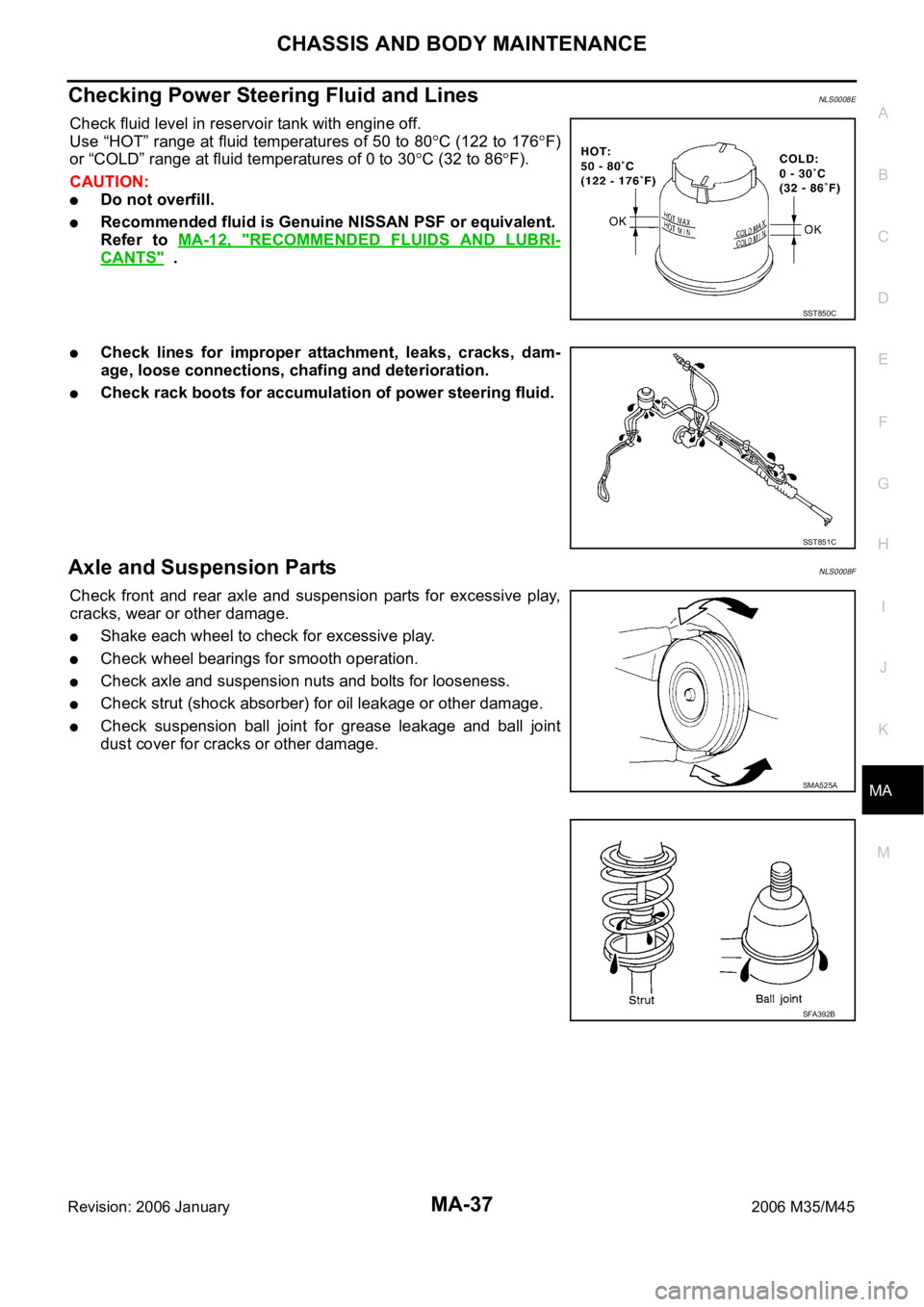
Check fluid level in reservoir tank with engine off.
Use “HOT” range at fluid temperatures of 50 to 80
C (122 to 176F)
or “COLD” range at fluid temperatures of 0 to 30
C (32 to 86F).
CAUTION:
Do not overfill.
Recommended fluid is Genuine NISSAN PSF or equivalent.
Refer to MA-12, "
RECOMMENDED FLUIDS AND LUBRI-
CANTS" .
Check lines for improper attachment, leaks, cracks, dam-
age, loose connections, chafing and deterioration.
Check rack boots for accumulation of power steering fluid.
Axle and Suspension PartsNLS0008F
Check front and rear axle and suspension parts for excessive play,
cracks, wear or other damage.
Shake each wheel to check for excessive play.
Check wheel bearings for smooth operation.
Check axle and suspension nuts and bolts for looseness.
Check strut (shock absorber) for oil leakage or other damage.
Check suspension ball joint for grease leakage and ball joint
dust cover for cracks or other damage.
SST850C
SST851C
SMA525A
SFA392B
Page 4963 of 5621
PS-10
STEERING WHEEL
Revision: 2006 January2006 M35/M45
STEERING WHEELPFP:48430
On-Vehicle Inspection and ServiceNGS000D8
CHECKING CONDITION OF INSTALLATION
Check installation conditions of steering gear assembly, front suspension assembly, axle and steering col-
umn assembly.
Check if movement exists when steering wheel is moved up and down, to the left and right and to the axial
direction.
Check steering gear assembly mounting bolts and nut for looseness. Refer to PS-18, "COMPONENTS" .
CHECKING STEERING WHEEL PLAY
Turn steering wheel so that front wheels come to the straight-ahead position. Start engine and lightly turn
steering wheel to the left and right until front wheels start to move. Measure steering wheel movement on
the outer circumference.
When the measurement value is outside the standard value, check backlash for each joint of steering col-
umn assembly and installation condition of steering gear assembly.
CHECKING NEUTRAL POSITION STEERING WHEEL
Make sure that steering gear assembly, steering column assembly and steering wheel are installed in the
correct position.
Perform neutral position inspection after wheel alignment. Refer to FSU-6, "Wheel Alignment Inspection"
(2WD), FSU-23, "Wheel Alignment Inspection" (AWD).
Set vehicle to the straight-ahead position and confirm steering wheel is in the neutral position.
Loosen outer socket lock nut and turn inner socket to left and right equally to make fine adjustments if
steering wheel is not in the neutral position.
CHECKING STEERING WHEEL TURNING FORCE
1. Park vehicle on a level and dry surface, set parking brake.
2. Start engine.
3. Bring power steering fluid up to adequate operating temperature. [Make sure temperature of fluid is
approximately 50 to 80
C (122 to 176F).]
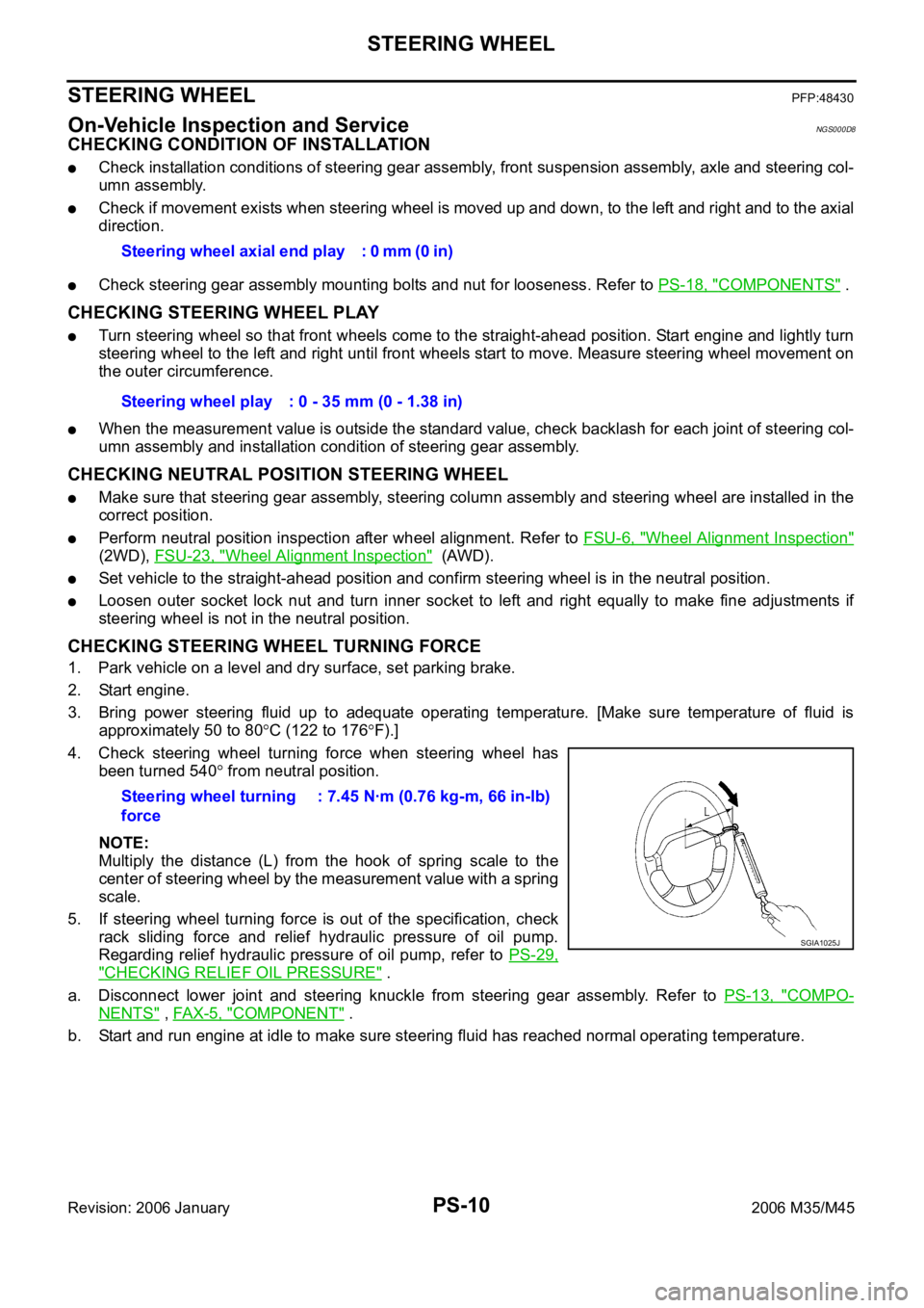
4. Check steering wheel turning force when steering wheel has
been turned 540
from neutral position.
NOTE:
Multiply the distance (L) from the hook of spring scale to the
center of steering wheel by the measurement value with a spring
scale.
5. If steering wheel turning force is out of the specification, check
rack sliding force and relief hydraulic pressure of oil pump.
Regarding relief hydraulic pressure of oil pump, refer to PS-29,
"CHECKING RELIEF OIL PRESSURE" .
a. Disconnect lower joint and steering knuckle from steering gear assembly. Refer to PS-13, "
COMPO-
NENTS" , FAX-5, "COMPONENT" .
b. Start and run engine at idle to make sure steering fluid has reached normal operating temperature. Steering wheel axial end play : 0 mm (0 in)
Steering wheel play : 0 - 35 mm (0 - 1.38 in)
Steering wheel turning
force: 7.45 Nꞏm (0.76 kg-m, 66 in-lb)
SGIA1025J
Page 4968 of 5621
STEERING COLUMN
PS-15
C
D
E
F
H
I
J
K
L
MA
B
PS
Revision: 2006 January2006 M35/M45
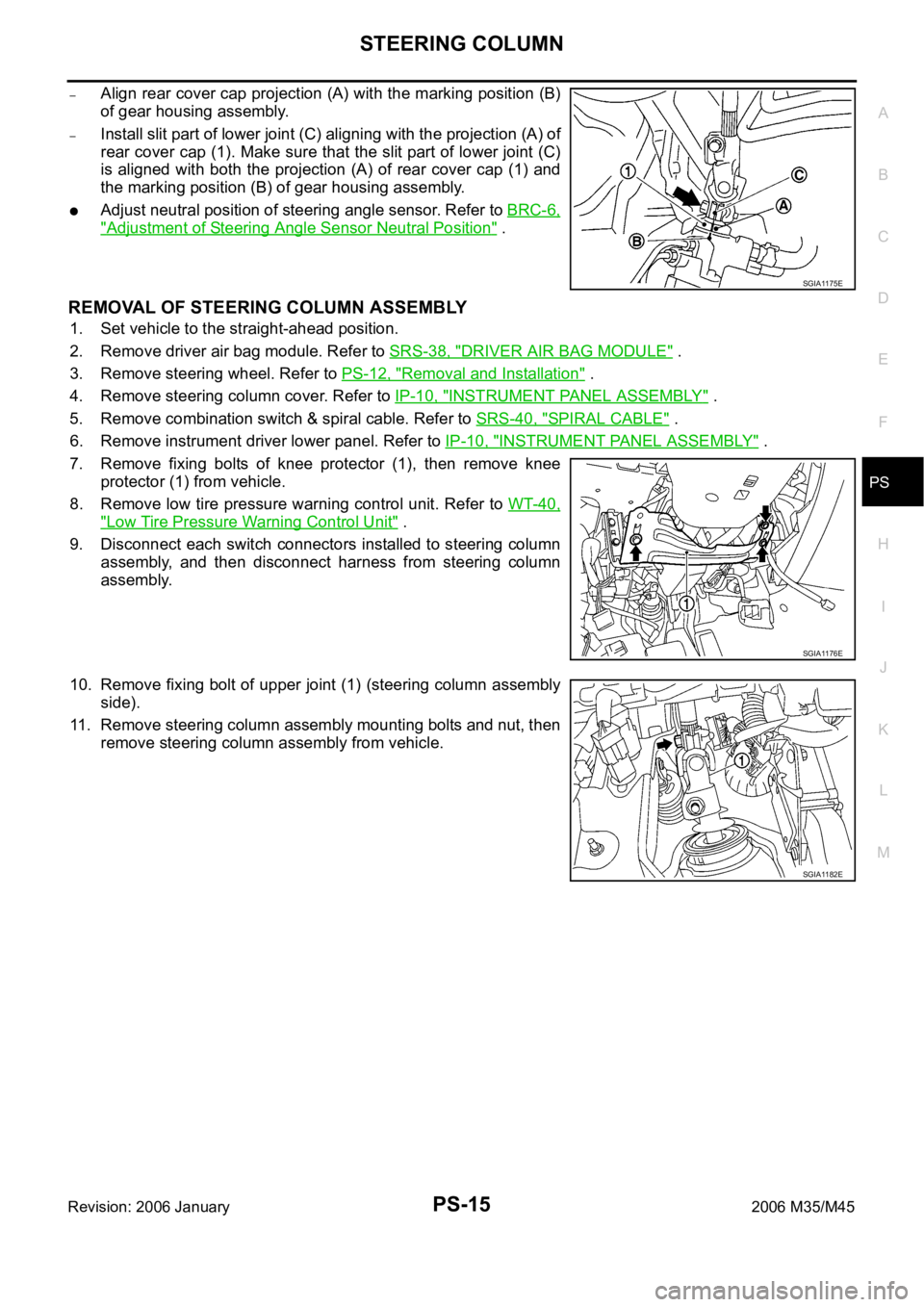
–Align rear cover cap projection (A) with the marking position (B)
of gear housing assembly.
–Install slit part of lower joint (C) aligning with the projection (A) of
rear cover cap (1). Make sure that the slit part of lower joint (C)
is aligned with both the projection (A) of rear cover cap (1) and
the marking position (B) of gear housing assembly.
Adjust neutral position of steering angle sensor. Refer to BRC-6,
"Adjustment of Steering Angle Sensor Neutral Position" .
REMOVAL OF STEERING COLUMN ASSEMBLY
1. Set vehicle to the straight-ahead position.
2. Remove driver air bag module. Refer to SRS-38, "
DRIVER AIR BAG MODULE" .
3. Remove steering wheel. Refer to PS-12, "
Removal and Installation" .
4. Remove steering column cover. Refer to IP-10, "
INSTRUMENT PANEL ASSEMBLY" .
5. Remove combination switch & spiral cable. Refer to SRS-40, "
SPIRAL CABLE" .
6. Remove instrument driver lower panel. Refer to IP-10, "
INSTRUMENT PANEL ASSEMBLY" .
7. Remove fixing bolts of knee protector (1), then remove knee
protector (1) from vehicle.
8. Remove low tire pressure warning control unit. Refer to WT-40,
"Low Tire Pressure Warning Control Unit" .
9. Disconnect each switch connectors installed to steering column
assembly, and then disconnect harness from steering column
assembly.
10. Remove fixing bolt of upper joint (1) (steering column assembly
side).
11. Remove steering column assembly mounting bolts and nut, then
remove steering column assembly from vehicle.
SGIA1175E
SGIA1176E
SGIA1182E
Page 4972 of 5621
POWER STEERING GEAR
PS-19
C
D
E
F
H
I
J
K
L
MA
B
PS
Revision: 2006 January2006 M35/M45
8. Remove steering hydraulic piping bracket from front suspension member. Refer to PS-38, "HYDRAULIC
LINE" .
9. Remove EPS solenoid valve harness connector. Refer to PS-20, "
COMPONENTS" .
10. Remove rack stay (2WD) or front cross bar (AWD). Refer to FSU-8, "
Components" , FSU-25, "Compo-
nents" .
11. Remove mounting bolts and nuts of steering gear assembly, and then remove steering gear assembly
from vehicle.
INSTALLATION
Installation is the reverse order of removal. For tightening torque, refer to PS-18, "COMPONENTS" .
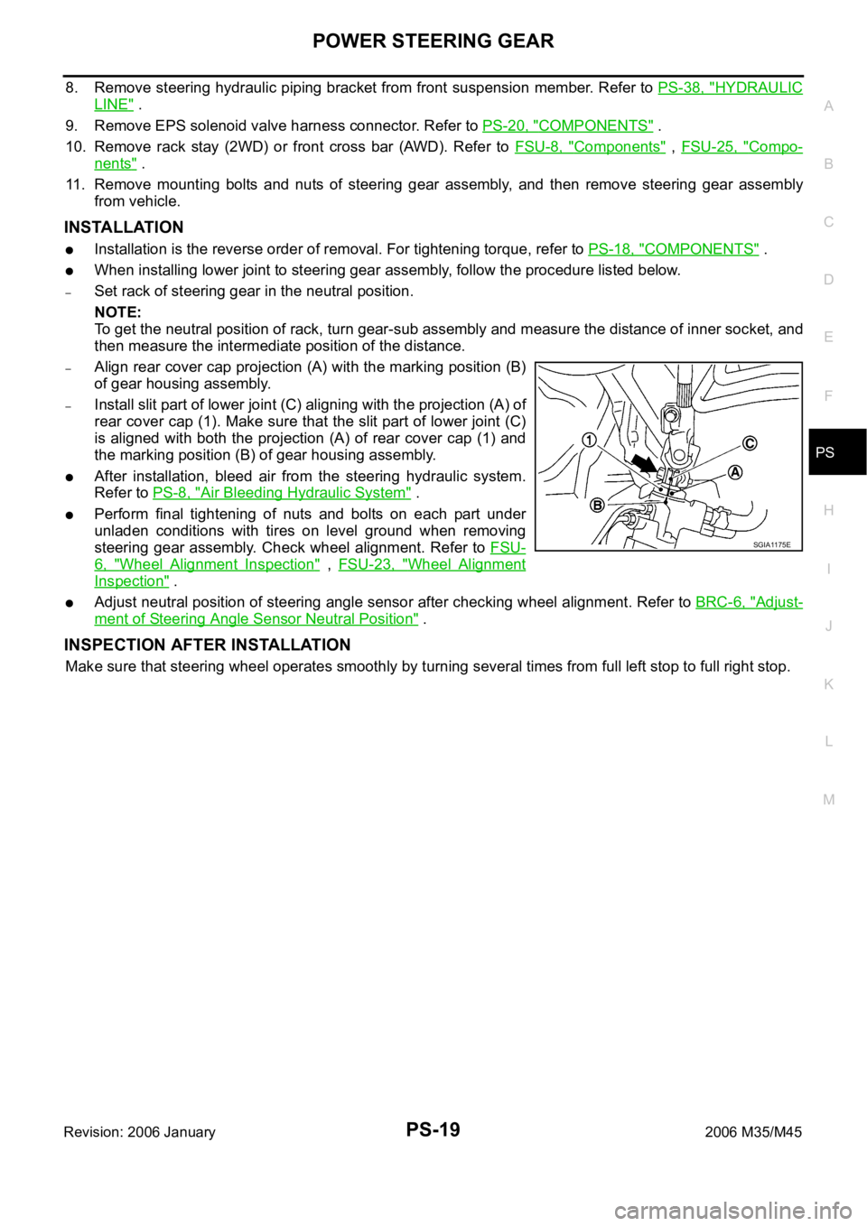
When installing lower joint to steering gear assembly, follow the procedure listed below.
–Set rack of steering gear in the neutral position.
NOTE:
To get the neutral position of rack, turn gear-sub assembly and measure the distance of inner socket, and
then measure the intermediate position of the distance.
–Align rear cover cap projection (A) with the marking position (B)
of gear housing assembly.
–Install slit part of lower joint (C) aligning with the projection (A) of
rear cover cap (1). Make sure that the slit part of lower joint (C)
is aligned with both the projection (A) of rear cover cap (1) and
the marking position (B) of gear housing assembly.
After installation, bleed air from the steering hydraulic system.
Refer to PS-8, "
Air Bleeding Hydraulic System" .
Perform final tightening of nuts and bolts on each part under
unladen conditions with tires on level ground when removing
steering gear assembly. Check wheel alignment. Refer to FSU-
6, "Wheel Alignment Inspection" , FSU-23, "Wheel Alignment
Inspection" .
Adjust neutral position of steering angle sensor after checking wheel alignment. Refer to BRC-6, "Adjust-
ment of Steering Angle Sensor Neutral Position" .
INSPECTION AFTER INSTALLATION
Make sure that steering wheel operates smoothly by turning several times from full left stop to full right stop.
SGIA1175E
Page 5005 of 5621
RAX-6
WHEEL HUB
Revision: 2006 January2006 M35/M45
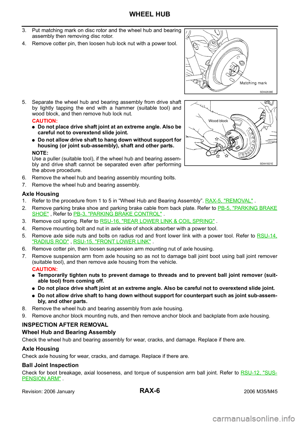
3. Put matching mark on disc rotor and the wheel hub and bearing
assembly then removing disc rotor.
4. Remove cotter pin, then loosen hub lock nut with a power tool.
5. Separate the wheel hub and bearing assembly from drive shaft
by lightly tapping the end with a hammer (suitable tool) and
wood block, and then remove hub lock nut.
CAUTION:
Do not place drive shaft joint at an extreme angle. Also be
careful not to overextend slide joint.
Do not allow drive shaft to hang down without support for
housing (or joint sub-assembly), shaft and other parts.
NOTE:
Use a puller (suitable tool), if the wheel hub and bearing assem-
bly and drive shaft cannot be separated even after performing
the above procedure.
6. Remove the wheel hub and bearing assembly mounting bolts.
7. Remove the wheel hub and bearing assembly.
Axle Housing
1. Refer to the procedure from 1 to 5 in “Wheel Hub and Bearing Assembly”. RAX-5, "REMOVAL" .
2. Remove parking brake shoe and parking brake cable from back plate. Refer to PB-5, "
PA R K I N G B R A K E
SHOE" , Refer to PB-3, "PARKING BRAKE CONTROL" .
3. Remove coil spring. Refer to RSU-16, "
REAR LOWER LINK & COIL SPRING" .
4. Remove mounting bolt and nut in axle side of shock absorber with a power tool.
5. Remove axle side nuts and bolts on radius rod and front lower link with a power tool. Refer to RSU-14,
"RADIUS ROD" , RSU-15, "FRONT LOWER LINK" .
6. Remove cotter pin, then loosen suspension arm mounting nut of axle housing.
7. Remove suspension arm from axle housing so as not to damage ball joint boot using ball joint remover
(suitable tool), and then remove axle housing from the vehicle.
CAUTION:
Temporarily tighten nuts to prevent damage to threads and to prevent ball joint remover (suit-
able tool) from coming off.
Do not place drive shaft joint at an extreme angle. Also be careful not to overextend slide joint.
Do not allow drive shaft to hang down without support for counterpart such as joint sub-assem-
bly, and other parts.
8. Remove the wheel hub and bearing assembly from axle housing.
9. Remove anchor block mounting nuts, and then remove anchor block and backplate from axle housing.
INSPECTION AFTER REMOVAL
Wheel Hub and Bearing Assembly
Check the wheel hub and bearing assembly for wear, cracks, and damage. Replace if there are.
Axle Housing
Check axle housing for wear, cracks, and damage. Replace if there are.
Ball Joint Inspection
Check for boot breakage, axial looseness, and torque of suspension arm ball joint. Refer to RSU-12, "SUS-
PENSION ARM" .
SDIA2638E
SDIA1821E
Page 5006 of 5621
WHEEL HUB
RAX-7
C
E
F
G
H
I
J
K
L
MA
B
RAX
Revision: 2006 January2006 M35/M45
INSTALLATION
Wheel Hub and Bearing Assembly
Installation is the reverse order of removal. For tightening torque refer to RAX-5, "COMPONENT" .
CAUTION:
Do not reuse non-reusable parts.
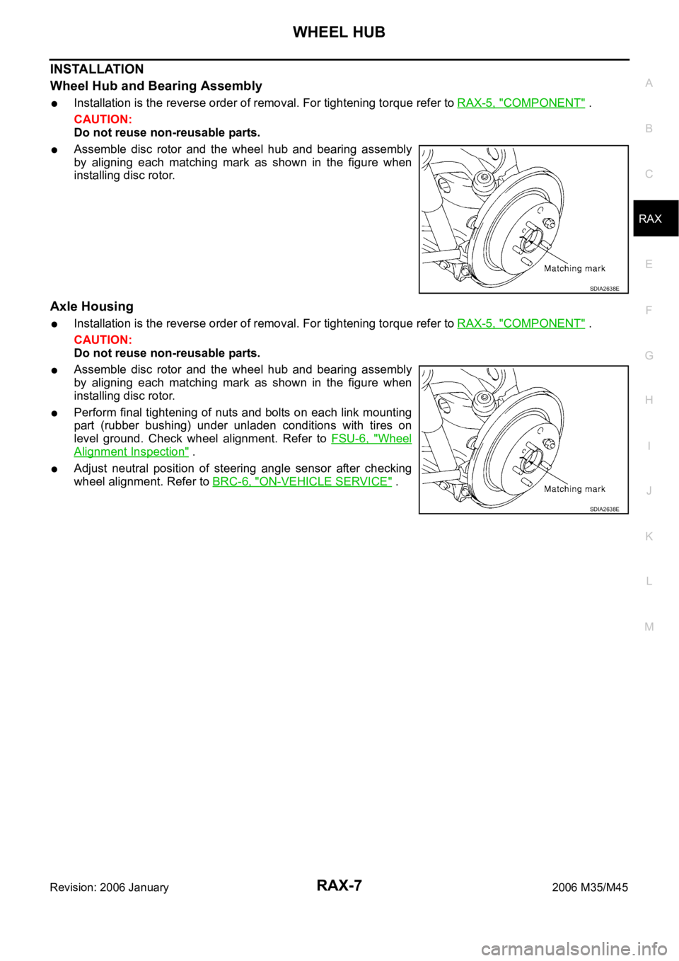
Assemble disc rotor and the wheel hub and bearing assembly
by aligning each matching mark as shown in the figure when
installing disc rotor.
Axle Housing
Installation is the reverse order of removal. For tightening torque refer to RAX-5, "COMPONENT" .
CAUTION:
Do not reuse non-reusable parts.
Assemble disc rotor and the wheel hub and bearing assembly
by aligning each matching mark as shown in the figure when
installing disc rotor.
Perform final tightening of nuts and bolts on each link mounting
part (rubber bushing) under unladen conditions with tires on
level ground. Check wheel alignment. Refer to FSU-6, "
Wheel
Alignment Inspection" .
Adjust neutral position of steering angle sensor after checking
wheel alignment. Refer to BRC-6, "
ON-VEHICLE SERVICE" .
SDIA2638E
SDIA2638E