2006 INFINITI M35 lock
[x] Cancel search: lockPage 1426 of 5621
![INFINITI M35 2006 Factory Service Manual COOLING FAN
CO-51
[VK45DE]
C
D
E
F
G
H
I
J
K
L
MA
CO
Revision: 2006 January2006 M35/M45
COOLING FANPFP:21140
ComponentsNBS004RM
Removal and InstallationNBS004RN
REMOVAL
1. Remove engine room cover (RH INFINITI M35 2006 Factory Service Manual COOLING FAN
CO-51
[VK45DE]
C
D
E
F
G
H
I
J
K
L
MA
CO
Revision: 2006 January2006 M35/M45
COOLING FANPFP:21140
ComponentsNBS004RM
Removal and InstallationNBS004RN
REMOVAL
1. Remove engine room cover (RH](/manual-img/42/57023/w960_57023-1425.png)
COOLING FAN
CO-51
[VK45DE]
C
D
E
F
G
H
I
J
K
L
MA
CO
Revision: 2006 January2006 M35/M45
COOLING FANPFP:21140
ComponentsNBS004RM
Removal and InstallationNBS004RN
REMOVAL
1. Remove engine room cover (RH and LH). Refer to EM-173, "ENGINE ROOM COVER" .
2. Remove air duct (inlet) and air cleaner case assembly. Refer to EM-177, "
AIR CLEANER AND AIR
DUCT" .
3. Drain engine coolant from radiator. Refer to CO-40, "
ENGINE COOLANT" .
4. Disconnect harness connector from cooling fan control module, and move harness to aside.
5. Remove radiator hose (upper). Refer to CO-43, "
RADIATOR" .
6. Remove cooling fan assembly.
CAUTION:
Be careful not to damage or scratch on radiator core.
INSTALLATION
Note the following, and Install in the reverse order of removal.
CAUTION:
Only use genuine parts for radiator shroud and cooling fan mounting bolt and observe the specified
torque (to prevent radiator from being damaged).
INSPECTION AFTER INSTALLATION
Make sure that fan motors operate normally.
1. Sub-harness 2. Cooling fan control module 3. Sub-harness
4. Fan motor (LH) 5. Fan motor (RH) 6. Fan shroud
7. Cooling fan (RH) 8. Cooling fan (LH)
A. Apply on fan motor shaft.
Apply Genuine High Strength Lock-
ing Sealant or equivalent.
KBIA3567J
Page 1428 of 5621
![INFINITI M35 2006 Factory Service Manual WATER PUMP
CO-53
[VK45DE]
C
D
E
F
G
H
I
J
K
L
MA
CO
Revision: 2006 January2006 M35/M45
WAT E R PU M PPFP:21020
ComponentsNBS004RP
Refer to GI-11, "Components" for symbol marks in the figure. INFINITI M35 2006 Factory Service Manual WATER PUMP
CO-53
[VK45DE]
C
D
E
F
G
H
I
J
K
L
MA
CO
Revision: 2006 January2006 M35/M45
WAT E R PU M PPFP:21020
ComponentsNBS004RP
Refer to GI-11, "Components" for symbol marks in the figure.](/manual-img/42/57023/w960_57023-1427.png)
WATER PUMP
CO-53
[VK45DE]
C
D
E
F
G
H
I
J
K
L
MA
CO
Revision: 2006 January2006 M35/M45
WAT E R PU M PPFP:21020
ComponentsNBS004RP
Refer to GI-11, "Components" for symbol marks in the figure.
Removal and InstallationNBS004RQ
CAUTION:
When removing water pump, be careful not to get engine coolant on drive belts.
Water pump can not be disassembled and should be replaced as a unit.
After installing water pump, connect hose and clamp securely, then check for leaks using radiator
cap tester (commercial service tool) and radiator cap tester adapter [SST: EG17650301 (J33984-
A)].
REMOVAL
1. Remove following parts:
Front engine undercover (power tool)
Engine cover: Refer to EM-179, "INTAKE MANIFOLD" .
Engine room cover (RH and LH): Refer to EM-173, "ENGINE ROOM COVER" .
Air duct (inlet): Refer to EM-177, "AIR CLEANER AND AIR DUCT" .
Alternator, water pump and A/C compressor belt: Refer to EM-174, "DRIVE BELTS" .
2. Drain engine coolant from drain plugs on radiator and both side of cylinder block. Refer to CO-40, "
Chang-
ing Engine Coolant" and EM-250, "DISASSEMBLY" .
CAUTION:
Perform this step when engine is cold.
Do not spill engine coolant on drive belts.
3. Remove water pump pulley.
4. Remove water pump.
Engine coolant will leak from cylinder block, so have a receptacle ready under vehicle.
CAUTION:
Handle the water pump vane so that it does not contact any other parts.
Do not disassemble water pump.
1. Water pump 2. Water pump pulley 3. Gasket
PBIC3396E
Page 1430 of 5621
![INFINITI M35 2006 Factory Service Manual THERMOSTAT AND WATER CONTROL VALVE
CO-55
[VK45DE]
C
D
E
F
G
H
I
J
K
L
MA
CO
Revision: 2006 January2006 M35/M45
THERMOSTAT AND WATER CONTROL VALVEPFP:21200
ComponentsNBS004RR
Refer to GI-11, "Compo INFINITI M35 2006 Factory Service Manual THERMOSTAT AND WATER CONTROL VALVE
CO-55
[VK45DE]
C
D
E
F
G
H
I
J
K
L
MA
CO
Revision: 2006 January2006 M35/M45
THERMOSTAT AND WATER CONTROL VALVEPFP:21200
ComponentsNBS004RR
Refer to GI-11, "Compo](/manual-img/42/57023/w960_57023-1429.png)
THERMOSTAT AND WATER CONTROL VALVE
CO-55
[VK45DE]
C
D
E
F
G
H
I
J
K
L
MA
CO
Revision: 2006 January2006 M35/M45
THERMOSTAT AND WATER CONTROL VALVEPFP:21200
ComponentsNBS004RR
Refer to GI-11, "Components" for symbol marks in the figure.
Removal and InstallationNBS004RS
REMOVAL
1. Remove engine room cover (RH and LH). Refer to EM-173, "ENGINE ROOM COVER" .
2. Remove engine cover with power tool. Refer to EM-179, "
INTAKE MANIFOLD" .
3. Remove air duct (inlet). Refer to EM-177, "
AIR CLEANER AND AIR DUCT" .
4. Drain engine coolant from drain plugs on radiator and both side of cylinder block. Refer to CO-40, "
Chang-
ing Engine Coolant" and EM-250, "DISASSEMBLY" .
CAUTION:
Perform this step when engine is cold.
Do not spill engine coolant on drive belts.
1. Water connector 2. O-ring 3. Rubber ring
4. Heater hose 5. Water control valve 6. Water outlet
7. Gasket 8. O-ring 9. Water outlet pipe
10. Thermostat housing 11. Radiator cap 12. Radiator hose (upper)
13. Thermostat 14. Rubber ring 15. Water inlet
16. Water suction hose 17. Water suction pipe 18. Radiator hose (lower)
19. Gasket 20. O-ring 21. Heater pipe
22. Heater hose
A. To radiator B. To intake manifold adapter C. To cylinder block
D. To cylinder head (right bank) E. To cylinder head (left bank) F.To heater core
PBIC3306E
Page 1435 of 5621

DI-2Revision: 2006 January2006 M35/M45 A/T INDICATOR ........................................................ 56
System Description ................................................. 56
MANUAL MODE .................................................. 56
NOT MANUAL MODE ......................................... 56
Wiring Diagram — AT/IND — ................................. 57
A/T Indicator Is Malfunction .................................... 59
WARNING CHIME .................................................. ... 60
System Description ................................................. 60
POWER SUPPLY AND GROUND CIRCUIT ....... 60
IGNITION KEY WARNING CHIME (WITH INTEL-
LIGENT KEY) ...................................................... 61
LIGHT WARNING CHIME ................................... 61
SEAT BELT WARNING CHIME ........................... 61
Component Parts and Harness Connector Location ... 62
Schematic ............................................................... 63
Wiring Diagram — CHIME — ................................. 64
Terminals and Reference Value for Combination
Meter ...................................................................... 67
Terminals and Reference Value for Unified Meter
and A/C Amp. ......................................................... 67
Terminals and Reference Value for BCM ................ 68
CONSULT-II Function (BCM) .................................. 69
CONSULT-II BASIC OPERATION ....................... 69
DATA MONITOR .................................................. 70
ACTIVE TEST ..................................................... 71
SELF-DIAG RESULTS ........................................ 71
CONSULT-II Function (METER A/C AMP) ............. 71
Trouble Diagnosis ................................................... 71
HOW TO PERFORM TROUBLE DIAGNOSIS .... 71
PRELIMINARY INSPECTION ............................. 71
SYMPTOM CHART ............................................. 72
Meter Buzzer Circuit Inspection .............................. 72
Lighting Switch Signal Inspection ........................... 73
Front Door Switch (Driver Side) Signal Inspection ... 73
Seat Belt Buckle Switch Signal Inspection ............. 74
Electrical Component Inspection ............................ 76
FRONT DOOR SWITCH (DRIVER SIDE) ........... 76
SEAT BELT BUCKLE SWITCH (DRIVER SIDE) ... 76
CAN COMMUNICATION ........................................... 77
System Description ................................................. 77
CAN Communication Unit ....................................... 77
LANE DEPARTURE WARNING SYSTEM ................ 78
Precautions for Lane Departure Warning (LDW)
system .................................................................... 78
System Description ................................................. 78
LDW SYSTEM OPERATION ............................... 78
POWER SUPPLY AND GROUND CIRCUIT ....... 80
Action Test ...........................................................
... 80
LDW SYSTEM RUNNING TEST ......................... 80
Camera Aiming Adjustment .................................... 81
OUTLINE ............................................................. 81
PREPARATION ................................................... 81TARGET SETTING .............................................. 81
VEHICLE HEIGHT CHECK ................................. 84
AIMING ADJUSTMENT ....................................... 84
Component Parts and Harness Connector Location ... 88
Wiring Diagram — LDW — ..................................... 89
Terminals and Reference Value for LDW Camera
Unit .......................................................................... 91
CONSULT-II Function (LDW) .................................. 91
DESCRIPTION .................................................... 91
CONSULT-II BASIC OPERATION ....................... 91
WORK SUPPORT ............................................... 92
SELF-DIAG RESULTS ......................................... 92
DATA MONITOR .................................................. 93
ACTIVE TEST ...................................................... 94
Trouble Diagnosis ................................................... 95
HOW TO PERFORM TROUBLE DIAGNOSIS .... 95
PRELIMINARY INSPECTION .............................. 95
SYMPTOM CHART .............................................. 96
Power Supply and Ground Circuit Inspection ......... 96
DTC [C1B00] CAMERA UNIT MALF ...................... 97
DTC [C1B01] CAM AIMING INCMP ....................... 97
DTC [C1B02] VHCL SPD DATA MALF ................... 97
DTC [C1B03] ABNRML TEMP DETECT ................ 97
DTC [U1000] CAN COMM CIRCUIT ...................... 98
DTC [U1010] CONTROL UNIT (CAN) .................... 98
LDW Chime Circuit Inspection ................................ 98
LDW Switch Circuit Inspection ................................ 99
LDW Indicator Lamp Circuit Inspection .................102
Turn Signal Input Inspection .................................103
Electrical Component Inspection ..........................103
LDW SWITCH ....................................................103
Removal and Installation for LDW Camera Unit ...103
REMOVAL ..........................................................103
INSTALLATION ..................................................103
Removal and Installation for LDW Chime .............104
REMOVAL ..........................................................104
INSTALLATION ..................................................104
Removal and Installation for LDW Switch .............104
COMPASS ...............................................................105
System Description ...............................................105
DIRECTION DISPLAY .......................................105
Zone Variation Change Procedure ........................105
Correction Functions of the Compass Display ......105
AUTOMATIC CORRECTION .............................105
MANUAL CORRECTION PROCEDURE ...........105
Wiring Diagram – COMPAS – ...............................106
Removal and Installation of Compass ...................107
CLOCK ....................................................................108
Wiring Diagram — CLOCK — ...............................108
Removal and Installation of Clock .........................109
REMOVAL ..........................................................109
INSTALLATION ..................................................109
Page 1438 of 5621

COMBINATION METERS
DI-5
C
D
E
F
G
H
I
J
L
MA
B
DI
Revision: 2006 January2006 M35/M45
COMBINATION METERSPFP:24814
System DescriptionNKS003TV
UNIFIED METER CONTROL UNIT
Speedometer, odo/trip meter, tachometer, fuel gauge and water temperature gauge are controlled by the
unified meter control unit, which is built into the combination meter. Unified meter control unit receives sig-
nals from unified meter and A/C amp.
Warning lamp and indicator lamp of combination meter are controlled by signals drawn from the unified
meter and A/C amp.
Digital meter is adopted for odo/trip meter.
NOTE:
The record of the odo meter is kept even if the battery cable is disconnected. The record of the trip meter
is erased when the battery cable is disconnected.
Dot matrix LCD is adopted to display “push engine starter”, “A/T position” and “ICC system* ”.
Odo/trip meter and dot matrix LCD segments can be checked in self-diagnosis mode.
Meters/gauges can be checked in self-diagnosis mode.
*: With ICC system
UNIFIED METER AND A/C AMP.
Refer to DI-28, "COMBINATION METER CONTROL FUNCTION" in “UNIFIED METER AND A/C AMP”.
POWER SUPPLY AND GROUND CIRCUIT
Power is supplied at all times
through 10A fuse [No. 21, located in the fuse block (J/B)]
to combination meter terminal 23,
through 10A fuse [No. 19, located in the fuse block (J/B)]
to unified meter and A/C amp. terminal 54.
With the ignition switch in the ACC or ON position, power is supplied
through 10A fuse [No. 6, located in the fuse block (J/B)],
to combination meter terminal 2, and
to unified meter and A/C amp. terminal 41.
With the ignition switch in the ON or START position, power is supplied
through 10A fuse [No. 14, located in the fuse block (J/B)]
to combination meter terminal 12,
through 10A fuse [No. 12, located in the fuse block (J/B)]
to unified meter and A/C amp. terminal 53.
Ground is supplied
to combination meter terminals 9, 10 and 11
to unified meter and A/C amp. terminals 55 and 71
through grounds M16 and M70.
Page 1465 of 5621

DI-32
UNIFIED METER AND A/C AMP
Revision: 2006 January2006 M35/M45
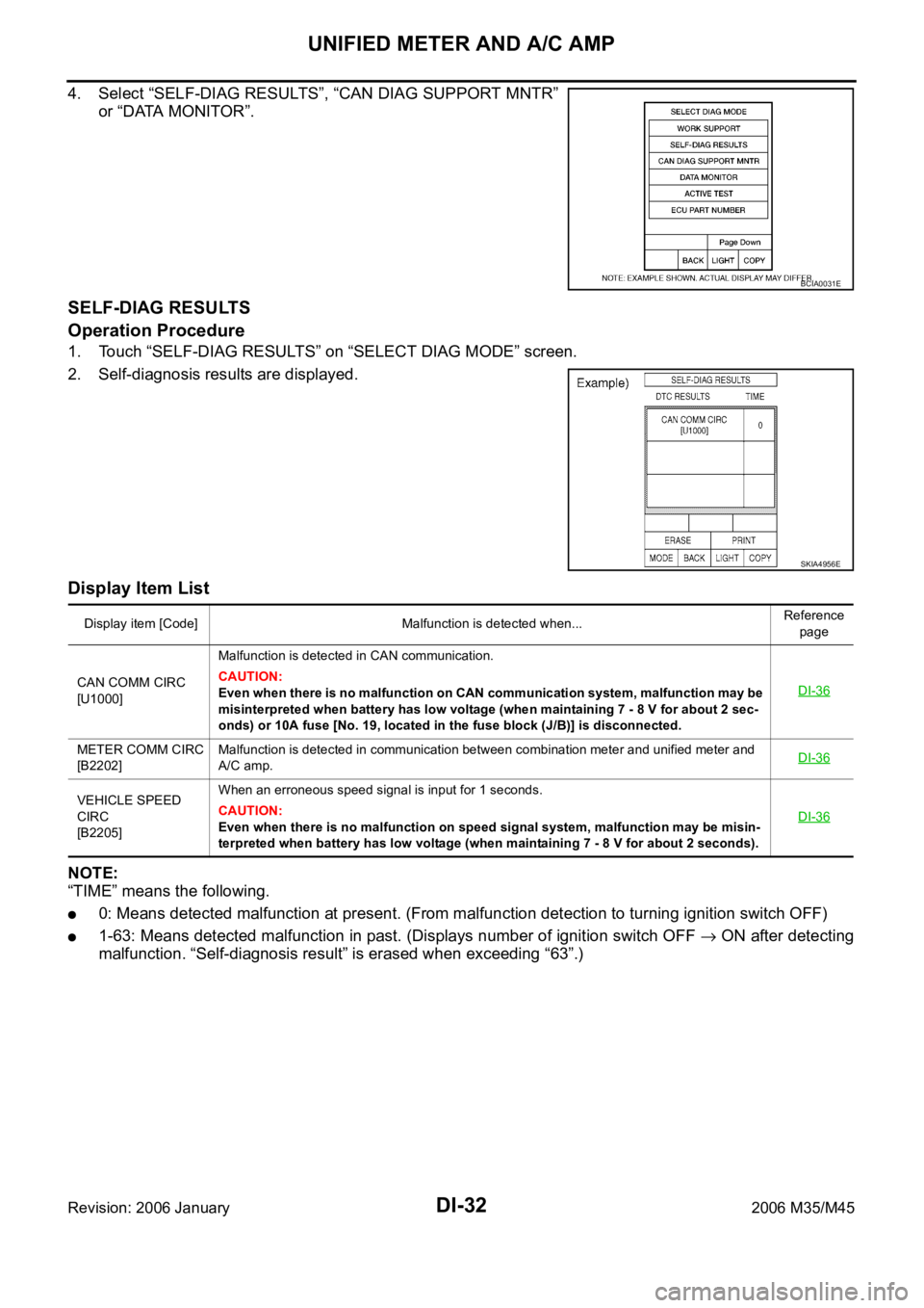
4. Select “SELF-DIAG RESULTS”, “CAN DIAG SUPPORT MNTR”
or “DATA MONITOR”.
SELF-DIAG RESULTS
Operation Procedure
1. Touch “SELF-DIAG RESULTS” on “SELECT DIAG MODE” screen.
2. Self-diagnosis results are displayed.
Display Item List
NOTE:
“TIME” means the following.
0: Means detected malfunction at present. (From malfunction detection to turning ignition switch OFF)
1-63: Means detected malfunction in past. (Displays number of ignition switch OFF ON after detecting
malfunction. “Self-diagnosis result” is erased when exceeding “63”.)
BCIA0031E
SKIA4956E
Display item [Code] Malfunction is detected when...Reference
page
CAN COMM CIRC
[U1000]Malfunction is detected in CAN communication.
CAUTION:
Even when there is no malfunction on CAN communication system, malfunction may be
misinterpreted when battery has low voltage (when maintaining 7 - 8 V for about 2 sec-
onds) or 10A fuse [No. 19, located in the fuse block (J/B)] is disconnected.DI-36
METER COMM CIRC
[B2202]Malfunction is detected in communication between combination meter and unified meter and
A/C amp.DI-36
VEHICLE SPEED
CIRC
[B2205]When an erroneous speed signal is input for 1 seconds.
CAUTION:
Even when there is no malfunction on speed signal system, malfunction may be misin-
terpreted when battery has low voltage (when maintaining 7 - 8 V for about 2 seconds). DI-36
Page 1493 of 5621

DI-60
WARNING CHIME
Revision: 2006 January2006 M35/M45
WARNING CHIMEPFP:24814
System DescriptionNKS003UY
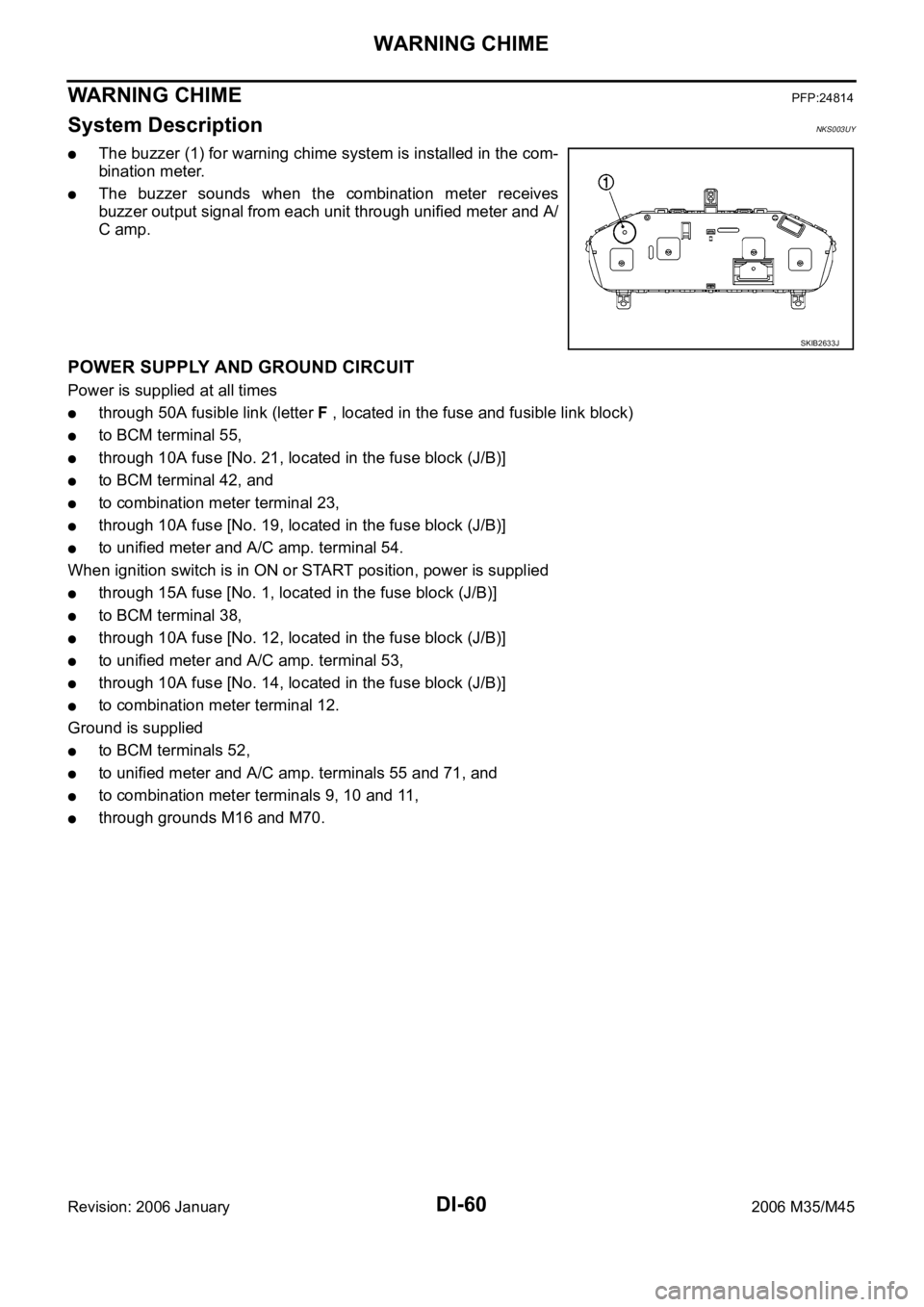
The buzzer (1) for warning chime system is installed in the com-
bination meter.
The buzzer sounds when the combination meter receives
buzzer output signal from each unit through unified meter and A/
C amp.
POWER SUPPLY AND GROUND CIRCUIT
Power is supplied at all times
through 50A fusible link (letter F , located in the fuse and fusible link block)
to BCM terminal 55,
through 10A fuse [No. 21, located in the fuse block (J/B)]
to BCM terminal 42, and
to combination meter terminal 23,
through 10A fuse [No. 19, located in the fuse block (J/B)]
to unified meter and A/C amp. terminal 54.
When ignition switch is in ON or START position, power is supplied
through 15A fuse [No. 1, located in the fuse block (J/B)]
to BCM terminal 38,
through 10A fuse [No. 12, located in the fuse block (J/B)]
to unified meter and A/C amp. terminal 53,
through 10A fuse [No. 14, located in the fuse block (J/B)]
to combination meter terminal 12.
Ground is supplied
to BCM terminals 52,
to unified meter and A/C amp. terminals 55 and 71, and
to combination meter terminals 9, 10 and 11,
through grounds M16 and M70.
SKIB2633J
Page 1513 of 5621

DI-80
LANE DEPARTURE WARNING SYSTEM
Revision: 2006 January2006 M35/M45
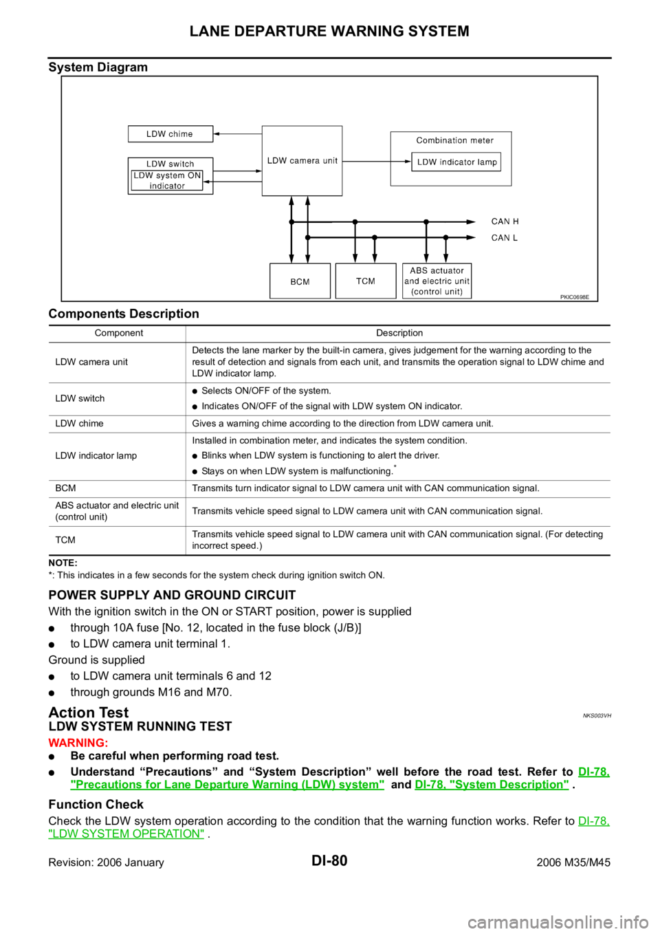
System Diagram
Components Description
NOTE:
*: This indicates in a few seconds for the system check during ignition switch ON.
POWER SUPPLY AND GROUND CIRCUIT
With the ignition switch in the ON or START position, power is supplied
through 10A fuse [No. 12, located in the fuse block (J/B)]
to LDW camera unit terminal 1.
Ground is supplied
to LDW camera unit terminals 6 and 12
through grounds M16 and M70.
Action TestNKS003VH
LDW SYSTEM RUNNING TEST
WAR NING :
Be careful when performing road test.
Understand “Precautions” and “System Description” well before the road test. Refer to DI-78,
"Precautions for Lane Departure Warning (LDW) system" and DI-78, "System Description" .
Function Check
Check the LDW system operation according to the condition that the warning function works. Refer to DI-78,
"LDW SYSTEM OPERATION" .
PKIC0698E
Component Description
LDW camera unitDetects the lane marker by the built-in camera, gives judgement for the warning according to the
result of detection and signals from each unit, and transmits the operation signal to LDW chime and
LDW indicator lamp.
LDW switch
Selects ON/OFF of the system.
Indicates ON/OFF of the signal with LDW system ON indicator.
LDW chime Gives a warning chime according to the direction from LDW camera unit.
LDW indicator lampInstalled in combination meter, and indicates the system condition.
Blinks when LDW system is functioning to alert the driver.
Stays on when LDW system is malfunctioning.*
BCM Transmits turn indicator signal to LDW camera unit with CAN communication signal.
ABS actuator and electric unit
(control unit)Transmits vehicle speed signal to LDW camera unit with CAN communication signal.
TCM Transmits vehicle speed signal to LDW camera unit with CAN communication signal. (For detecting
incorrect speed.)