2006 INFINITI M35 fuel
[x] Cancel search: fuelPage 1434 of 5621

DI-1
DRIVER INFORMATION SYSTEM
K ELECTRICAL
CONTENTS
C
D
E
F
G
H
I
J
L
M
SECTION DI
A
B
DI
Revision: 2006 January2006 M35/M45
DRIVER INFORMATION SYSTEM
PRECAUTION ............................................................ 3
Precautions for Supplemental Restraint System
(SRS) “AIR BAG” and “SEAT BELT PRE-TEN-
SIONER” .................................................................. 3
PREPARATION ........................................................... 4
Commercial Service Tools ........................................ 4
COMBINATION METERS ........................................... 5
System Description .................................................. 5
UNIFIED METER CONTROL UNIT ...................... 5
UNIFIED METER AND A/C AMP. ......................... 5
POWER SUPPLY AND GROUND CIRCUIT ........ 5
SPEEDOMETER ................................................... 6
TACHOMETER ..................................................... 6
WATER TEMPERATURE GAUGE ........................ 6
FUEL GAUGE ....................................................... 7
ODO/TRIP METER ............................................... 7
METER ILLUMINATION CONTROL ..................... 8
FAIL-SAFE ............................................................ 9
Arrangement of Combination Meter ....................... 10
Component Parts and Harness Connector Location .... 11
Internal Circuit ........................................................ 12
Wiring Diagram — METER — ................................ 13
Terminals and Reference Value for Combination
Meter ...................................................................... 15
Terminals and Reference Value for Unified Meter
and A/C Amp. ......................................................... 16
Self-Diagnosis Mode of Combination Meter ........... 17
SELF-DIAGNOSIS FUNCTION .......................... 17
OPERATION PROCEDURE ............................... 17
CONSULT-II Function (METER A/C AMP) ............. 18
Trouble Diagnosis .................................................. 18
HOW TO PERFORM TROUBLE DIAGNOSIS ... 18
PRELIMINARY CHECK ...................................... 18
Symptom Chart ...................................................... 18
Power Supply and Ground Circuit Inspection ........ 19
Vehicle Speed Signal Inspection ............................ 20
Engine Speed Signal Inspection ............................ 21
Engine Coolant Temperature Signal Inspection ..... 22
Fuel Level Sensor Signal Inspection ...................... 22
Fuel Gauge Pointer Fluctuates, Indicator Wrong Value or Varies ....................................................... 25
Fuel Gauge Does Not Move to FULL Position ....... 25
Electrical Components Inspection .......................... 26
CHECK FUEL LEVEL SENSOR UNIT ................ 26
Removal and Installation of Combination Meter ..... 27
REMOVAL ........................................................
... 27
INSTALLATION ................................................... 27
Disassembly and Assembly of Combination Meter ... 27
DISASSEMBLY ................................................... 27
ASSEMBLY ......................................................... 27
UNIFIED METER AND A/C AMP ...........................
... 28
System Description ................................................. 28
COMBINATION METER CONTROL FUNCTION ... 28
A/C AUTO AMP. FUNCTION ............................... 29
OTHER FUNCTIONS .......................................... 29
Schematic ............................................................... 30
CONSULT-II Function (METER A/C AMP) ............. 31
CONSULT-II BASIC OPERATION ....................... 31
SELF-DIAG RESULTS ........................................ 32
DATA MONITOR ................................................. 33
Power Supply and Ground Circuit Inspection ......... 35
DTC [U1000] CAN Communication Circuit ............. 36
DTC [B2202] Meter Communication Circuit ........... 36
DTC [B2205] Vehicle Speed Circuit ........................ 39
Removal and Installation of Unified Meter and A/C
Amp. ....................................................................... 39
REMOVAL ........................................................
... 39
INSTALLATION ................................................... 39
WARNING LAMPS .................................................... 40
System Description ................................................. 40
OIL PRESSURE WARNING LAMP ..................... 40
Component Parts and Harness Connector Location ... 41
Schematic ............................................................... 42
Wiring Diagram — WARN — .................................. 43
Oil Pressure Warning Lamp Stays Off (Ignition
Switch ON) ............................................................. 53
Oil Pressure Warning Lamp Does Not Turn Off (Oil
Pressure Is Normal) ................................................ 54
Electrical Component Inspection ............................ 55
OIL PRESSURE SWITCH ................................... 55
Page 1438 of 5621
COMBINATION METERS
DI-5
C
D
E
F
G
H
I
J
L
MA
B
DI
Revision: 2006 January2006 M35/M45
COMBINATION METERSPFP:24814
System DescriptionNKS003TV
UNIFIED METER CONTROL UNIT
Speedometer, odo/trip meter, tachometer, fuel gauge and water temperature gauge are controlled by the
unified meter control unit, which is built into the combination meter. Unified meter control unit receives sig-
nals from unified meter and A/C amp.
Warning lamp and indicator lamp of combination meter are controlled by signals drawn from the unified
meter and A/C amp.
Digital meter is adopted for odo/trip meter.
NOTE:
The record of the odo meter is kept even if the battery cable is disconnected. The record of the trip meter
is erased when the battery cable is disconnected.
Dot matrix LCD is adopted to display “push engine starter”, “A/T position” and “ICC system* ”.
Odo/trip meter and dot matrix LCD segments can be checked in self-diagnosis mode.
Meters/gauges can be checked in self-diagnosis mode.
*: With ICC system
UNIFIED METER AND A/C AMP.
Refer to DI-28, "COMBINATION METER CONTROL FUNCTION" in “UNIFIED METER AND A/C AMP”.
POWER SUPPLY AND GROUND CIRCUIT
Power is supplied at all times
through 10A fuse [No. 21, located in the fuse block (J/B)]
to combination meter terminal 23,
through 10A fuse [No. 19, located in the fuse block (J/B)]
to unified meter and A/C amp. terminal 54.
With the ignition switch in the ACC or ON position, power is supplied
through 10A fuse [No. 6, located in the fuse block (J/B)],
to combination meter terminal 2, and
to unified meter and A/C amp. terminal 41.
With the ignition switch in the ON or START position, power is supplied
through 10A fuse [No. 14, located in the fuse block (J/B)]
to combination meter terminal 12,
through 10A fuse [No. 12, located in the fuse block (J/B)]
to unified meter and A/C amp. terminal 53.
Ground is supplied
to combination meter terminals 9, 10 and 11
to unified meter and A/C amp. terminals 55 and 71
through grounds M16 and M70.
Page 1440 of 5621
COMBINATION METERS
DI-7
C
D
E
F
G
H
I
J
L
MA
B
DI
Revision: 2006 January2006 M35/M45
FUEL GAUGE
The fuel gauge indicates the approximate fuel level in the fuel tank.
The fuel gauge is regulated by a variable ground signal supplied
from unified meter and A/C amp. terminal 58
through the fuel level sensor unit and fuel pump (main) terminals 5 and 2, and
through the fuel level sensor unit (sub) terminals 2 and 1
to unified meter and A/C amp. terminal 42.
Unified meter and A/C amp. provides a fuel level signal to combination meter for fuel gauge with communica-
tion line between unified meter and A/C amp. and combination meter.
ODO/TRIP METER
ABS actuator and electric unit (control unit) converses a pulse signal from wheel sensor to vehicle speed
signal, and transmits vehicle speed signal to unified meter and A/C amp. with CAN communication.
Unified meter and A/C amp. converses vehicle speed signal to 8 pulse signal, and transmits to combina-
tion meter.
Combination meter processes the 8 pulse signal and the memory signals from the meter memory circuit.
Then the mileage is displayed.
How to Change The Display For Odo/trip Meter
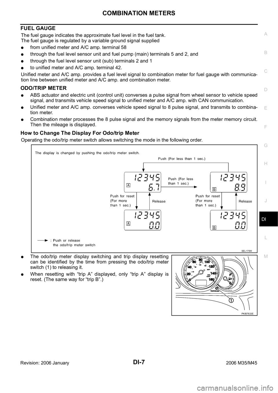
Operating the odo/trip meter switch allows switching the mode in the following order.
The odo/trip meter display switching and trip display resetting
can be identified by the time from pressing the odo/trip meter
switch (1) to releasing it.
When resetting with “trip A” displayed, only “trip A” display is
reset. (The same way for “trip B”.)
SEL175W
PKIB7633E
Page 1441 of 5621
DI-8
COMBINATION METERS
Revision: 2006 January2006 M35/M45
METER ILLUMINATION CONTROL
Meter illumination* is controlled by the unified meter control unit.
Ring illumination under normal operation and engine start excitement function can be turned ON/OFF with
pressing meter illumination control switch for more than 1 second.
*: Illumination for ring, meter face, pointer, dot matrix LCD and odo/trip meter
Daytime Mode
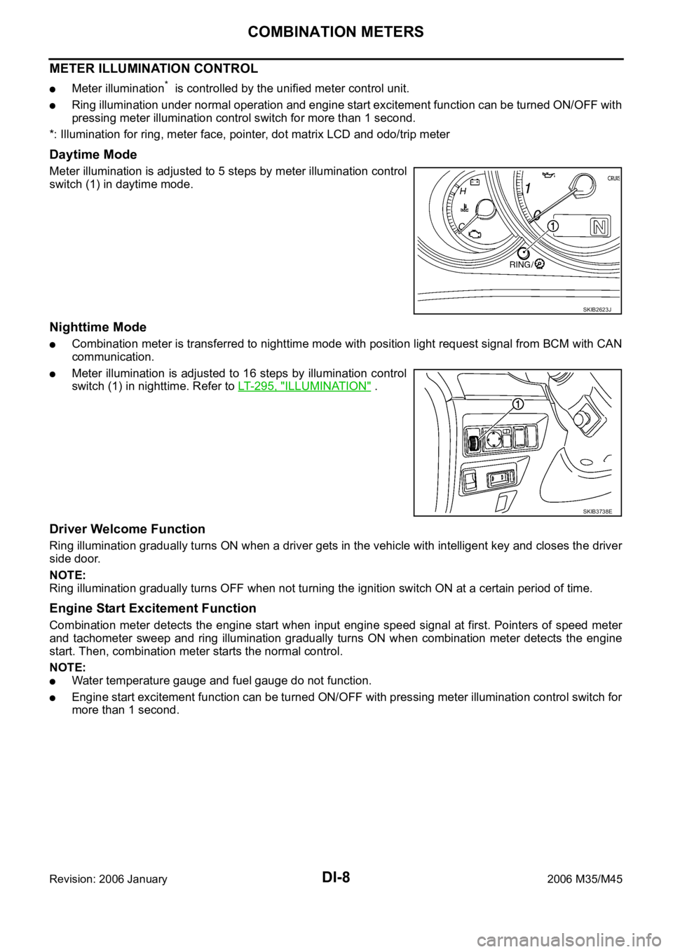
Meter illumination is adjusted to 5 steps by meter illumination control
switch (1) in daytime mode.
Nighttime Mode
Combination meter is transferred to nighttime mode with position light request signal from BCM with CAN
communication.
Meter illumination is adjusted to 16 steps by illumination control
switch (1) in nighttime. Refer to LT- 2 9 5 , "
ILLUMINATION" .
Driver Welcome Function
Ring illumination gradually turns ON when a driver gets in the vehicle with intelligent key and closes the driver
side door.
NOTE:
Ring illumination gradually turns OFF when not turning the ignition switch ON at a certain period of time.
Engine Start Excitement Function
Combination meter detects the engine start when input engine speed signal at first. Pointers of speed meter
and tachometer sweep and ring illumination gradually turns ON when combination meter detects the engine
start. Then, combination meter starts the normal control.
NOTE:
Water temperature gauge and fuel gauge do not function.
Engine start excitement function can be turned ON/OFF with pressing meter illumination control switch for
more than 1 second.
SKIB2623J
SKIB3738E
Page 1442 of 5621

COMBINATION METERS
DI-9
C
D
E
F
G
H
I
J
L
MA
B
DI
Revision: 2006 January2006 M35/M45
FA I L - S A F E
Combination meter performs fail-safe operation when unified meter and A/C amp. communication is malfunc-
tion.
Solution for communication error between the unified meter & A/C amp. and combination meter
Function Specifications
Speedometer
Reset to zero by suspending communication. Tachometer
Fuel gauge
Water temperature gauge
Illumination control Meter illumination When suspending communication, change to nighttime mode.
Dot matrix LCDPush engine starter
The display turns off by suspending communication. A/T position
ICC system
Buzzer The buzzer turns off by suspending communication.
Warning lamp/indicator lampABS warning lamp
The lamp turns on by suspending communication. Brake warning lamp
CRUISE warning lamp
VDC OFF indicator lamp
SLIP indicator lamp
A/T CHECK warning lamp
The lamp turns off by suspending communication. AWD warning lamp
Oil pressure warning lamp
Door warning lamp
Malfunction indicator lamp
CRUISE indicator lamp
SET indicator lamp
Low tire pressure warning lamp
AFS OFF indicator lamp
Front fog indicator lamp
High beam indicator
Turn signal indicator lamp
Key warning lamp
Page 1449 of 5621
DI-16
COMBINATION METERS
Revision: 2006 January2006 M35/M45
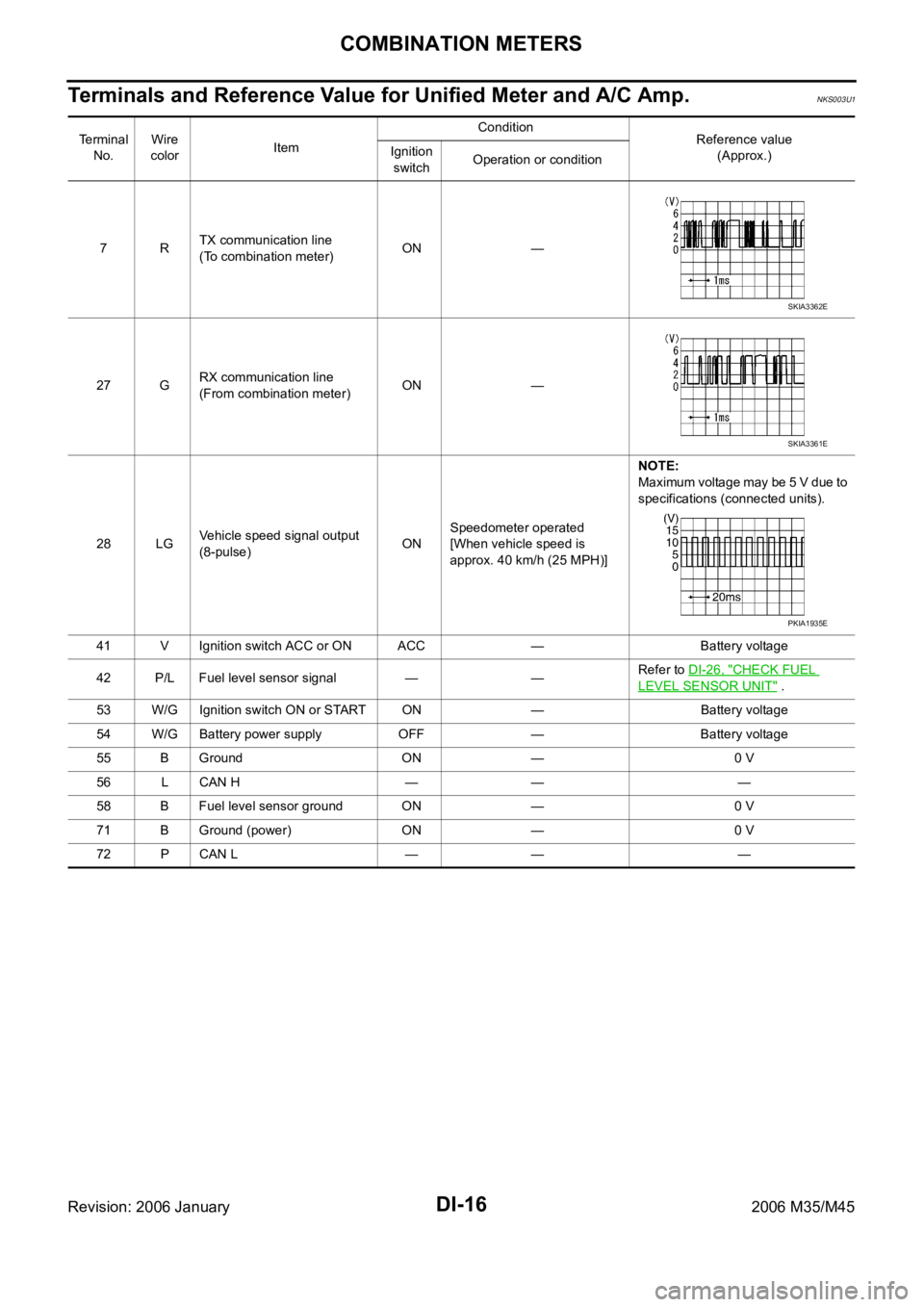
Terminals and Reference Value for Unified Meter and A/C Amp.NKS003U1
Te r m i n a l
No.Wire
colorItemCondition
Reference value
(Approx.) Ignition
switchOperation or condition
7RTX communication line
(To combination meter)ON —
27 GRX communication line
(From combination meter)ON —
28 LGVehicle speed signal output
(8-pulse)ONSpeedometer operated
[When vehicle speed is
approx. 40 km/h (25 MPH)]NOTE:
Maximum voltage may be 5 V due to
specifications (connected units).
41 V Ignition switch ACC or ON ACC — Battery voltage
42 P/L Fuel level sensor signal — —Refer to DI-26, "
CHECK FUEL
LEVEL SENSOR UNIT" .
53 W/G Ignition switch ON or START ON — Battery voltage
54 W/G Battery power supply OFF — Battery voltage
55 B Ground ON — 0 V
56 L CAN H — — —
58 B Fuel level sensor ground ON — 0 V
71 B Ground (power) ON — 0 V
72 P CAN L — — —
SKIA3362E
SKIA3361E
PKIA1935E
Page 1450 of 5621
COMBINATION METERS
DI-17
C
D
E
F
G
H
I
J
L
MA
B
DI
Revision: 2006 January2006 M35/M45
Self-Diagnosis Mode of Combination MeterNKS003U2
SELF-DIAGNOSIS FUNCTION
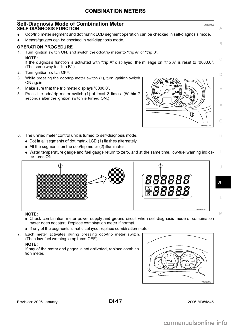
Odo/trip meter segment and dot matrix LCD segment operation can be checked in self-diagnosis mode.
Meters/gauges can be checked in self-diagnosis mode.
OPERATION PROCEDURE
1. Turn ignition switch ON, and switch the odo/trip meter to “trip A” or “trip B”.
NOTE:
If the diagnosis function is activated with “trip A” displayed, the mileage on “trip A” is reset to “0000.0”.
(The same way for “trip B”.)
2. Turn ignition switch OFF.
3. While pressing the odo/trip meter switch (1), turn ignition switch
ON again.
4. Make sure that the trip meter displays “0000.0”.
5. Press the odo/trip meter switch (1) at least 3 times. (Within 7
seconds after the ignition switch is turned ON.)
6. The unified meter control unit is turned to self-diagnosis mode.
Dot in all segments of dot matrix LCD (1) flashes alternately.
All the segments on the odo/trip meter (2) illuminates.
Water temperature gauge and fuel gauge return to zero, and at the same time, low-fuel warning indica-
tor turns ON.
NOTE:
Check combination meter power supply and ground circuit when self-diagnosis mode of combination
meter does not start. Replace combination meter if normal.
If any of the segments is not displayed, replace combination meter.
7. Each meter activates during pressing odo/trip meter switch.
(Then low-fuel warning lamp turns OFF.)
NOTE:
If any of the meter and gages is not activated, replace combina-
tion meter.
PKIB7633E
SKIB2939J
PKIB7636E
Page 1451 of 5621
DI-18
COMBINATION METERS
Revision: 2006 January2006 M35/M45
CONSULT-II Function (METER A/C AMP)NKS003U3
Refer to DI-31, "CONSULT-II Function (METER A/C AMP)" in “UNIFIED METER AND A/C AMP”.
Trouble DiagnosisNKS003U4
HOW TO PERFORM TROUBLE DIAGNOSIS
1. Confirm the symptom or customer complaint.
2. Perform preliminary check. Refer to DI-18, "
PRELIMINARY CHECK" .
3. According to the symptom chart, make sure the cause of the symptom and repair or replace applicable
parts. Refer to DI-18, "
Symptom Chart" .
4. Does the meter operate normally? If yes, GO TO 5. If no, GO TO 2.
5. INSPECTION END
PRELIMINARY CHECK
1. CHECK OPERATION SELF-DIAGNOSIS MODE OF COMBINATION METER
Perform self-diagnosis mode of combination meter. Refer to DI-17, "
OPERATION PROCEDURE" .
Does self
-diagnosis mode operate?
YES >> GO TO 2.
NO >> GO TO 3.
2. CHECK UNIFIED METER AND A/C AMP. (CONSULT-II)
Perform self-diagnosis of unified meter and A/C amp. Refer to DI-31, "
CONSULT-II Function (METER A/C
AMP)" .
Self
-diagnostic results content
No malfunction detected>>INSPECTION END
Malfunction detected>>Check applicable parts, and repair or replace corresponding parts.
3. CHECK POWER SUPPLY AND GROUND CIRCUIT OF COMBINATION METER
Check power supply and ground circuit of combination meter. Refer to DI-19, "
Power Supply and Ground Cir-
cuit Inspection" .
OK or NG
OK >> Replace combination meter.
NG >> Repair power supply and ground circuit of combination meter.
Symptom ChartNKS003U5
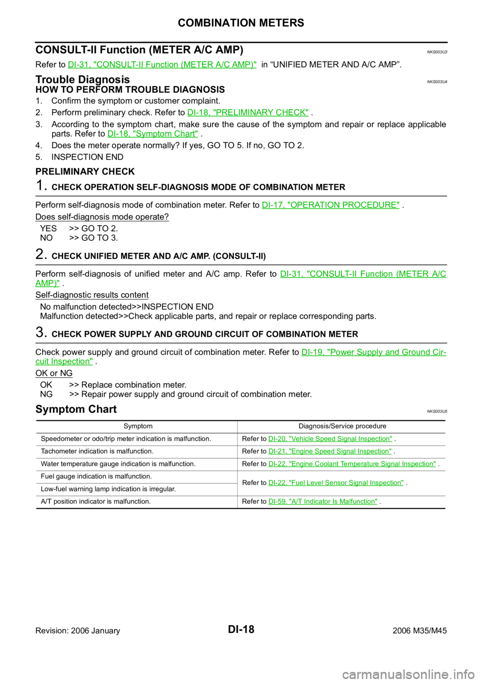
Symptom Diagnosis/Service procedure
Speedometer or odo/trip meter indication is malfunction. Refer to DI-20, "
Vehicle Speed Signal Inspection" .
Tachometer indication is malfunction. Refer to DI-21, "
Engine Speed Signal Inspection" .
Water temperature gauge indication is malfunction. Refer to DI-22, "
Engine Coolant Temperature Signal Inspection" .
Fuel gauge indication is malfunction.
Refer to DI-22, "
Fuel Level Sensor Signal Inspection" .
Low-fuel warning lamp indication is irregular.
A/T position indicator is malfunction. Refer to DI-59, "
A/T Indicator Is Malfunction" .