2006 INFINITI M35 battery location
[x] Cancel search: battery locationPage 3117 of 5621
![INFINITI M35 2006 Factory Service Manual EM-54
[VQ35DE]
FRONT TIMING CHAIN CASE
Revision: 2006 January2006 M35/M45
FRONT TIMING CHAIN CASEPFP:13599
Removal and InstallationNBS004NI
NOTE:
This section describes removal/installation procedure INFINITI M35 2006 Factory Service Manual EM-54
[VQ35DE]
FRONT TIMING CHAIN CASE
Revision: 2006 January2006 M35/M45
FRONT TIMING CHAIN CASEPFP:13599
Removal and InstallationNBS004NI
NOTE:
This section describes removal/installation procedure](/manual-img/42/57023/w960_57023-3116.png)
EM-54
[VQ35DE]
FRONT TIMING CHAIN CASE
Revision: 2006 January2006 M35/M45
FRONT TIMING CHAIN CASEPFP:13599
Removal and InstallationNBS004NI
NOTE:
This section describes removal/installation procedure of front timing chain case and timing chain related
parts without removing oil pan (upper) on the vehicle.
When oil pan (upper) needs to be removed or installed, or when rear timing chain case is removed or
installed, remove oil pans (upper and lower) first. Then remove front timing chain case, timing chain
related parts, and rear timing chain case in this order, and install in reverse order of removal. Refer to EM-
64, "TIMING CHAIN" .
Refer to EM-64, "TIMING CHAIN" for component parts location.
REMOVAL
1. Remove engine room cover (RH and LH). Refer to EM-14, "ENGINE ROOM COVER" .
2. Disconnect the battery cable from the negative terminal. Refer to SC-4, "
BATTERY" .
3. Remove engine cover with power tool. Refer to EM-19, "
INTAKE MANIFOLD COLLECTOR" .
4. Remove air duct (inlet) and air cleaner case assembly. Refer to EM-17, "
AIR CLEANER AND AIR DUCT"
.
5. Remove front and rear engine undercover with power tool.
6. Release the fuel pressure. Refer to EC-98, "
FUEL PRESSURE RELEASE" .
7. Drain engine oil. Refer to LU-9, "
Changing Engine Oil" .
CAUTION:
Perform this step when the engine is cold.
Do not spill engine oil on drive belts.
8. Drain engine coolant from radiator. Refer to CO-11, "
Changing Engine Coolant" .
CAUTION:
Perform this step when the engine is cold.
Do not spill engine coolant on drive belts.
9. Remove radiator hose (upper and lower) and A/T fluid cooler hose. Refer to CO-14, "
RADIATOR" .
10. Separate engine harnesses removing their brackets from front timing chain case.
11. Remove drive belts. Refer to EM-15, "
DRIVE BELTS" .
12. Remove intake manifold collectors (upper and lower). Refer to EM-19, "
INTAKE MANIFOLD COLLEC-
TOR" .
13. Remove power steering oil pump from bracket with piping connected, and temporarily secure it aside.
Refer to PS-29, "
POWER STEERING OIL PUMP" .
14. Remove power steering oil pump bracket. Refer to PS-29, "
POWER STEERING OIL PUMP" .
15. Remove alternator. Refer to SC-23, "
CHARGING SYSTEM" .
16. Remove water bypass hose, water hose clamp and idler pulley bracket from front timing chain case.
17. Remove intake valve timing control covers.
Loosen mounting bolts in reverse order as shown in the fig-
ure.
U s e t h e s e a l c u t t e r [ S S T: K V 1 0 1111 0 0 ( J 3 7 2 2 8 ) ] t o c u t l i q u i d
gasket for removal.
CAUTION:
Shaft is internally jointed with camshaft sprocket (INT) cen-
ter hole. When removing, keep it horizontal until it is com-
pletely disconnected.
SEM728G
Page 3308 of 5621
![INFINITI M35 2006 Factory Service Manual ENGINE ASSEMBLY
EM-245
[VK45DE]
C
D
E
F
G
H
I
J
K
L
MA
EM
Revision: 2006 January2006 M35/M45
Always use the support point specified for lifting.
Use either 2-pole lift type or separate type li INFINITI M35 2006 Factory Service Manual ENGINE ASSEMBLY
EM-245
[VK45DE]
C
D
E
F
G
H
I
J
K
L
MA
EM
Revision: 2006 January2006 M35/M45
Always use the support point specified for lifting.
Use either 2-pole lift type or separate type li](/manual-img/42/57023/w960_57023-3307.png)
ENGINE ASSEMBLY
EM-245
[VK45DE]
C
D
E
F
G
H
I
J
K
L
MA
EM
Revision: 2006 January2006 M35/M45
Always use the support point specified for lifting.
Use either 2-pole lift type or separate type lift as best you can. If board-on type is used for
unavoidable reasons, support at the rear axle jacking point with transmission jack or similar tool
before starting work, in preparation for the backward shift of center of gravity.
For supporting points for lifting and jacking point at rear axle, refer to GI-42, "Garage Jack and
Safety Stand and 2-Pole Lift" .
REMOVAL
Outline
At first, remove engine, transmission assembly with front suspension member from vehicle downward. Then
separate engine from transmission.
Preparation
1. Release fuel pressure. Refer to EC-809, "FUEL PRESSURE RELEASE" .
2. Drain engine coolant from radiator. Refer to CO-40, "
Changing Engine Coolant" .
CAUTION:
Perform this step when engine is cold.
Do not spill engine coolant on drive belts.
3. Disconnect both battery cables. Refer to SC-4, "
BATTERY" .
4. Remove crankshaft position sensor (POS) from transmission.
CAUTION:
Handle carefully to avoid dropping and shocks.
Do not disassemble.
Do not allow metal powder to adhere to magnetic part at sensor tip.
Do not place sensors in a location where they are exposed to magnetism.
5. Remove the following parts:
Front and rear engine undercover (power tool)
Air duct (inlet), air duct and air cleaner case assembly; Refer to EM-177, "AIR CLEANER AND AIR
DUCT" .
Front road wheels and tires (power tool)
Engine Room LH
1. Disconnect heater hoses, and install plugs to avoid leakage of engine coolant.
2. Disconnect wire bonding from exhaust manifold cover to vehicle.
3. Disconnect vacuum hose between vehicle and engine and set it aside.
4. Discharge refrigerant from A/C circuit. Refer to ATC-151, "
REFRIGERANT LINES" .
5. Remove A/C piping from A/C compressor, and temporarily fasten it on vehicle with a rope. Refer to AT C -
151, "REFRIGERANT LINES" .
Engine Room RH
1. Disconnect fuel feed hose and EVAP hose. Refer to EM-193, "FUEL INJECTOR AND FUEL TUBE" .
CAUTION:
Fit plugs onto disconnected hose to prevent fuel leak.
2. Disconnect ground cable (between vehicle and right bank cylinder head).
3. Disconnect vacuum hose between vehicle and engine and set it aside.
4. Disconnect reservoir tank of power steering oil pump from engine, and move it aside for easier work.
CAUTION:
When temporarily securing, keep reservoir tank upright to avoid a fluid leak.
Ve h i c le i n s i d e
Follow procedure below to disconnect engine room harness connectors at passenger room side, and tempo-
rarily secure them on engine.
1. Remove passenger-side kicking plate, dash side finisher, and glove box. Refer to EI-37, "
BODY SIDE
TRIM" and IP-10, "INSTRUMENT PANEL ASSEMBLY" .
2. Disconnect engine room harness connectors at unit sides TCM, ECM and other.
Page 3468 of 5621
PRECAUTIONS
GI-5
C
D
E
F
G
H
I
J
K
L
MB
GI
Revision: 2006 January2006 M35/M45
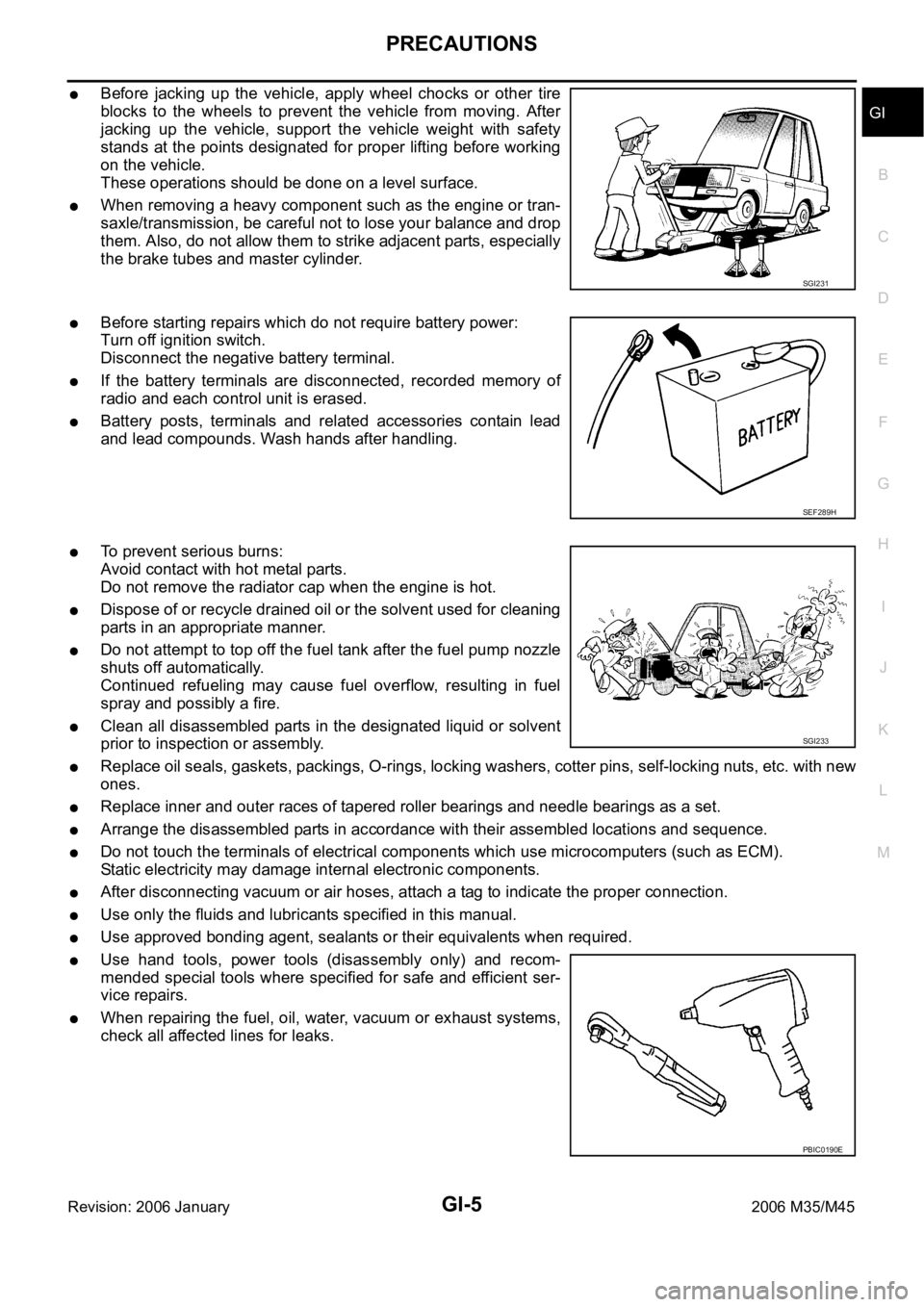
Before jacking up the vehicle, apply wheel chocks or other tire
blocks to the wheels to prevent the vehicle from moving. After
jacking up the vehicle, support the vehicle weight with safety
stands at the points designated for proper lifting before working
on the vehicle.
These operations should be done on a level surface.
When removing a heavy component such as the engine or tran-
saxle/transmission, be careful not to lose your balance and drop
them. Also, do not allow them to strike adjacent parts, especially
the brake tubes and master cylinder.
Before starting repairs which do not require battery power:
Turn off ignition switch.
Disconnect the negative battery terminal.
If the battery terminals are disconnected, recorded memory of
radio and each control unit is erased.
Battery posts, terminals and related accessories contain lead
and lead compounds. Wash hands after handling.
To prevent serious burns:
Avoid contact with hot metal parts.
Do not remove the radiator cap when the engine is hot.
Dispose of or recycle drained oil or the solvent used for cleaning
parts in an appropriate manner.
Do not attempt to top off the fuel tank after the fuel pump nozzle
shuts off automatically.
Continued refueling may cause fuel overflow, resulting in fuel
spray and possibly a fire.
Clean all disassembled parts in the designated liquid or solvent
prior to inspection or assembly.
Replace oil seals, gaskets, packings, O-rings, locking washers, cotter pins, self-locking nuts, etc. with new
ones.
Replace inner and outer races of tapered roller bearings and needle bearings as a set.
Arrange the disassembled parts in accordance with their assembled locations and sequence.
Do not touch the terminals of electrical components which use microcomputers (such as ECM).
Static electricity may damage internal electronic components.
After disconnecting vacuum or air hoses, attach a tag to indicate the proper connection.
Use only the fluids and lubricants specified in this manual.
Use approved bonding agent, sealants or their equivalents when required.
Use hand tools, power tools (disassembly only) and recom-
mended special tools where specified for safe and efficient ser-
vice repairs.
When repairing the fuel, oil, water, vacuum or exhaust systems,
check all affected lines for leaks.
SGI231
SEF289H
SGI233
PBIC0190E
Page 3475 of 5621
GI-12
HOW TO USE THIS MANUAL
Revision: 2006 January2006 M35/M45
How to Follow Trouble DiagnosesNAS0007M
DESCRIPTION
NOTICE:
Trouble diagnoses indicate work procedures required to diagnose problems effectively. Observe the following
instructions before diagnosing.
1.Before performing trouble diagnoses, read the “Preliminary Check”, the “Symptom Chart” or the
“Work Flow”.
2.After repairs, re-check that the problem has been completely eliminated.
3.Refer to Component Parts and Harness Connector Location for the Systems described in each
section for identification/location of components and harness connectors.
4.Refer to the Circuit Diagram for quick pinpoint check.
If you need to check circuit continuity between harness connectors in more detail, such as when a
sub-harness is used, refer to Wiring Diagram in each individual section and Harness Layout in PG
section for identification of harness connectors.
5.When checking circuit continuity, ignition switch should be OFF.
6.Before checking voltage at connectors, check battery voltage.
7.After accomplishing the Diagnostic Procedures and Electrical Components Inspection, make sure
that all harness connectors are reconnected as they were.
HOW TO FOLLOW TEST GROUPS IN TROUBLE DIAGNOSES
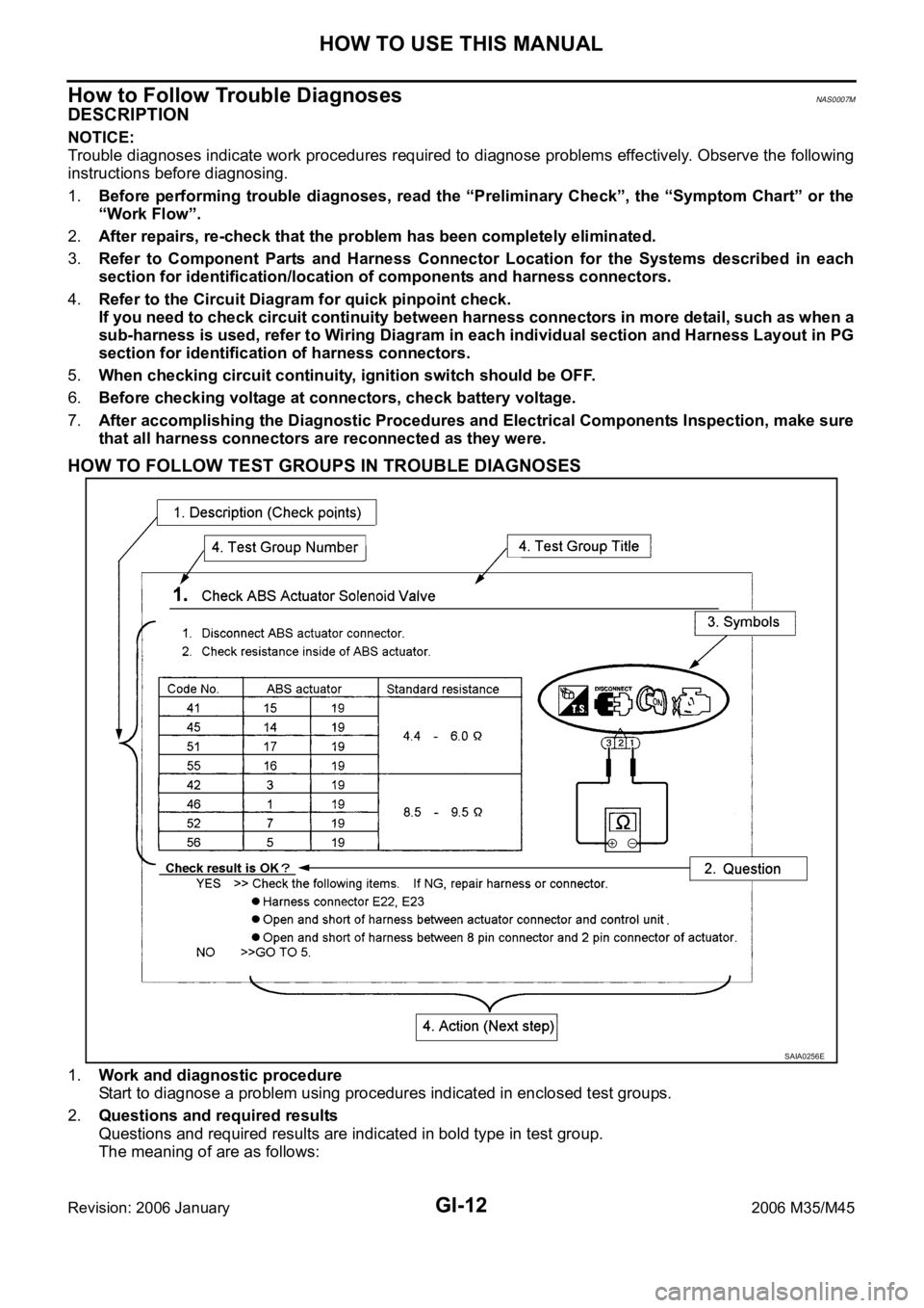
1.Work and diagnostic procedure
Start to diagnose a problem using procedures indicated in enclosed test groups.
2.Questions and required results
Questions and required results are indicated in bold type in test group.
The meaning of are as follows:
SAIA0256E
Page 3481 of 5621
GI-18
HOW TO USE THIS MANUAL
Revision: 2006 January2006 M35/M45
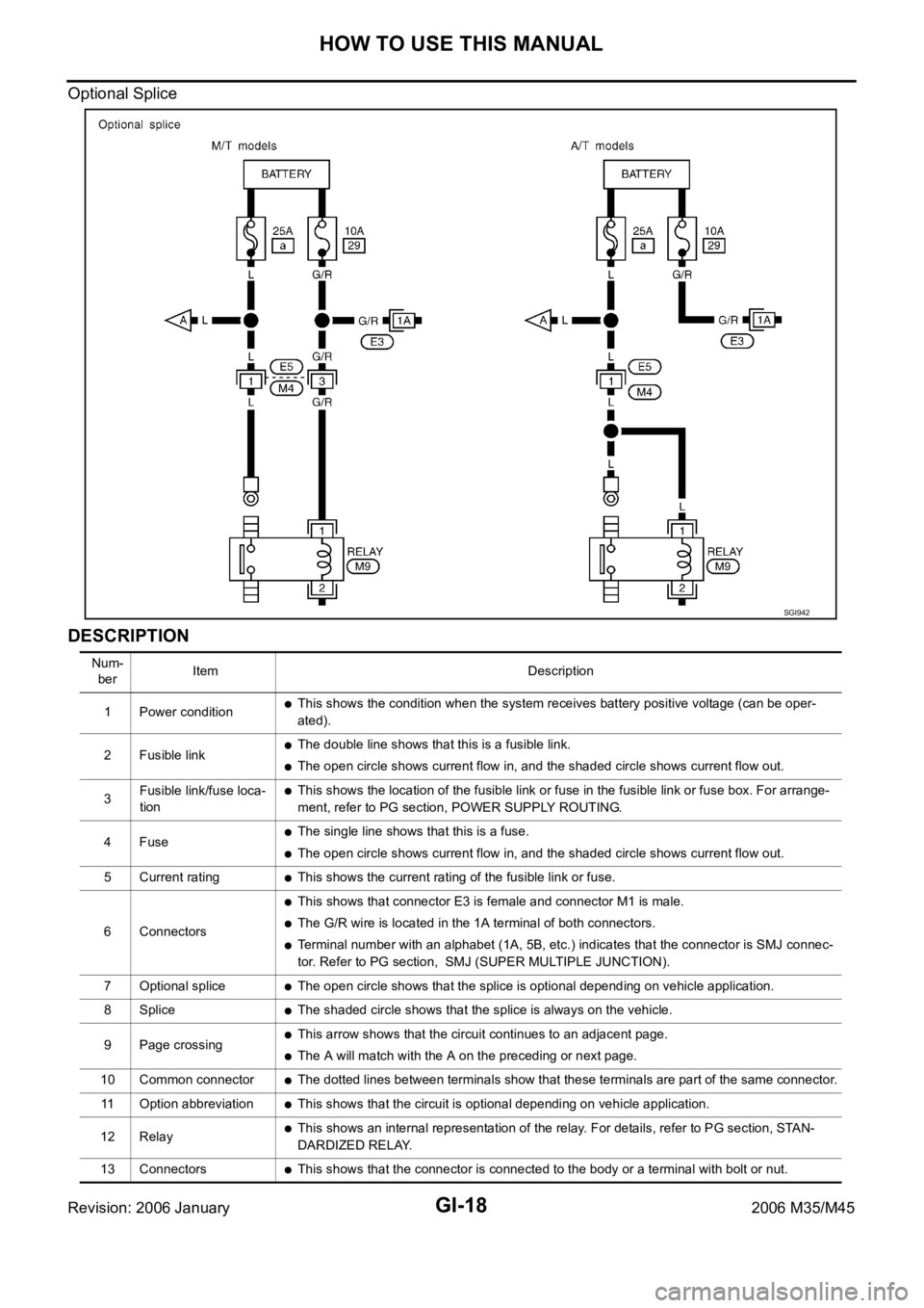
Optional Splice
DESCRIPTION
SGI942
Num-
berItem Description
1 Power condition
This shows the condition when the system receives battery positive voltage (can be oper-
ated).
2 Fusible link
The double line shows that this is a fusible link.
The open circle shows current flow in, and the shaded circle shows current flow out.
3Fusible link/fuse loca-
tion
This shows the location of the fusible link or fuse in the fusible link or fuse box. For arrange-
ment, refer to PG section, POWER SUPPLY ROUTING.
4Fuse
The single line shows that this is a fuse.
The open circle shows current flow in, and the shaded circle shows current flow out.
5 Current rating
This shows the current rating of the fusible link or fuse.
6 Connectors
This shows that connector E3 is female and connector M1 is male.
The G/R wire is located in the 1A terminal of both connectors.
Terminal number with an alphabet (1A, 5B, etc.) indicates that the connector is SMJ connec-
tor. Refer to PG section, SMJ (SUPER MULTIPLE JUNCTION).
7 Optional splice
The open circle shows that the splice is optional depending on vehicle application.
8 Splice
The shaded circle shows that the splice is always on the vehicle.
9 Page crossing
This arrow shows that the circuit continues to an adjacent page.
The A will match with the A on the preceding or next page.
10 Common connector
The dotted lines between terminals show that these terminals are part of the same connector.
11 Option abbreviation
This shows that the circuit is optional depending on vehicle application.
12 Relay
This shows an internal representation of the relay. For details, refer to PG section, STAN-
DARDIZED RELAY.
13 Connectors
This shows that the connector is connected to the body or a terminal with bolt or nut.
Page 3553 of 5621
![INFINITI M35 2006 Factory Service Manual GW-34
POWER WINDOW SYSTEM
Revision: 2006 January2006 M35/M45
BCM Power Supply and Ground Circuit CheckNIS0021R
1. CHECK FUSE
Check 15A fuse [No. 1, located in fuse block (J/B)]
Check 10A fuse [No. 21, INFINITI M35 2006 Factory Service Manual GW-34
POWER WINDOW SYSTEM
Revision: 2006 January2006 M35/M45
BCM Power Supply and Ground Circuit CheckNIS0021R
1. CHECK FUSE
Check 15A fuse [No. 1, located in fuse block (J/B)]
Check 10A fuse [No. 21,](/manual-img/42/57023/w960_57023-3552.png)
GW-34
POWER WINDOW SYSTEM
Revision: 2006 January2006 M35/M45
BCM Power Supply and Ground Circuit CheckNIS0021R
1. CHECK FUSE
Check 15A fuse [No. 1, located in fuse block (J/B)]
Check 10A fuse [No. 21, located in fuse block (J/B)]
Check 50A fusible link (letter F , located in the fuse and fusible link box).
NOTE:
Refer to GW-13, "
Component Parts and Harness Connector Location" .
OK or NG
OK >> GO TO 2.
NG >> If fuse is blown out, be sure to eliminate cause of malfunction before installing new fuse. Refer to
PG-3, "
POWER SUPPLY ROUTING CIRCUIT" .
2. CHECK POWER SUPPLY CIRCUIT
Check voltage between BCM connector and ground.
OK or NG
OK >> GO TO 3.
NG >> Check BCM power supply circuit for open or short.
3. CHECK GROUND CIRCUIT
1. Turn ignition switch OFF.
2. Disconnect BCM connector.
3. Check continuity between BCM connector and ground.
OK or NG
OK >> Power supply and ground circuit are OK.
NG >> Check BCM ground circuit for open or short.
Te r m i n a l s
Condition of
ignition switchVoltage (V)
(Approx.) (+)
(–)
BCM connector Terminal
M1 38
GroundON
Battery voltage
M242
OFF
55
PIIB5934E
BCM connector Terminal
GroundContinuity
M2 52 Yes
PIIB5935E
Page 3604 of 5621
REAR WINDOW DEFOGGER
GW-85
C
D
E
F
G
H
J
K
L
MA
B
GW
Revision: 2006 January2006 M35/M45
BCM Power Supply and Ground Circuit CheckNIS0022R
First perform the “SELF-DIAG RESULTS” in “BCM” with CONSULT-II, when perform the each trouble
diagnosis. Refer to BCS-15, "
CAN Communication Inspection Using CONSULT-II (Self-Diagnosis)" .
1. CHECK FUSE
Check 15A fuse [No.1, located in the fuse block (J/B)]
Check 10A fuse [No.21, located in the fuse block (J/B)]
Check 50A fusible link (letter F located in the fuse and fusible link box).
NOTE:
Refer to GW-73, "
Component Parts and Harness Connector Location" .
OK or NG
OK >> GO TO 2.
NG >> If fuse is blown out, be sure to eliminate cause of malfunction before installing new fuse. Refer to
PG-3, "
POWER SUPPLY ROUTING CIRCUIT" .
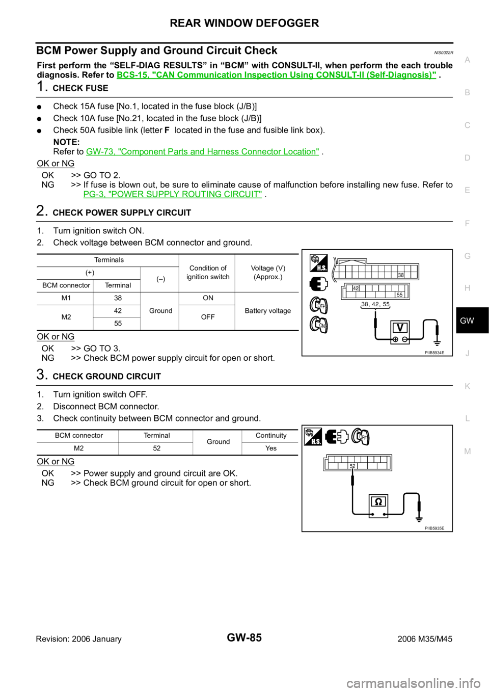
2. CHECK POWER SUPPLY CIRCUIT
1. Turn ignition switch ON.
2. Check voltage between BCM connector and ground.
OK or NG
OK >> GO TO 3.
NG >> Check BCM power supply circuit for open or short.
3. CHECK GROUND CIRCUIT
1. Turn ignition switch OFF.
2. Disconnect BCM connector.
3. Check continuity between BCM connector and ground.
OK or NG
OK >> Power supply and ground circuit are OK.
NG >> Check BCM ground circuit for open or short.
Terminals
Condition of
ignition switchVoltage (V)
(Approx.) (+)
(–)
BCM connector Terminal
M1 38
GroundON
Battery voltage
M242
OFF
55
PIIB5934E
BCM connector Terminal
GroundContinuity
M2 52 Yes
PIIB5935E
Page 3605 of 5621
GW-86
REAR WINDOW DEFOGGER
Revision: 2006 January2006 M35/M45
Rear Window Defogger Switch Circuit CheckNIS0022S
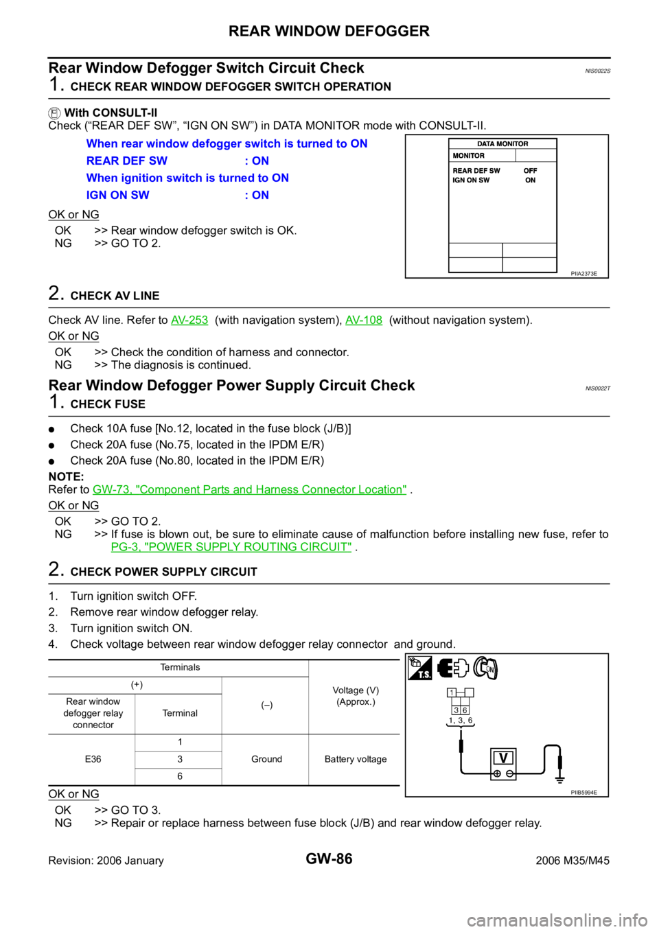
1. CHECK REAR WINDOW DEFOGGER SWITCH OPERATION
With CONSULT-II
Check (“REAR DEF SW”, “IGN ON SW”) in DATA MONITOR mode with CONSULT-II.
OK or NG
OK >> Rear window defogger switch is OK.
NG >> GO TO 2.
2. CHECK AV LINE
Check AV line. Refer to AV- 2 5 3
(with navigation system), AV- 1 0 8 (without navigation system).
OK or NG
OK >> Check the condition of harness and connector.
NG >> The diagnosis is continued.
Rear Window Defogger Power Supply Circuit CheckNIS0022T
1. CHECK FUSE
Check 10A fuse [No.12, located in the fuse block (J/B)]
Check 20A fuse (No.75, located in the IPDM E/R)
Check 20A fuse (No.80, located in the IPDM E/R)
NOTE:
Refer to GW-73, "
Component Parts and Harness Connector Location" .
OK or NG
OK >> GO TO 2.
NG >> If fuse is blown out, be sure to eliminate cause of malfunction before installing new fuse, refer to
PG-3, "
POWER SUPPLY ROUTING CIRCUIT" .
2. CHECK POWER SUPPLY CIRCUIT
1. Turn ignition switch OFF.
2. Remove rear window defogger relay.
3. Turn ignition switch ON.
4. Check voltage between rear window defogger relay connector and ground.
OK or NG
OK >> GO TO 3.
NG >> Repair or replace harness between fuse block (J/B) and rear window defogger relay. When rear window defogger switch is turned to ON
REAR DEF SW : ON
When ignition switch is turned to ON
IGN ON SW : ON
PIIA2373E
Terminals
Voltage (V)
(Approx.) (+)
(–) Rear window
defogger relay
connectorTerminal
E361
Ground Battery voltage 3
6
PIIB5994E