2006 INFINITI M35 Coolant
[x] Cancel search: CoolantPage 3146 of 5621
![INFINITI M35 2006 Factory Service Manual TIMING CHAIN
EM-83
[VQ35DE]
C
D
E
F
G
H
I
J
K
L
MA
EM
Revision: 2006 January2006 M35/M45
Summary of the inspection items:
* Transmission/transaxle/CVT fluid, power steering fluid, brake fluid, etc. It](/manual-img/42/57023/w960_57023-3145.png "INFINITI M35 2006 Factory Service Manual TIMING CHAIN
EM-83
[VQ35DE]
C
D
E
F
G
H
I
J
K
L
MA
EM
Revision: 2006 January2006 M35/M45
Summary of the inspection items:
* Transmission/transaxle/CVT fluid, power steering fluid, brake fluid, etc. It")
TIMING CHAIN
EM-83
[VQ35DE]
C
D
E
F
G
H
I
J
K
L
MA
EM
Revision: 2006 January2006 M35/M45
Summary of the inspection items:
* Transmission/transaxle/CVT fluid, power steering fluid, brake fluid, etc. Item Before starting engine Engine running After engine stopped
Engine coolant Level Leakage Level
Engine oil Level Leakage Level
Other oils and fluid* Level Leakage Level
Fuel Leakage Leakage Leakage
Page 3155 of 5621
![INFINITI M35 2006 Factory Service Manual EM-92
[VQ35DE]
CAMSHAFT
Revision: 2006 January2006 M35/M45
INSPECTION AFTER INSTALLATION
Inspection of Camshaft Sprocket (INT) Oil Groove
CAUTION:
Perform this inspection only when DTC P0011 or](/manual-img/42/57023/w960_57023-3154.png "INFINITI M35 2006 Factory Service Manual EM-92
[VQ35DE]
CAMSHAFT
Revision: 2006 January2006 M35/M45
INSPECTION AFTER INSTALLATION
Inspection of Camshaft Sprocket (INT) Oil Groove
CAUTION:
Perform this inspection only when DTC P0011 or")
EM-92
[VQ35DE]
CAMSHAFT
Revision: 2006 January2006 M35/M45
INSPECTION AFTER INSTALLATION
Inspection of Camshaft Sprocket (INT) Oil Groove
CAUTION:
Perform this inspection only when DTC P0011 or P0021 are detected in self-diagnostic results of
CONSULT-II and it is directed according to inspection procedure of EC section. Refer to EC-137,
"SELF-DIAG RESULTS MODE" .
Check when engine ins cold so as to prevent burns from any splashing engine oil.
1. Check the engine oil level. Refer to LU-7, "
ENGINE OIL" .
2. Perform the following procedure so as to prevent the engine from being unintentionally started while
checking.
a. Release fuel pressure. Refer to EC-98, "
FUEL PRESSURE RELEASE" .
b. Disconnect ignition coil and injector harness connectors.
3. Remove intake valve timing control solenoid valve. Refer to EM-84, "
CAMSHAFT" .
4. Crank the engine, and then make sure that engine oil comes out
from camshaft bracket (No. 1) oil hole. End crank after checking.
WA R N I N G :
Be careful not to touch rotating parts (drive belts, idler pul-
ley, and crankshaft pulley, etc.).
CAUTION:
Engine oil may squirt from intake valve timing control sole-
noid valve installation hole during cranking. Use a shop
cloth to prevent the engine components and the vehicle. Do
not allow engine oil to get on rubber components such as
drive belt or engine mount insulators. Immediately wipe off
any splashed engine oil.
Clean oil groove between oil strainer and intake valve timing control solenoid valve if engine oil does not
come out from camshaft bracket (No. 1) oil hole. Refer to LU-5, "
LUBRICATION SYSTEM" .
5. Remove components between intake valve timing control solenoid valve and camshaft sprocket (INT),
and then check each oil groove for clogging.
Clean oil groove if necessary. Refer to LU-5, "LUBRICATION SYSTEM" .
6. After inspection, install removed parts.
Inspection for Leaks
The following are procedures for checking fluids leak, lubricates leak.
Before starting engine, check oil/fluid levels including engine coolant and engine oil. If less than required
quantity, fill to the specified level. Refer to MA-12, "
RECOMMENDED FLUIDS AND LUBRICANTS" .
Use procedure below to check for fuel leakage.
–Turn ignition switch “ON” (with engine stopped). With fuel pressure applied to fuel piping, check for fuel
leakage at connection points.
–Start engine. With engine speed increased, check again for fuel leakage at connection points.
Run engine to check for unusual noise and vibration.
NOTE:
If hydraulic pressure inside timing chain tensioner drops after removal/installation, slack in the guide may
generate a pounding noise during and just after engine start. However, this is normal. Noise will stop after
hydraulic pressure rises.
Warm up engine thoroughly to make sure there is no leakage of fuel, or any oil/fluids including engine oil
and engine coolant.
Bleed air from lines and hoses of applicable lines, such as in cooling system.
After cooling down engine, again check oil/fluid levels including engine oil and engine coolant. Refill to the
specified level, if necessary.
PBIC2869E
Page 3156 of 5621
![INFINITI M35 2006 Factory Service Manual CAMSHAFT
EM-93
[VQ35DE]
C
D
E
F
G
H
I
J
K
L
MA
EM
Revision: 2006 January2006 M35/M45
Summary of the inspection items:
* Transmission/transaxle/CVT fluid, power steering fluid, brake fluid, etc.
Va l v](/manual-img/42/57023/w960_57023-3155.png "INFINITI M35 2006 Factory Service Manual CAMSHAFT
EM-93
[VQ35DE]
C
D
E
F
G
H
I
J
K
L
MA
EM
Revision: 2006 January2006 M35/M45
Summary of the inspection items:
* Transmission/transaxle/CVT fluid, power steering fluid, brake fluid, etc.
Va l v")
CAMSHAFT
EM-93
[VQ35DE]
C
D
E
F
G
H
I
J
K
L
MA
EM
Revision: 2006 January2006 M35/M45
Summary of the inspection items:
* Transmission/transaxle/CVT fluid, power steering fluid, brake fluid, etc.
Va l v e C l e a r a n c eNBS004NN
INSPECTION
Perform inspection as follows after removal, installation or replacement of camshaft or valve-related parts, or if
there is unusual engine conditions regarding valve clearance.
In cases of removing/installing or replacing camshaft and valve-
related parts, or of unusual engine conditions due to changes in
valve clearance (found malfunctions during stating, idling or causing
noise), perform inspection as follows:
1. Remove rocker covers (right and left bank). Refer to EM-51, "
ROCKER COVER" .
2. Measure the valve clearance as follows:
a. Set No. 1 cylinder at TDC of its compression stroke.
Rotate crankshaft pulley clockwise to align timing mark
(grooved line without color) with timing indicator.
Make sure that intake and exhaust cam nose on No. 1 cylin-
der (engine front side of right bank) are located as shown in
the figure.
If not, turn crankshaft one revolution (360 degrees) and align
as shown in the figure.
Item Before starting engine Engine running After engine stopped
Engine coolant Level Leakage Level
Engine oil Level Leakage Level
Other oils and fluid* Level Leakage Level
Fuel Leakage Leakage Leakage
SEM713A
KBIA1717J
SEM418G
Page 3167 of 5621
EM-104
[VQ35DE]
CYLINDER HEAD
Revision: 2006 January2006 M35/M45
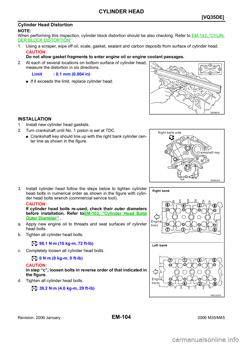
Cylinder Head Distortion
NOTE:
When performing this inspection, cylinder block distortion should be also checking. Refer to EM-143, "
CYLIN-
DER BLOCK DISTORTION" .
1. Using a scraper, wipe off oil, scale, gasket, sealant and carbon deposits from surface of cylinder head.
CAUTION:
Do not allow gasket fragments to enter engine oil or engine coolant passages.
2. At each of several locations on bottom surface of cylinder head,
measure the distortion in six directions.
If it exceeds the limit, replace cylinder head.
INSTALLATION
1. Install new cylinder head gaskets.
2. Turn crankshaft until No. 1 piston is set at TDC.
Crankshaft key should line up with the right bank cylinder cen-
ter line as shown in the figure.
3. Install cylinder head follow the steps below to tighten cylinder
head bolts in numerical order as shown in the figure with cylin-
der head bolts wrench (commercial service tool).
CAUTION:
If cylinder head bolts re-used, check their outer diameters
before installation. Refer toEM-103, "
Cylinder Head Bolts
Outer Diameter" .
a. Apply new engine oil to threads and seat surfaces of cylinder
head bolts.
b. Tighten all cylinder head bolts.
c. Completely loosen all cylinder head bolts.
CAUTION:
In step “c”, loosen bolts in reverse order of that indicated in
the figure.
d. Tighten all cylinder head bolts.Limit : 0.1 mm (0.004 in)
SEM861E
SEM532G
: 98.1 Nꞏm (10 kg-m, 72 ft-lb)
: 0 Nꞏm (0 kg-m, 0 ft-lb)
: 39.2 Nꞏm (4.0 kg-m, 29 ft-lb)
PBIC2057E
Page 3168 of 5621
![INFINITI M35 2006 Factory Service Manual CYLINDER HEAD
EM-105
[VQ35DE]
C
D
E
F
G
H
I
J
K
L
MA
EM
Revision: 2006 January2006 M35/M45
e. Turn all cylinder head bolts 90 degrees clockwise (angle tighten-
ing).
CAUTION:
Check the tightening a](/manual-img/42/57023/w960_57023-3167.png "INFINITI M35 2006 Factory Service Manual CYLINDER HEAD
EM-105
[VQ35DE]
C
D
E
F
G
H
I
J
K
L
MA
EM
Revision: 2006 January2006 M35/M45
e. Turn all cylinder head bolts 90 degrees clockwise (angle tighten-
ing).
CAUTION:
Check the tightening a")
CYLINDER HEAD
EM-105
[VQ35DE]
C
D
E
F
G
H
I
J
K
L
MA
EM
Revision: 2006 January2006 M35/M45
e. Turn all cylinder head bolts 90 degrees clockwise (angle tighten-
ing).
CAUTION:
Check the tightening angle by using the angle wrench
(SST). Avoid judgment by visual inspection without SST.
Check tightening angle indicated on the angle wrench indica-
tor plate.
f. Turn all cylinder head bolts 90 degrees clockwise again (angle
tightening).
4. After installing cylinder head, measure distance between front
end faces of cylinder block and cylinder head (left and right
banks).
If measured value is out of the standard, re-install cylinder
head.
5. Install in the reverse order of removal after this step.
INSPECTION AFTER INSTALLATION
Inspection for Leaks
The following are procedures for checking fluids leak, lubricates leak and exhaust gases leak.
Before starting engine, check oil/fluid levels including engine coolant and engine oil. If less than required
quantity, fill to the specified level. Refer to MA-12, "
RECOMMENDED FLUIDS AND LUBRICANTS" .
Use procedure below to check for fuel leakage.
–Turn ignition switch “ON” (with engine stopped). With fuel pressure applied to fuel piping, check for fuel
leakage at connection points.
–Start engine. With engine speed increased, check again for fuel leakage at connection points.
Run engine to check for unusual noise and vibration.
Warm up engine thoroughly to make sure there is no leakage of fuel, exhaust gases, or any oil/fluids
including engine oil and engine coolant.
Bleed air from lines and hoses of applicable lines, such as in cooling system.
After cooling down engine, again check oil/fluid levels including engine oil and engine coolant. Refill to the
specified level, if necessary.
Summary of the inspection items:
* Transmission/transaxle/CVT fluid, power steering fluid, brake fluid, etc.
PBIC0888E
Standard : 14.1 - 14.9 mm (0.555 - 0.587 in)
EMQ0662D
Item Before starting engine Engine running After engine stopped
Engine coolant Level Leakage Level
Engine oil Level Leakage Level
Other oils and fluid* Level Leakage Level
Fuel Leakage Leakage Leakage
Exhaust gases — Leakage —
Page 3176 of 5621
![INFINITI M35 2006 Factory Service Manual ENGINE ASSEMBLY
EM-113
[VQ35DE]
C
D
E
F
G
H
I
J
K
L
MA
EM
Revision: 2006 January2006 M35/M45
ENGINE ASSEMBLYPFP:10001
Components (2WD Models)NBS004NW
Removal and Installation (2WD Models)NBS004NX
WAR](/manual-img/42/57023/w960_57023-3175.png "INFINITI M35 2006 Factory Service Manual ENGINE ASSEMBLY
EM-113
[VQ35DE]
C
D
E
F
G
H
I
J
K
L
MA
EM
Revision: 2006 January2006 M35/M45
ENGINE ASSEMBLYPFP:10001
Components (2WD Models)NBS004NW
Removal and Installation (2WD Models)NBS004NX
WAR")
ENGINE ASSEMBLY
EM-113
[VQ35DE]
C
D
E
F
G
H
I
J
K
L
MA
EM
Revision: 2006 January2006 M35/M45
ENGINE ASSEMBLYPFP:10001
Components (2WD Models)NBS004NW
Removal and Installation (2WD Models)NBS004NX
WAR NING :
Situate the vehicle on a flat and solid surface.
Place chocks at front and back of rear wheels.
For engines not equipped with engine slingers, attach proper slingers and bolts described in
PARTS CATALOG.
CAUTION:
Always be careful to work safely, avoid forceful or uninstructed operations.
Do not start working until exhaust system and engine coolant are cool enough.
If items or work required are not covered by the engine section, refer to the applicable sections.
Always use the support point specified for lifting.
Use either 2-pole lift type or separate type lift as best you can. If board-on type is used for
unavoidable reasons, support at rear axle jacking point with transmission jack or similar tool
before starting work, in preparation for the backward shift of center of gravity.
For supporting points for lifting and jacking point at rear axle, refer to GI-42, "Garage Jack and
Safety Stand and 2-Pole Lift" .
1. Engine mounting bracket (RH) 2. Heat insulator (RH) 3. Engine mounting insulator (RH)
4. Engine mounting bracket (LH) 5. Heat insulator (LH) 6. Engine mounting insulator (LH)
7. Rear engine mounting member 8. Dynamic damper 9. Engine mounting insulator (rear)
10. Dynamic damper
A. Front mark
PBIC3363E
Page 3177 of 5621
![INFINITI M35 2006 Factory Service Manual EM-114
[VQ35DE]
ENGINE ASSEMBLY
Revision: 2006 January2006 M35/M45
REMOVAL
Outline
At first, remove the engine and the transmission assembly with front suspension member from vehicle down-
ward. Then](/manual-img/42/57023/w960_57023-3176.png "INFINITI M35 2006 Factory Service Manual EM-114
[VQ35DE]
ENGINE ASSEMBLY
Revision: 2006 January2006 M35/M45
REMOVAL
Outline
At first, remove the engine and the transmission assembly with front suspension member from vehicle down-
ward. Then")
EM-114
[VQ35DE]
ENGINE ASSEMBLY
Revision: 2006 January2006 M35/M45
REMOVAL
Outline
At first, remove the engine and the transmission assembly with front suspension member from vehicle down-
ward. Then separate the engine from transmission.
Preparation
1. Release fuel pressure. Refer to EC-98, "FUEL PRESSURE RELEASE" .
2. Drain engine coolant from radiator. Refer to CO-11, "
Changing Engine Coolant" .
CAUTION:
Perform this step when engine is cold.
Do not spill engine coolant on drive belts.
3. Disconnect both battery cables. Refer to SC-4, "
BATTERY" .
4. Remove the following parts:
Engine room cover (RH and LH); Refer toEM-14, "ENGINE ROOM COVER" .
Engine cover; Refer to EM-19, "INTAKE MANIFOLD COLLECTOR" .
Front road wheel and tires (power tool)
Front and rear engine undercover (power tool)
Cowl top cover (RH); Refer to EI-18, "COWL TOP" .
Air duct and air cleaner case assembly; EM-17, "AIR CLEANER AND AIR DUCT" .
5. Discharge refrigerant from A/C circuit. Refer to ATC-151, "
REFRIGERANT LINES" .
6. Remove radiator hoses (upper and lower). Refer to CO-14, "
RADIATOR" .
Engine Room LH
1. Disconnect heater hose from vehicle-side, and fit a plug onto hose end to prevent engine coolant leak.
2. Disconnect wire bonding (between vehicle to left bank cylinder head).
3. Disconnect A/C piping from A/C compressor, and temporarily fasten it on vehicle with a rope. Refer to
AT C - 1 5 1 , "
REFRIGERANT LINES" .
4. Disconnect brake booster vacuum hose.
Engine Room RH
1. Disconnect battery positive cable at vehicle side and temporarily fasten it on engine.
2. Disconnect grounding cable.
3. Disconnect fuel feed hose (with damper) and EVAP hose. Refer to EM-45, "
FUEL INJECTOR AND FUEL
TUBE" .
CAUTION:
Fit plugs onto disconnected hoses to prevent fuel leak.
4. Remove reservoir tank of power steering oil pump and piping from vehicle, and temporarily secure them
on engine. Refer to PS-29, "
POWER STEERING OIL PUMP" .
CAUTION:
When temporarily securing, keep the reservoir tank upright to avoid a fluid leak.
Vehicle inside
Follow procedure below to disconnect engine room harness connectors at passenger room side, and tempo-
rarily secure them on engine.
1. Remove passenger-side kicking plate, dash side finisher, and glove box. Refer to EI-37, "
BODY SIDE
TRIM" and IP-10, "INSTRUMENT PANEL ASSEMBLY" .
2. Disconnect engine room harness connectors at unit sides TCM, ECM and other.
3. Disengage intermediate fixing point. Pull out engine room harnesses to engine room side, and temporarily
secure them on engine.
CAUTION:
When pulling out harnesses, take care not to damage harnesses and connectors.
After temporarily securing, cover connectors with vinyl or similar material to protect against for-
eign material adhesion.
Page 3180 of 5621
![INFINITI M35 2006 Factory Service Manual ENGINE ASSEMBLY
EM-117
[VQ35DE]
C
D
E
F
G
H
I
J
K
L
MA
EM
Revision: 2006 January2006 M35/M45
INSPECTION AFTER INSTALLATION
Inspection for Leaks
The following are procedures for checking fluids leak, l](/manual-img/42/57023/w960_57023-3179.png "INFINITI M35 2006 Factory Service Manual ENGINE ASSEMBLY
EM-117
[VQ35DE]
C
D
E
F
G
H
I
J
K
L
MA
EM
Revision: 2006 January2006 M35/M45
INSPECTION AFTER INSTALLATION
Inspection for Leaks
The following are procedures for checking fluids leak, l")
ENGINE ASSEMBLY
EM-117
[VQ35DE]
C
D
E
F
G
H
I
J
K
L
MA
EM
Revision: 2006 January2006 M35/M45
INSPECTION AFTER INSTALLATION
Inspection for Leaks
The following are procedures for checking fluids leak, lubricates leak and exhaust gases leak.
Before starting engine, check oil/fluid levels including engine coolant and engine oil. If less than required
quantity, fill to the specified level. Refer to MA-12, "
RECOMMENDED FLUIDS AND LUBRICANTS" .
Use procedure below to check for fuel leakage.
–Turn ignition switch “ON” (with engine stopped). With fuel pressure applied to fuel piping, check for fuel
leakage at connection points.
–Start engine. With engine speed increased, check again for fuel leakage at connection points.
Run engine to check for unusual noise and vibration.
Warm up engine thoroughly to make sure there is no leakage of fuel, exhaust gases, or any oil/fluids
including engine oil and engine coolant.
Bleed air from lines and hoses of applicable lines, such as in cooling system.
After cooling down engine, again check oil/fluid levels including engine oil and engine coolant. Refill to the
specified level, if necessary.
Summary of the inspection items:
* Transmission/transaxle/CVT fluid, power steering fluid, brake fluid, etc. Item Before starting engine Engine running After engine stopped
Engine coolant Level Leakage Level
Engine oil Level Leakage Level
Other oils and fluid* Level Leakage Level
Fuel Leakage Leakage Leakage
Exhaust gases — Leakage —