2006 INFINITI M35 Shift
[x] Cancel search: ShiftPage 5159 of 5621
SC-22
STARTING SYSTEM
Revision: 2006 January2006 M35/M45
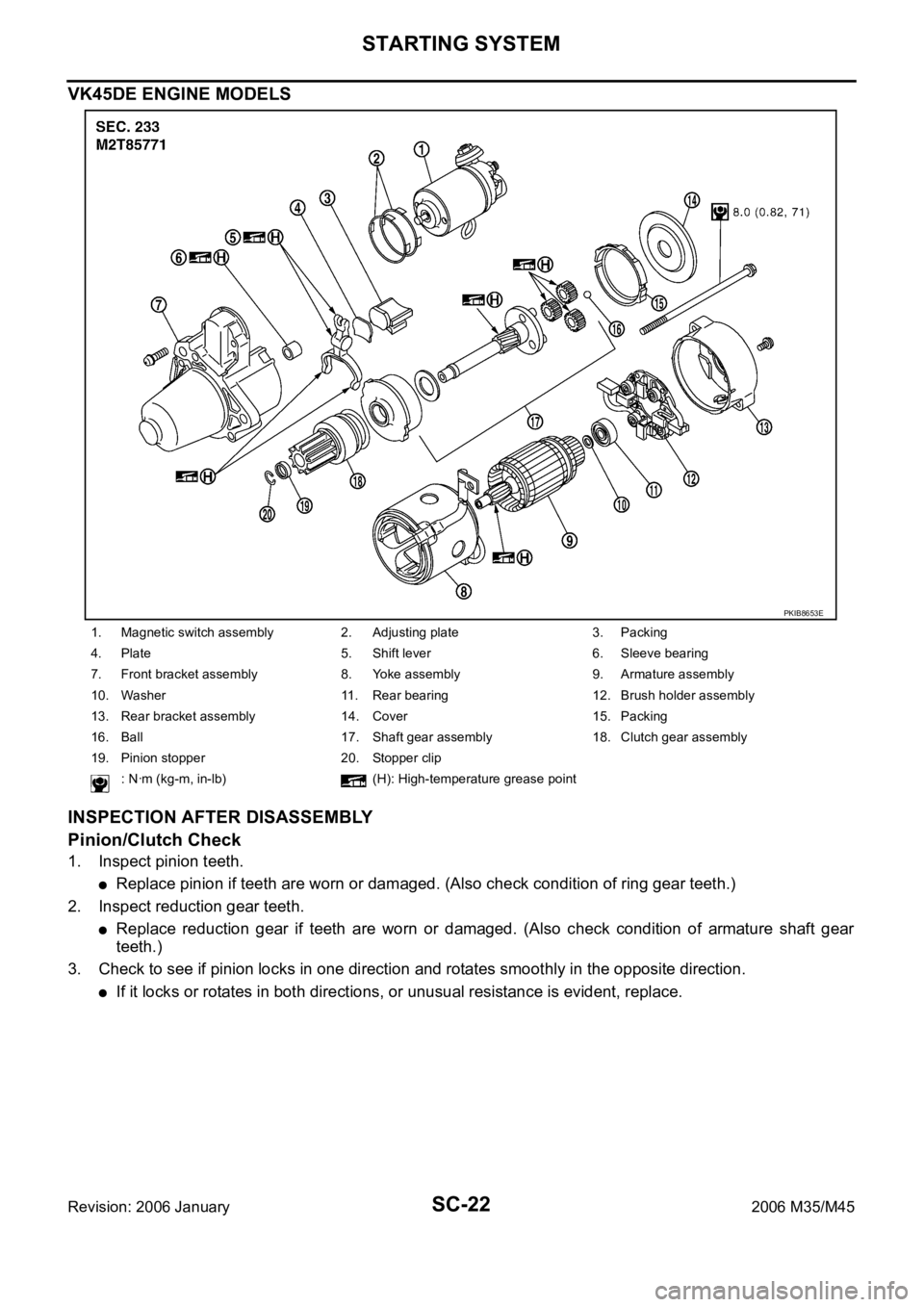
VK45DE ENGINE MODELS
INSPECTION AFTER DISASSEMBLY
Pinion/Clutch Check
1. Inspect pinion teeth.
Replace pinion if teeth are worn or damaged. (Also check condition of ring gear teeth.)
2. Inspect reduction gear teeth.
Replace reduction gear if teeth are worn or damaged. (Also check condition of armature shaft gear
teeth.)
3. Check to see if pinion locks in one direction and rotates smoothly in the opposite direction.
If it locks or rotates in both directions, or unusual resistance is evident, replace.
1. Magnetic switch assembly 2. Adjusting plate 3. Packing
4. Plate 5. Shift lever 6. Sleeve bearing
7. Front bracket assembly 8. Yoke assembly 9. Armature assembly
10. Washer 11. Rear bearing 12. Brush holder assembly
13. Rear bracket assembly 14. Cover 15. Packing
16. Ball 17. Shaft gear assembly 18. Clutch gear assembly
19. Pinion stopper 20. Stopper clip
: Nꞏm (kg-m, in-lb) (H): High-temperature grease point
PKIB8653E
Page 5188 of 5621

SQUEAK AND RATTLE TROUBLE DIAGNOSES
SE-7
C
D
E
F
G
H
J
K
L
MA
B
SE
Revision: 2006 January2006 M35/M45
INSULATOR (Light foam block)
80845-71L00: 30 mm (1.18 in) thick, 30
50 mm (1.181.97 in)
FELT CLOTHTAPE
Used to insulate where movement does not occur. Ideal for instrument panel applications.
68370-4B000: 15
25 mm (0.590.98 in) pad/68239-13E00: 5 mm (0.20 in) wide tape roll
The following materials, not found in the kit, can also be used to repair squeaks and rattles.
UHMW (TEFLON) TAPE
Insulates where slight movement is present. Ideal for instrument panel applications.
SILICONE GREASE
Used in place of UHMW tape that will be visible or not fit. Will only last a few months.
SILICONE SPRAY
Use when grease cannot be applied.
DUCT TAPE
Use to eliminate movement.
CONFIRM THE REPAIR
Confirm that the cause of a noise is repaired by test driving the vehicle. Operate the vehicle under the same
conditions as when the noise originally occurred. Refer to the notes on the Diagnostic Worksheet.
Generic Squeak and Rattle TroubleshootingNIS0025O
Refer to Table of Contents for specific component removal and installation information.
INSTRUMENT PANEL
Most incidents are caused by contact and movement between:
1. The cluster lid A and instrument panel
2. Acrylic lens and combination meter housing
3. Instrument panel to front pillar garnish
4. Instrument panel to windshield
5. Instrument panel mounting pins
6. Wiring harnesses behind the combination meter
7. A/C defroster duct and duct joint
These incidents can usually be located by tapping or moving the components to duplicate the noise or by
pressing on the components while driving to stop the noise. Most of these incidents can be repaired by apply-
ing felt cloth tape or silicon spray (in hard to reach areas). Urethane pads can be used to insulate wiring har-
ness.
CAUTION:
Do not use silicone spray to isolate a squeak or rattle. If you saturate the area with silicone, you will
not be able to recheck the repair.
CENTER CONSOLE
Components to pay attention to include:
1. Shifter assembly cover to finisher
2. A/C control unit and cluster lid C
3. Wiring harnesses behind audio and A/C control unit
The instrument panel repair and isolation procedures also apply to the center console.
DOORS
Pay attention to the:
1. Finisher and inner panel making a slapping noise
2. Inside handle escutcheon to door finisher
3. Wiring harnesses tapping
4. Door striker out of alignment causing a popping noise on starts and stops
Tapping or moving the components or pressing on them while driving to duplicate the conditions can isolate
many of these incidents. You can usually insulate the areas with felt cloth tape or insulator foam blocks from
the Nissan Squeak and Rattle Kit (J-43980) to repair the noise.
Page 5194 of 5621

AUTOMATIC DRIVE POSITIONER
SE-13
C
D
E
F
G
H
J
K
L
MA
B
SE
Revision: 2006 January2006 M35/M45
*: Door mirror operation starts with the start of seat sliding operation.
Storing Memory Procedure
1. Turn ignition switch to ON.
2. Shift A/T selector lever to P position.
3. Adjust position of driver seat, steering and mirror position.
4. Press set switch.
Indicator LED for which driver seat positions are already retained in memory is illuminated for 5 sec-
onds.
Indicator LED for which driver seat positions are not retained in memory is illuminated for 0.5 second.
5. Press memory switch for which driver seat positions are to be entered in memory for more than 0.5 sec-
ond within 5 seconds after pressing the set switch (during the indicator LED is illuminated).
To enter driver seat positions in blank memory, indicator LED will be illuminated for 5 seconds.
To modify driver seat positions, indicator LED will be turned OFF for 0.5 second then illuminated for 5
seconds.
6.
If you need setting of INTELLIGENT KEY INTERLOCK OPERATION, continue this procedure.
If you don't need setting of INTELLIGENT KEY INTERLOCK OPERATION, the procedure is finished.
Conform the operations of each part with the MEMORY OPERATION.
7. Press intelligent key unlock button within 5 seconds after pressing memory switch.
(While memory switch LED is illuminated.)
8. Conform the operations of each part with MEMORY OPERATION and INTELLIGENT KEY INTERLOCK
OPERATION.
NOTE:
Driving position is erased from the memory when battery cable is disconnected.
Order of priority Operated portion
1* Seat sliding
2 Steering telescopic
3 Steering wheel tilt
4 Seat reclining
5 Seat lifter (front)
6 Seat lifter (rear)
Page 5196 of 5621

AUTOMATIC DRIVE POSITIONER
SE-15
C
D
E
F
G
H
J
K
L
MA
B
SE
Revision: 2006 January2006 M35/M45
INTELLIGENT KEY INTERLOCK OPERATION
When pressing unlock button on Intelligent Key or request switch, the system performs memory operation,
exiting operation and entry operation.
Operation procedure
1. Press unlock button on Intelligent Key or request switch.
2. The system performs MEMORY OPERATION, and then performs EXITING OPERATION continually.
NOTE:
If the seat position is in memorized position before push unlock button, MEMORY OPEPATION dose not per-
form.
3. Turn ignition switch ON or close driver side door when ignition switch is in “ACC” position.
4. The system performs ENTRY OPERATION. (Seat and steering positions are moved to memorized posi-
tions. The memorize position is related to key ID.)
Operation Condition
If the following conditions are not satisfied, memory switch operation is not performed.
Ignition switch is in OFF position.
Driver side power seat switch and door mirror control switch are not operated.
Seat memory switch and set switch are not operated.
Output malfunction is not detected.
CAN and UART communications are normal.
A/T selector lever position is in P position.
Detention position switch malfunction is not detected.
[Detention position switch malfunction is sensed when detention switch remains OFF and vehicle speed is
higher than 7 km/h (4 MPH).]
Linking Intelligent Key to the Stored Memory Procedure
NOTE:
If ignition switch turns ON in the middle of memory operation, the system does not perform exiting opera-
tion after memory operation.
If ignition switch turns ON in the middle of exiting operation, entry operation starts at that time.
If entry / exiting operation is cancelled, perform memory operation only.
FAIL-SAFE MODE
If any of the parts move more than a period “T” without any switch operation, MEMORY OPERATION, EXIT-
ING OPERATION, ENTRY OPERATION, INTELLIGENT KEY INTERLOCK OPERATION and the malfunction
part of manual operations are not operated (output malfunction).
Canceling Fail-safe Mode
The mode is cancelled by either of the following operations.
When the selector lever is shifted to P position from any other position (detention switch is turned OFF).
Operated portion T
Seat slidingApprox. 0.1 sec.
Seat recliningApprox. 0.1 sec.
Seat lifter (front)Approx. 0.1 sec.
Seat lifter (rear)Approx. 0.1 sec.
Steering tiltApprox. 0.1 sec.
Page 5401 of 5621
SRS-40
SPIRAL CABLE
Revision: 2006 January2006 M35/M45
SPIRAL CABLEPFP:25554
Removal and InstallationNHS0009D
REMOVAL
CAUTION:
Before servicing, turn ignition switch OFF, disconnect both battery terminal and wait at least 3
minutes.
Do not use air tools or electric tools for servicing.
Do not disassemble the spiral cable.
Do not arrow oil, grease, detergent or water to come in contact with the spiral cable.
Do not make an impact to the spiral cable by dropping etc. Replace the spiral cable if it has been
dropped or sustained an impact.
1. Remove the air bag module. Refer to SRS-38, "
Removal and Installation" .
2. Remove the steering wheel. Refer to PS-12, "
Removal and Installation" .
3. Remove the column cover.
4. Remove the wiper washer switch, then remove light and turn signal switch from the spiral cable.
5. Remove the spiral cable.
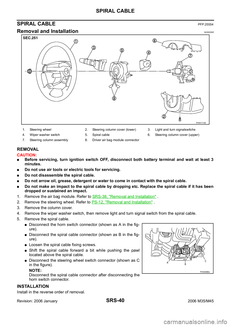
Disconnect the horn switch connector (shown as A in the fig-
ure).
Disconnect the spiral cable connector (shown as B in the fig-
ure).
Loosen the spiral cable fixing screws.
Shift the spiral cable forward a bit while pushing the pawl
located above the spiral cable.
Disconnect the steering wheel switch connector (shown as C
in the figure).
NOTE:
Disconnect the spiral cable connector after disconnecting the
horn switch connector.
INSTALLATION
Install in the reverse order of removal.
PHIA1112E
1. Steering wheel 2. Steering column cover (lower) 3. Light and turn signalswitchs
4. Wiper washer switch 5. Spiral cable 6. Steering column cover (upper)
7. Steering column assembly 8. Driver air bag module connector
PHIA0886J
Page 5475 of 5621
TF-10
AWD SYSTEM
Revision: 2006 January2006 M35/M45
AWD SYSTEMPFP:41650
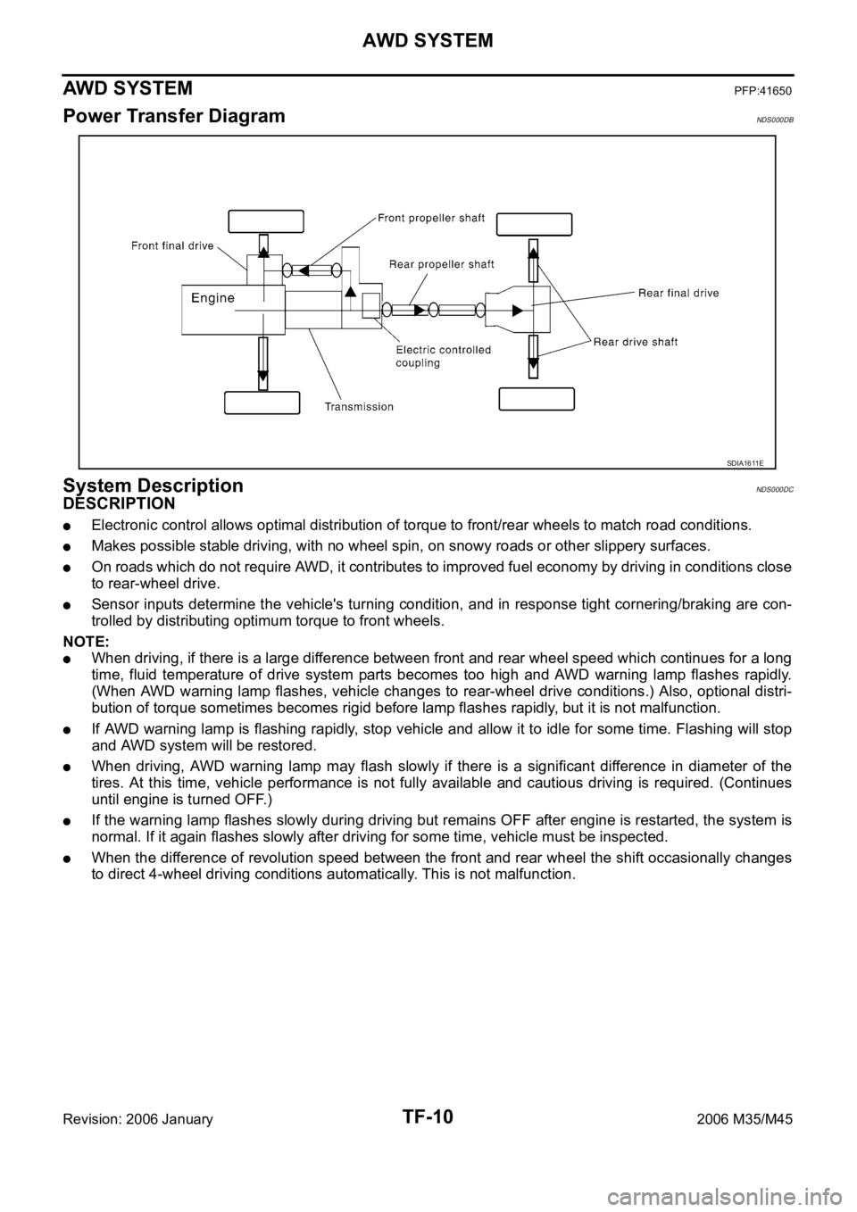
Power Transfer DiagramNDS000DB
System DescriptionNDS000DC
DESCRIPTION
Electronic control allows optimal distribution of torque to front/rear wheels to match road conditions.
Makes possible stable driving, with no wheel spin, on snowy roads or other slippery surfaces.
On roads which do not require AWD, it contributes to improved fuel economy by driving in conditions close
to rear-wheel drive.
Sensor inputs determine the vehicle's turning condition, and in response tight cornering/braking are con-
trolled by distributing optimum torque to front wheels.
NOTE:
When driving, if there is a large difference between front and rear wheel speed which continues for a long
time, fluid temperature of drive system parts becomes too high and AWD warning lamp flashes rapidly.
(When AWD warning lamp flashes, vehicle changes to rear-wheel drive conditions.) Also, optional distri-
bution of torque sometimes becomes rigid before lamp flashes rapidly, but it is not malfunction.
If AWD warning lamp is flashing rapidly, stop vehicle and allow it to idle for some time. Flashing will stop
and AWD system will be restored.
When driving, AWD warning lamp may flash slowly if there is a significant difference in diameter of the
tires. At this time, vehicle performance is not fully available and cautious driving is required. (Continues
until engine is turned OFF.)
If the warning lamp flashes slowly during driving but remains OFF after engine is restarted, the system is
normal. If it again flashes slowly after driving for some time, vehicle must be inspected.
When the difference of revolution speed between the front and rear wheel the shift occasionally changes
to direct 4-wheel driving conditions automatically. This is not malfunction.
SDIA1611E
Page 5477 of 5621
TF-12
AWD SYSTEM
Revision: 2006 January2006 M35/M45
AWD WARNING LAMP
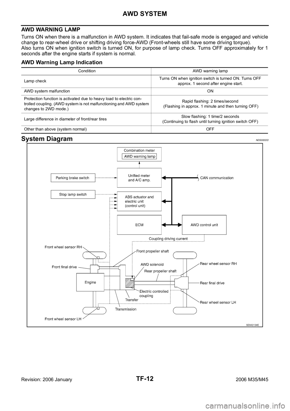
Turns ON when there is a malfunction in AWD system. It indicates that fail-safe mode is engaged and vehicle
change to rear-wheel drive or shifting driving force-AWD (Front-wheels still have some driving torque).
Also turns ON when ignition switch is turned ON, for purpose of lamp check. Turns OFF approximately for 1
seconds after the engine starts if system is normal.
AWD Warning Lamp Indication
System DiagramNDS000DD
Condition AWD warning lamp
Lamp checkTurns ON when ignition switch is turned ON. Turns OFF
approx. 1 second after engine start.
AWD system malfunctionON
Protection function is activated due to heavy load to electric con-
trolled coupling. (AWD system is not malfunctioning and AWD system
changes to 2WD mode.)Rapid flashing: 2 times/second
(Flashing in approx. 1 minute and then turning OFF)
Large difference in diameter of front/rear tiresSlow flashing: 1 time/2 seconds
(Continuing to flash until turning ignition switch OFF)
Other than above (system normal) OFF
SDIA3134E
Page 5479 of 5621
TF-14
TROUBLE DIAGNOSIS
Revision: 2006 January2006 M35/M45
TROUBLE DIAGNOSISPFP:00004
Fail-Safe FunctionNDS000DF
If any malfunction occurs in AWD electrical system, and control unit detects the malfunction, AWD warn-
ing lamp on combination meter turns ON to indicate system malfunction.
When AWD warning lamp is ON, vehicle changes to rear-wheel drive or shifting driving force-AWD (Front-
wheels still have some driving torque).
How to Perform Trouble DiagnosisNDS000DG
BASIC CONCEPT
To perform trouble diagnosis, it is the most important to have understanding about vehicle systems (con-
trol and mechanism) thoroughly.
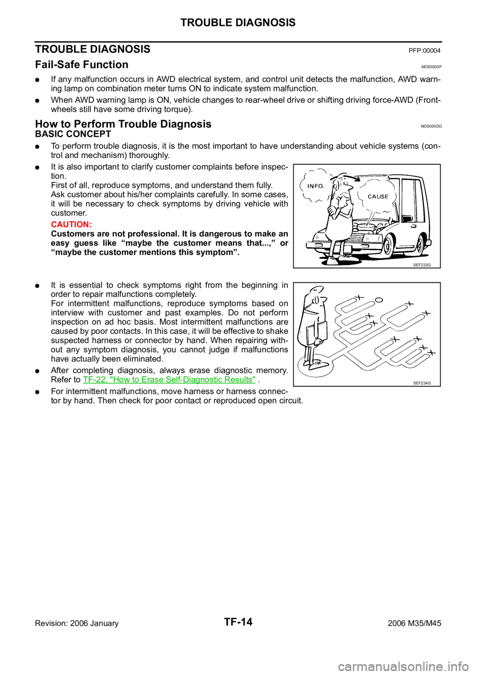
It is also important to clarify customer complaints before inspec-
tion.
First of all, reproduce symptoms, and understand them fully.
Ask customer about his/her complaints carefully. In some cases,
it will be necessary to check symptoms by driving vehicle with
customer.
CAUTION:
Customers are not professional. It is dangerous to make an
easy guess like “maybe the customer means that...,” or
“maybe the customer mentions this symptom”.
It is essential to check symptoms right from the beginning in
order to repair malfunctions completely.
For intermittent malfunctions, reproduce symptoms based on
interview with customer and past examples. Do not perform
inspection on ad hoc basis. Most intermittent malfunctions are
caused by poor contacts. In this case, it will be effective to shake
suspected harness or connector by hand. When repairing with-
out any symptom diagnosis, you cannot judge if malfunctions
have actually been eliminated.
After completing diagnosis, always erase diagnostic memory.
Refer to TF-22, "
How to Erase Self-Diagnostic Results" .
For intermittent malfunctions, move harness or harness connec-
tor by hand. Then check for poor contact or reproduced open circuit.
SEF233G
SEF234G