2006 INFINITI M35 heater
[x] Cancel search: heaterPage 4800 of 5621

ENGINE MAINTENANCE (VK45DE ENGINE)
MA-23
C
D
E
F
G
H
I
J
K
MA
B
MA
Revision: 2006 January2006 M35/M45
When draining all of engine coolant in the system, open water drain plugs on cylinder block. Refer
to EM-250, "
DISASSEMBLY" .
4. Remove reservoir tank as necessary, and drain engine coolant and clean reservoir tank before installing.
5. Check drained engine coolant for contaminants such as rust, corrosion or discoloration.
If contaminated, flush the engine cooling system. Refer to MA-24, "
FLUSHING COOLING SYSTEM" .
REFILLING ENGINE COOLANT
1. Install reservoir tank if removed, and radiator drain plug.
CAUTION:
Be sure to clean radiator drain plug and install with new O-ring.
If water drain plugs on cylinder block are removed, close and tighten them. Refer to EM-254,
"ASSEMBLY" .
2. Make sure that each hose clamp has been firmly tightened.
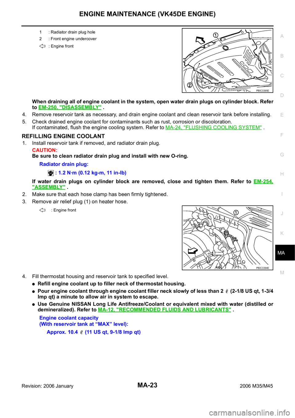
3. Remove air relief plug (1) on heater hose.
4. Fill thermostat housing and reservoir tank to specified level.
Refill engine coolant up to filler neck of thermostat housing.
Pour engine coolant through engine coolant filler neck slowly of less than 2 (2-1/8 US qt, 1-3/4
Imp qt) a minute to allow air in system to escape.
Use Genuine NISSAN Long Life Antifreeze/Coolant or equivalent mixed with water (distilled or
demineralized). Refer to MA-12, "
RECOMMENDED FLUIDS AND LUBRICANTS" .
1 : Radiator drain plug hole
2 : Front engine undercover
: Engine front
PBIC3395E
Radiator drain plug:
: 1.2 Nꞏm (0.12 kg-m, 11 in-lb)
: Engine front
PBIC3394E
Engine coolant capacity
(With reservoir tank at “MAX” level):
Approx. 10.4 (11 US qt, 9-1/8 Imp qt)
Page 4801 of 5621

MA-24
ENGINE MAINTENANCE (VK45DE ENGINE)
Revision: 2006 January2006 M35/M45
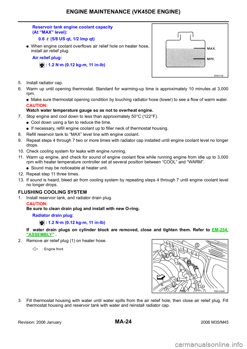
When engine coolant overflows air relief hole on heater hose,
install air relief plug.
5. Install radiator cap.
6. Warm up until opening thermostat. Standard for warming-up time is approximately 10 minutes at 3,000
rpm.
Make sure thermostat opening condition by touching radiator hose (lower) to see a flow of warm water.
CAUTION:
Watch water temperature gauge so as not to overheat engine.
7. Stop engine and cool down to less than approximately 50
C (122F).
Cool down using a fan to reduce the time.
If necessary, refill engine coolant up to filler neck of thermostat housing.
8. Refill reservoir tank to “MAX” level line with engine coolant.
9. Repeat steps 4 through 7 two or more times with radiator cap installed until engine coolant level no longer
drops.
10. Check cooling system for leaks with engine running.
11. Warm up engine, and check for sound of engine coolant flow while running engine from idle up to 3,000
rpm with heater temperature controller set at several position between “COOL” and “WARM”.
Sound may be noticeable at heater unit.
12. Repeat step 11 three times.
13. If sound is heard, bleed air from cooling system by repeating steps 4 through 7 until engine coolant level
no longer drops.
FLUSHING COOLING SYSTEM
1. Install reservoir tank, and radiator drain plug.
CAUTION:
Be sure to clean drain plug and install with new O-ring.
If water drain plugs on cylinder block are removed, close and tighten them. Refer to EM-254,
"ASSEMBLY" .
2. Remove air relief plug (1) on heater hose.
3. Fill thermostat housing with water until water spills from the air relief hole, then close air relief plug. Fill
thermostat housing and reservoir tank with water and reinstall radiator cap. Reservoir tank engine coolant capacity
(At “MAX” level):
0.6 (5/8 US qt, 1/2 lmp qt)
Air relief plug:
: 1.2 Nꞏm (0.12 kg-m, 11 in-lb)
SMA412B
Radiator drain plug:
: 1.2 Nꞏm (0.12 kg-m, 11 in-lb)
: Engine front
PBIC3394E
Page 4920 of 5621

HARNESS
PG-93
C
D
E
F
G
H
I
J
L
MA
B
PG
Revision: 2006 January2006 M35/M45
Wiring Diagram Codes (Cell Codes) NKS004ET
Use the chart below to find out what each wiring diagram code stands for.
Refer to the wiring diagram code in the alphabetical index to find the location (page number) of each wiring
diagram.
Code Section Wiring Diagram Name
A/C ATC Air Conditioner
AF1B1 EC Air Fuel Ratio Sensor 1 Bank 1
AF1B2 EC Air Fuel Ratio Sensor 1 Bank 2
AF1HB1 EC Air Fuel Ratio Sensor 1 Heater Bank 1
AF1HB2 EC Air Fuel Ratio Sensor 1 Heater Bank 2
AFS LT Adaptive Front Lighting System
APPS1 EC Accelerator Pedal Position Sensor
APPS2 EC Accelerator Pedal Position Sensor
APPS3 EC Accelerator Pedal Position Sensor
ASC/BS EC Automatic Speed Control Device (ASCD) Brake Switch
ASC/SW EC Automatic Speed Control Device (ASCD) Steering Switch
ASCBOF EC Automatic Speed Control Device (ASCD) Brake Switch
ASCIND EC Automatic Speed Control Device (ASCD) Indicator
AT/IND DI A/T Indicator Lamp
AUT/DP SE Automatic Drive Positioner
AUTO/L LT Automatic Light System
AV AV Audio and Visual System
AWD TF AWD Control System
BACK/L LT Back-Up Lamp
BRK/SW EC Brake Switch
C/SEAT SE Climate Controlled Seat
CAN AT CAN Communication Line
CAN EC CAN Communication Line
CAN LAN CAN System
CHARGE SC Charging System
CHIME DI Warning Chime
CIGAR WW Cigarette Lighter
CLOCK DI Clock
COMBSW LT Combination Switch
COMPAS DI Compass and Thermometer
COOL/F EC Cooling Fan Control
CUR/SE EC Battery Current Sensor
D/LOCK BL Power Door Lock
DEF GW Rear Window Defogger
DTRL LT Headlamp - with Daytime Light System
ECM/PW EC ECM Power Supply for Back-Up
ECTS EC Engine Coolant Temperature Sensor
ENG/ST BL Engine Start System
EPS STC Electric Controlled Power Steering System
ETC1 EC Electric Throttle Control Function
ETC2 EC Electric Throttle Control Motor Relay
Page 4921 of 5621

PG-94
HARNESS
Revision: 2006 January2006 M35/M45
ETC3 EC Electric Throttle Control Motor
F/FOG LT Front Fog Lamp
F/PUMP EC Fuel Pump
FPCM EC Fuel Pump Control Module
FTS AT A/T Fluid Temperature Sensor Circuit
FTTS EC Fuel Tank Temperature Sensor
FUELB1 EC Fuel Injection System Function (Bank 1)
FUELB2 EC Fuel Injection System Function (Bank 2)
H/LAMP LT Headlamp
HORN WW Horn
HSEAT SE Heated Seat
I/KEY BL Intelligent Key System
I/MIRR GW Inside Mirror (Auto Anti-Dazzling Mirror)
IATS EC Intake Air Temperature Sensor
ICC ACS Intelligent Cruise Control System
ICC/BS EC ICC Brake Switch
ICC/SW EC ICC Steering Switch
ICCBOF EC ICC Brake Switch
IGNSYS EC Ignition System
ILL LT Illumination
INJECT EC Injector
IVCB1 EC Intake Valve Timing Control Solenoid Valve Bank 1
IVCB2 EC Intake Valve Timing Control Solenoid Valve Bank 2
IVCSB1 EC Intake Valve Timing Control Position Sensor Bank 1
IVCSB2 EC Intake Valve Timing Control Position Sensor Bank 2
IVTB1 EC Intake Valve Timing Control System (Bank 1)
IVTB2 EC Intake Valve Timing Control System (Bank 2)
KS EC Knock Sensor
LDW DI Lane Departure Warning System
MAFS EC Mass Air Flow Sensor
MAIN AT Main Power Supply and Ground Circuit
MAIN EC Main Power Supply and Ground Circuit
METER DI Speedometer, Tachometer, Temp., Oil and Fuel Gauges
MIL/DL EC MIL & Data Link Connector
MIRROR GW Door Mirror
MMSW AT Manual Mode Switch
NATS BL Nissan Anti-Theft System
NONDTC AT Non-Detective Items
O2H2B1 EC Heated Oxygen Sensor 2 Heater Bank 1
O2H2B2 EC Heated Oxygen Sensor 2 Heater Bank 2
O2S2B1 EC Heated Oxygen Sensor 2 Bank 1
O2S2B2 EC Heated Oxygen Sensor 2 Bank 2
P/SCKT WW Power Socket
PDU PG Power Distribution Unit Code Section Wiring Diagram Name
Page 5165 of 5621

SC-28
CHARGING SYSTEM
Revision: 2006 January2006 M35/M45
Trouble Diagnoses with Battery/Starting/Charging System Tester (Charging)NKS003NP
NOTE:
To ensure a complete and thorough diagnosis, the battery, starter and alternator test segments must be done
as a set from start to finish.
Before starting, perform the preliminary inspection. Refer to SC-32, "
PRELIMINARY INSPECTION" .
1. Stop the operation of the power generation voltage variable control in either of the following procedures.
After selecting “ENGINE” of “SELECT SYSTEM” using CONSULT-II, set the DUTY value of “ALTERNA-
TOR DUTY” to 0% by selecting “ALTERNATOR DUTY” of “ACTIVE TEST”. Continue “ACTIVE TEST”
until the end of inspection. (When the DUTY value is 0 or 100%, the normal power generation is per-
formed according to the characteristic of the IC regulator of the alternator.)
Turn the ignition switch OFF, and disconnect the battery current sensor connector. [However, DTC
(P1550 - P1554) of the engine might remain. After finishing the inspection, connect the battery current
sensor connector and erase the self-diagnostic results history of the engine using CONSULT-II.]
2. Turn off all loads on the vehicle electrical system.
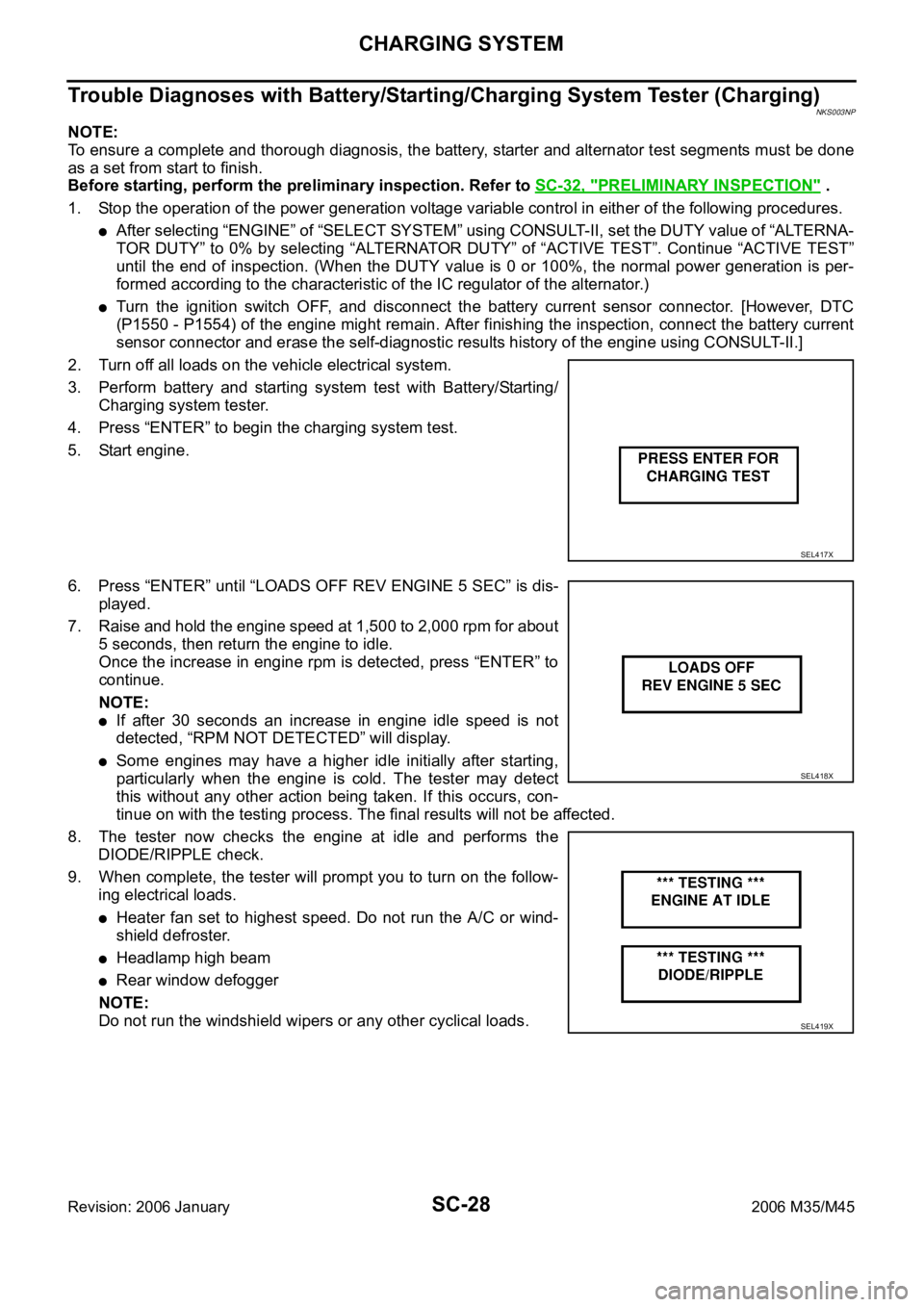
3. Perform battery and starting system test with Battery/Starting/
Charging system tester.
4. Press “ENTER” to begin the charging system test.
5. Start engine.
6. Press “ENTER” until “LOADS OFF REV ENGINE 5 SEC” is dis-
played.
7. Raise and hold the engine speed at 1,500 to 2,000 rpm for about
5 seconds, then return the engine to idle.
Once the increase in engine rpm is detected, press “ENTER” to
continue.
NOTE:
If after 30 seconds an increase in engine idle speed is not
detected, “RPM NOT DETECTED” will display.
Some engines may have a higher idle initially after starting,
particularly when the engine is cold. The tester may detect
this without any other action being taken. If this occurs, con-
tinue on with the testing process. The final results will not be affected.
8. The tester now checks the engine at idle and performs the
DIODE/RIPPLE check.
9. When complete, the tester will prompt you to turn on the follow-
ing electrical loads.
Heater fan set to highest speed. Do not run the A/C or wind-
shield defroster.
Headlamp high beam
Rear window defogger
NOTE:
Do not run the windshield wipers or any other cyclical loads.
SEL417X
SEL418X
SEL419X
Page 5183 of 5621

SE-2Revision: 2006 January2006 M35/M45 Reclining Switch Circuit Check ............................... 70
Lifting Switch (Front) Circuit Check ........................ 72
Lifting Switch (Rear) Circuit Check ......................... 74
Power Seat Switch Ground Circuit Check .............. 75
Telescopic Switch Circuit Check ............................. 76
Tilt Switch Circuit Check ......................................
... 78
Seat Memory and Set Switch Circuit Check ........... 80
Seat Memory Indicator Lamp Circuit Check ........... 81
Door Mirror Sensor Power Supply and Ground Cir-
cuit Check ............................................................... 83
A/T Device (Detention Switch) Circuit Check ......... 85
Front Door Switch (Driver Side) Circuit Check ....... 86
UART Communication Line Circuit Check .............. 87
Lumber Support Circuit Check ............................... 89
POWER SEAT(PASSENGER SIDE) ......................... 91
Component Parts and Harness Connector Location ... 91
Wiring Diagram—SEAT—/Passenger Side ............ 92
Terminals and Reference Values for BCM .............. 94
POWER SEAT(REAR) .............................................. 95
Component Parts and Harness Connector Location ... 95
System Description ................................................. 95
REAR POWER SEAT LH AND RH OPERATION ... 95
REAR SEAT RETREAT FUNCTION ................... 96
Schematic ............................................................... 97
Wiring Diagram—R/SEAT— ................................... 98
Terminals and Reference Values for Rear Seat Con-
trol Unit .................................................................102
Work Flow .............................................................103
Trouble Diagnoses Symptom Chart ......................103
Rear Power Seat Power Supply Circuit Inspection .103
Rear Seat Control Unit Power Supply and Ground
Circuit Inspection ..................................................104
Rear Seat Sliding Motor Circuit Inspection ...........105
Rear Power Seat Switch Circuit Inspection ..........106
Automatic Return Cancel Switch Circuit Inspection .108
Automatic Return Cancel Switch Inspection .........109
Rear Door Switch Circuit Inspection .....................110
Rear Seat Sliding Sensor Circuit Inspection ..........111
CLIMATE CONTROLLED SEAT .............................113
Component Parts and Harness Connector Location .113
System Description ...............................................113
Schematic .............................................................117
Wiring Diagram—C/SEAT— .................................118
Terminal and Reference Value for Climate Con-
trolled Seat Control Unit ......................................
.123
Work Flow .............................................................124
Preliminary Check ................................................124
Trouble Diagnoses Symptom Chart .....................
.125
Climate Controlled Seat Control Unit Power Supply
Circuit Check ........................................................126
Climate Controlled Seat Control Unit Power Supply
and Ground Circuit Inspection ..............................127
Climate Controlled Seat Switch Power Supply Cir-cuit Inspection .......................................................130
Climate Controlled Seat Switch Circuit Inspection .131
Climate Controlled Seat Switch Indicator Circuit
Inspection ..............................................................133
Seat Cushion Thermal Electric Device Circuit
Inspection ..............................................................135
Seatback Thermal Electric Device Circuit Inspec-
tion ........................................................................136
Seat Cushion Thermal Electric Device Sensor Cir-
cuit Inspection .......................................................137
Seatback Thermal Electric Device Sensor Circuit
Inspection ..............................................................139
Climate Controlled Seat Blower Motor Circuit
Inspection ..............................................................140
Climate Controlled Seat Control Unit Inspection ...142
HEATED SEAT ........................................................143
Component Parts and Harness Connector Location .143
System Description ...............................................143
Schematic .............................................................145
Wiring Diagram —HSEAT— .................................146
Terminals and Reference Values for Rear Seat Con-
trol Unit ..................................................................151
Work Flow .............................................................151
Trouble Diagnoses Symptom Chart ......................151
Rear Heated Seat Power Supply and Ground Circuit
Inspection ..............................................................152
Rear Seat Control Unit Power Supply and Ground
Circuit Inspection ..................................................153
Rear Heated Seat Switch Circuit Inspection .........155
Rear Heated Seat Indicator Power Supply Circuit
Inspection ..............................................................157
Rear Heated Seat Indicator Circuit Inspection ......158
Rear Heated Seat Circuit Inspection .....................160
Rear Seatback Heater Circuit Inspection ..............161
FRONT SEAT ..........................................................163
Driver's Seat Components ....................................163
Passenger's Seat Components .............................165
Removal and Installation .......................................167
REMOVAL ..........................................................167
INSTALLATION ..................................................167
Disassembly and Assembly ..................................168
SEATBACK ........................................................168
SEAT CUSHION ................................................169
CLIMATE CONTROLLED SEAT ........................171
REAR SEAT .............................................................172
Bench Seat Components ......................................172
Power Seat (Split Type) Components ...................174Removal and Installation .......................................176
BENCH SEAT ....................................................176
POWER SEAT ...................................................176
Disassembly and Assembly ..................................177
BENCH SEAT ....................................................177
POWER SEAT ...................................................179
Page 5323 of 5621

SE-142
CLIMATE CONTROLLED SEAT
Revision: 2006 January2006 M35/M45
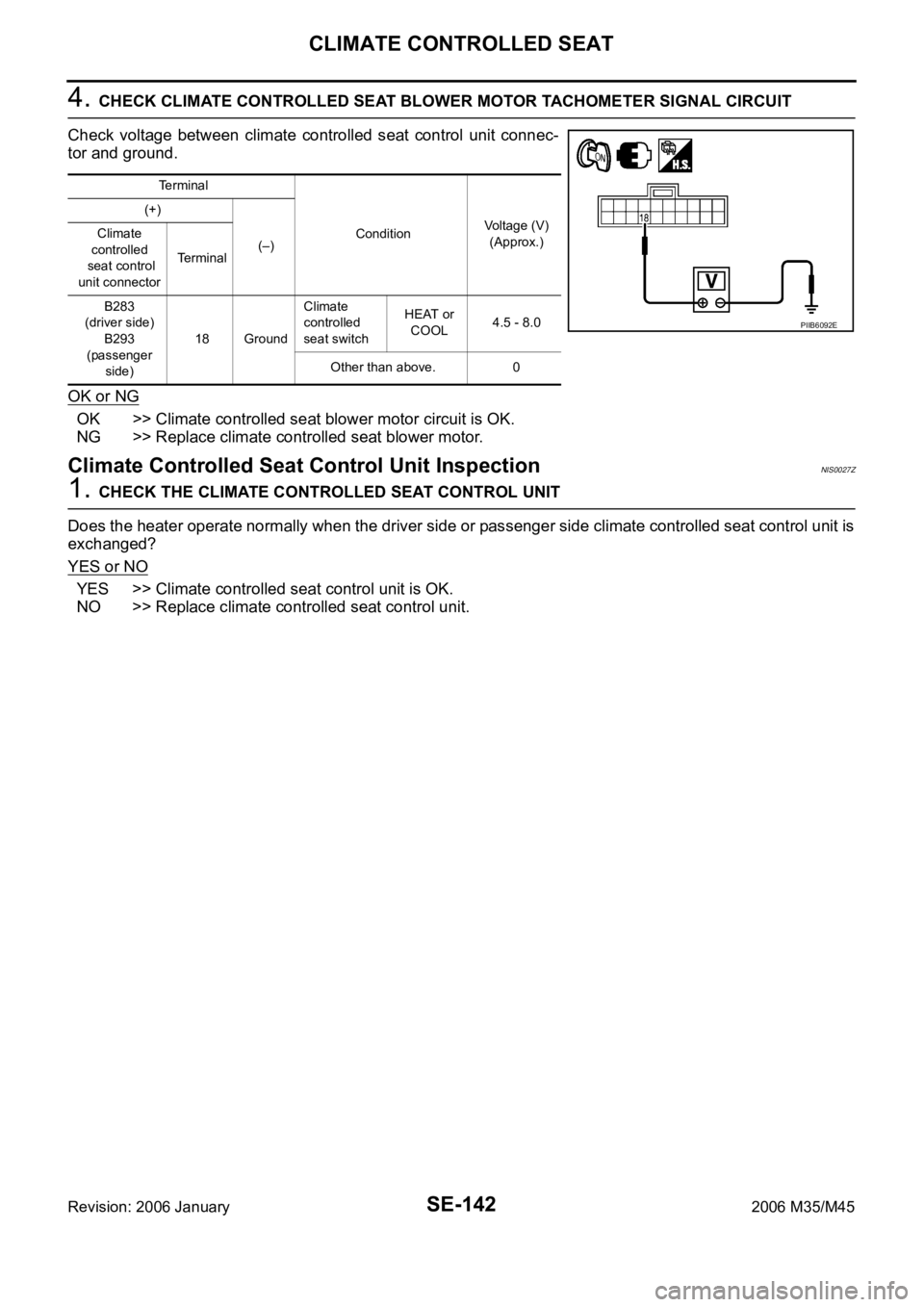
4. CHECK CLIMATE CONTROLLED SEAT BLOWER MOTOR TACHOMETER SIGNAL CIRCUIT
Check voltage between climate controlled seat control unit connec-
tor and ground.
OK or NG
OK >> Climate controlled seat blower motor circuit is OK.
NG >> Replace climate controlled seat blower motor.
Climate Controlled Seat Control Unit InspectionNIS0027Z
1. CHECK THE CLIMATE CONTROLLED SEAT CONTROL UNIT
Does the heater operate normally when the driver side or passenger side climate controlled seat control unit is
exchanged?
YES or NO
YES >> Climate controlled seat control unit is OK.
NO >> Replace climate controlled seat control unit.
Terminal
ConditionVoltage (V)
(Approx.) (+)
(–) Climate
controlled
seat control
unit connectorTerminal
B283
(driver side)
B293
(passenger
side)18 GroundClimate
controlled
seat switchHEAT or
COOL4.5 - 8.0
Other than above. 0
PIIB6092E
Page 5325 of 5621

SE-144
HEATED SEAT
Revision: 2006 January2006 M35/M45
When rear heated seat switch (LH, RH) is LOW position, ground is suppled
to rear seat control unit terminal 18,
through rear heated seat switch terminal 2,
through rear heated seat switch terminal 3,
through body grounds B5, B40 and B131
Then rear seat control unit recognizes that rear heated seat switch is LOW position.
When rear heated seat switch is LOW position, power is supplied
through rear seat control unit terminal 6,
through rear seat cushion heater terminal 2,
through rear seat cushion heater terminal 3,
to rear seatback heater terminal 1.
Then ground is suppled
to rear seatback heater terminal 2.
through body grounds B5, B40 and B131.
With power and ground supplied, rear heated seat is operated.
When rear heated seat switch is in LOW position, ground is supplied
to rear heated seat switch terminal 5,
through rear seat control unit terminal 14,
through rear seat control unit terminal 13,
through body grounds B5, B40 and B131.
With power and ground supplied, rear heated seat switch LOW position indicator is illuminated
When rear heated seat switch (LH, RH) is in HIGH position, ground is suppled
to rear seat control unit terminal 17,
through rear heated seat switch terminal 1,
through rear heated seat switch terminal 3,
through body grounds B5, B40 and B131
Then rear seat control unit recognizes that rear heated seat switch is in HIGH position.
When rear heated seat switch is in HIGH position, power is supplied
through rear seat control unit terminal 5,
through rear seat cushion heater terminal 1,
through rear seat cushion heater terminal 3,
to rear seatback heater terminal 1.
Then ground is suppled
to rear seatback heater terminal 2.
through body grounds B5, B40 and B131.
to rear seat cushion heater terminal 2,
through rear seat control unit terminal 6,
through rear seat control unit terminal 8,
through body grounds B5, B40 and B131.
With power and ground supplied, rear heated seat generates heat more than the time of LOW position.
When rear heated seat switch is in HIGH position, ground is supplied
to rear heated seat switch terminal 4,
through rear seat control unit terminal 9,
through rear seat control unit terminal 13,
through body grounds B5, B40 and B131.
With power and ground supplied rear heated seat switch HIGH position indicator is illuminated.