2006 INFINITI M35 wheel torque
[x] Cancel search: wheel torquePage 2434 of 5621
![INFINITI M35 2006 Factory Service Manual DTC P0011, P0021 IVT CONTROL
EC-891
[VK45DE]
C
D
E
F
G
H
I
J
K
L
MA
EC
Revision: 2006 January2006 M35/M45
DTC P0011, P0021 IVT CONTROLPFP:23796
DescriptionNBS005B9
SYSTEM DESCRIPTION
*: This signal is INFINITI M35 2006 Factory Service Manual DTC P0011, P0021 IVT CONTROL
EC-891
[VK45DE]
C
D
E
F
G
H
I
J
K
L
MA
EC
Revision: 2006 January2006 M35/M45
DTC P0011, P0021 IVT CONTROLPFP:23796
DescriptionNBS005B9
SYSTEM DESCRIPTION
*: This signal is](/manual-img/42/57023/w960_57023-2433.png)
DTC P0011, P0021 IVT CONTROL
EC-891
[VK45DE]
C
D
E
F
G
H
I
J
K
L
MA
EC
Revision: 2006 January2006 M35/M45
DTC P0011, P0021 IVT CONTROLPFP:23796
DescriptionNBS005B9
SYSTEM DESCRIPTION
*: This signal is sent to the ECM through CAN communication line
This mechanism hydraulically controls cam phases continuously with the fixed operating angle of the intake
valve.
The ECM receives signals such as crankshaft position, camshaft position, engine speed, and engine coolant
temperature. Then, the ECM sends ON/OFF pulse duty signals to the intake valve timing (IVT) control sole-
noid valve depending on driving status. This makes it possible to control the shut/open timing of the intake
valve to increase engine torque in low/mid speed range and output in high-speed range.
COMPONENT INSPECTION
Intake Valve Timing Control Solenoid Valve
Intake Valve Timing (IVT) control solenoid valve is activated by ON/
OFF pulse duty (ratio) signals from the ECM.
The IVT control solenoid valve changes the oil amount and direction
of flow through intake valve timing control unit or stops oil flow.
The longer pulse width advances valve angle.
The shorter pulse width retards valve angle.
When ON and OFF pulse widths become equal, the solenoid valve
stops oil pressure flow to fix the intake valve angle at the control
position.
Sensor Input signal to ECM function ECM Actuator
Crankshaft position sensor (POS)
Camshaft position sensor (PHASE)Engine speed
Intake valve
timing controlIntake valve timing control
solenoid valve Intake valve timing control position sensor Intake valve timing signal
Engine coolant temperature sensor Engine coolant temperature
Wheel sensor* Vehicle speed
PBIB3276E
PBIB1842E
Page 3362 of 5621
![INFINITI M35 2006 Factory Service Manual PREPARATION
FAX-3
C
E
F
G
H
I
J
K
L
MA
B
FA X
Revision: 2006 January2006 M35/M45
PREPARATIONPFP:00002
Special Service Tools [SST]NDS000FC
The actual shapes of Kent-Moore tools may differ from those of INFINITI M35 2006 Factory Service Manual PREPARATION
FAX-3
C
E
F
G
H
I
J
K
L
MA
B
FA X
Revision: 2006 January2006 M35/M45
PREPARATIONPFP:00002
Special Service Tools [SST]NDS000FC
The actual shapes of Kent-Moore tools may differ from those of](/manual-img/42/57023/w960_57023-3361.png)
PREPARATION
FAX-3
C
E
F
G
H
I
J
K
L
MA
B
FA X
Revision: 2006 January2006 M35/M45
PREPARATIONPFP:00002
Special Service Tools [SST]NDS000FC
The actual shapes of Kent-Moore tools may differ from those of special service tools illustrated here.
Commercial Service ToolsNDS000FD
Tool number
(Kent-Moore No.)
Tool nameDescription
KV40107300
(–)
Boot band crimping toolInstalling boot band
KV40107500
(–)
Drive shaft attachmentRemoving drive shaft
KV38107900
(–)
Protector
a: 32 mm (1.26 in) dia.Installing drive shaft
KV38100500
(–)
Drift
a: 80 mm (3.15 in) dia.
b: 60 mm (2.36 in) dia.Installing drive shaft plug
KV38102200
(–)
Drift
a: 90 mm (3.54 in) dia.
b: 31 mm (1.22 in) dia.Installing drive shaft plug
ZZA1229D
ZZA1230D
ZZA0835D
ZZA0701D
ZZA0920D
Tool name Description
Power tool
Removing wheel nuts
Removing torque member fixing bolts
Removing hub lock nut
PBIC0190E
Page 3364 of 5621
FRONT WHEEL HUB AND KNUCKLE
FAX-5
C
E
F
G
H
I
J
K
L
MA
B
FA X
Revision: 2006 January2006 M35/M45
FRONT WHEEL HUB AND KNUCKLEPFP:40202
On-Vehicle Inspection and ServiceNDS000FF
Make sure that the mounting conditions (looseness, backlash) of each component and component conditions
(wear, damage) are normal.
WHEEL BEARING INSPECTION
Move wheel hub and bearing assembly in the axial direction by hand. Make sure there is no looseness of
wheel bearing.
Rotate wheel hub and make sure that is no unusual noise or other irregular conditions. If there is any of
irregular conditions, replace wheel hub and bearing assembly
Removal and InstallationNDS000FG
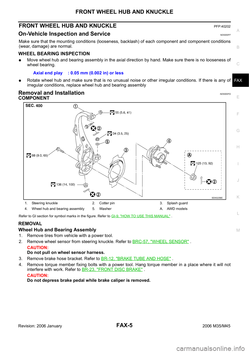
COMPONENT
Refer to GI section for symbol marks in the figure. Refer to GI-9, "HOW TO USE THIS MANUAL" .
REMOVAL
Wheel Hub and Bearing Assembly
1. Remove tires from vehicle with a power tool.
2. Remove wheel sensor from steering knuckle. Refer to BRC-57, "
WHEEL SENSOR" .
CAUTION:
Do not pull on wheel sensor harness.
3. Remove brake hose bracket. Refer to BR-12, "
BRAKE TUBE AND HOSE" .
4. Remove torque member fixing bolts with a power tool. Hang torque member in a place where it will not
interfere with work. Refer to BR-23, "
FRONT DISC BRAKE" .
CAUTION:
Do not depress brake pedal while brake caliper is removed.Axial end play : 0.05 mm (0.002 in) or less
1. Steering knuckle 2. Cotter pin 3. Splash guard
4. Wheel hub and bearing assembly 5. Washer A. AWD models
SDIA3256E
Page 3365 of 5621
FAX-6
FRONT WHEEL HUB AND KNUCKLE
Revision: 2006 January2006 M35/M45
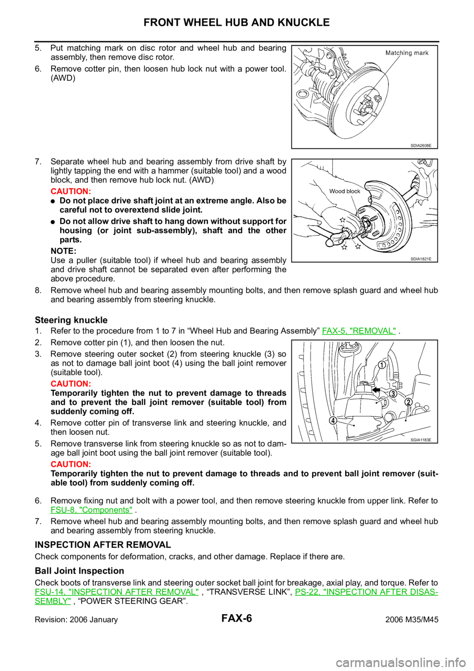
5. Put matching mark on disc rotor and wheel hub and bearing
assembly, then remove disc rotor.
6. Remove cotter pin, then loosen hub lock nut with a power tool.
(AWD)
7. Separate wheel hub and bearing assembly from drive shaft by
lightly tapping the end with a hammer (suitable tool) and a wood
block, and then remove hub lock nut. (AWD)
CAUTION:
Do not place drive shaft joint at an extreme angle. Also be
careful not to overextend slide joint.
Do not allow drive shaft to hang down without support for
housing (or joint sub-assembly), shaft and the other
parts.
NOTE:
Use a puller (suitable tool) if wheel hub and bearing assembly
and drive shaft cannot be separated even after performing the
above procedure.
8. Remove wheel hub and bearing assembly mounting bolts, and then remove splash guard and wheel hub
and bearing assembly from steering knuckle.
Steering knuckle
1. Refer to the procedure from 1 to 7 in “Wheel Hub and Bearing Assembly” FA X - 5 , "REMOVAL" .
2. Remove cotter pin (1), and then loosen the nut.
3. Remove steering outer socket (2) from steering knuckle (3) so
as not to damage ball joint boot (4) using the ball joint remover
(suitable tool).
CAUTION:
Temporarily tighten the nut to prevent damage to threads
and to prevent the ball joint remover (suitable tool) from
suddenly coming off.
4. Remove cotter pin of transverse link and steering knuckle, and
then loosen nut.
5. Remove transverse link from steering knuckle so as not to dam-
age ball joint boot using the ball joint remover (suitable tool).
CAUTION:
Temporarily tighten the nut to prevent damage to threads and to prevent ball joint remover (suit-
able tool) from suddenly coming off.
6. Remove fixing nut and bolt with a power tool, and then remove steering knuckle from upper link. Refer to
FSU-8, "
Components" .
7. Remove wheel hub and bearing assembly mounting bolts, and then remove splash guard and wheel hub
and bearing assembly from steering knuckle.
INSPECTION AFTER REMOVAL
Check components for deformation, cracks, and other damage. Replace if there are.
Ball Joint Inspection
Check boots of transverse link and steering outer socket ball joint for breakage, axial play, and torque. Refer to
FSU-14, "
INSPECTION AFTER REMOVAL" , “TRANSVERSE LINK”, PS-22, "INSPECTION AFTER DISAS-
SEMBLY" , “POWER STEERING GEAR”.
SDIA2608E
SDIA1821E
SGIA1183E
Page 3366 of 5621
FRONT WHEEL HUB AND KNUCKLE
FAX-7
C
E
F
G
H
I
J
K
L
MA
B
FA X
Revision: 2006 January2006 M35/M45
INSTALLATION
Installation is the reverse order of the removal. For tightening torque, refer to FAX-5, "COMPONENT" .
Perform the final tightening of each of parts under unladen conditions, which were removed when remov-
ing wheel hub and bearing assembly and steering knuckle. Check the wheel alignment. Refer to FSU-6,
"Wheel Alignment Inspection" (2WD), FSU-23, "Wheel Alignment Inspection" (AWD).
Adjust neutral position of steering angle sensor after checking the wheel alignment. Refer to BRC-6,
"Adjustment of Steering Angle Sensor Neutral Position" .
Check wheel sensor harness for proper connection. Refer to BRC-57, "WHEEL SENSOR" .
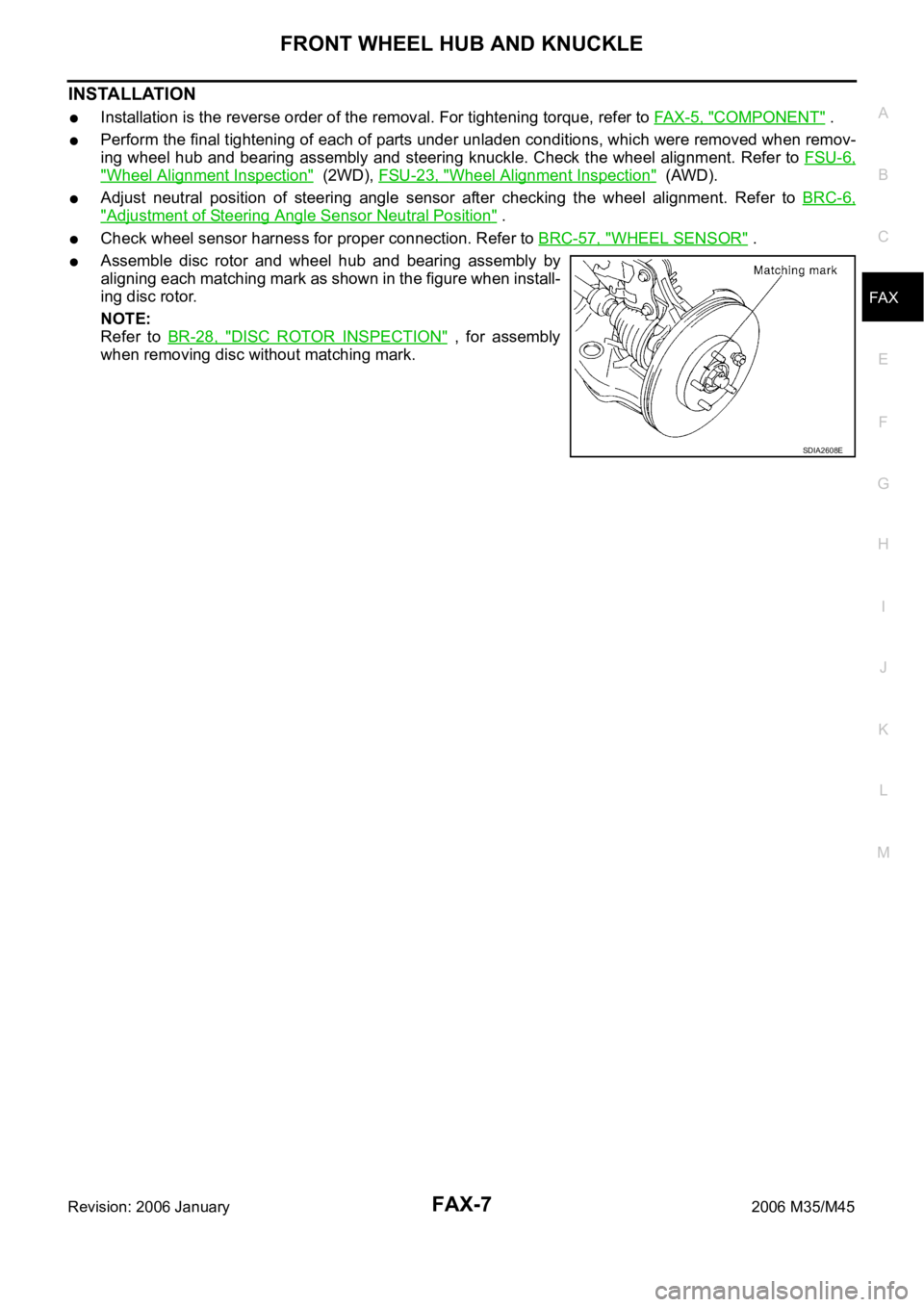
Assemble disc rotor and wheel hub and bearing assembly by
aligning each matching mark as shown in the figure when install-
ing disc rotor.
NOTE:
Refer to BR-28, "
DISC ROTOR INSPECTION" , for assembly
when removing disc without matching mark.
SDIA2608E
Page 3367 of 5621
FAX-8
FRONT DRIVE SHAFT
Revision: 2006 January2006 M35/M45
FRONT DRIVE SHAFTPFP:39100
On-Vehicle Inspection and ServiceNDS000FH
Check drive shaft mounting point and joint for looseness and other damage.
Check boot for cracks and other damage.
CAUTION:
Replace entire drive shaft assembly when noise or vibration occur from drive shaft.
DRIVE SHAFT BOOT REPLACEMENT
1. Remove tires from vehicle with a power tool.
2. Remove wheel sensor from steering knuckle. Refer to BRC-57, "
WHEEL SENSOR" .
CAUTION:
Do not pull on wheel sensor harness.
3. Remove brake hose bracket. Refer to BR-12, "
BRAKE TUBE AND HOSE" .
4. Remove torque menber fixing bolts with a power tool. Hang torque menber in a place where it will not
interfere with work. Refer to BR-23, "
FRONT DISC BRAKE" .
NOTE:
Do not depress brake pedal while brake caliper is removed.
5. Remove disc rotor. Refer to FA X - 5 , "
Removal and Installation" .
6. Remove cotter pin, then loosen hub lock nut with a power tool.
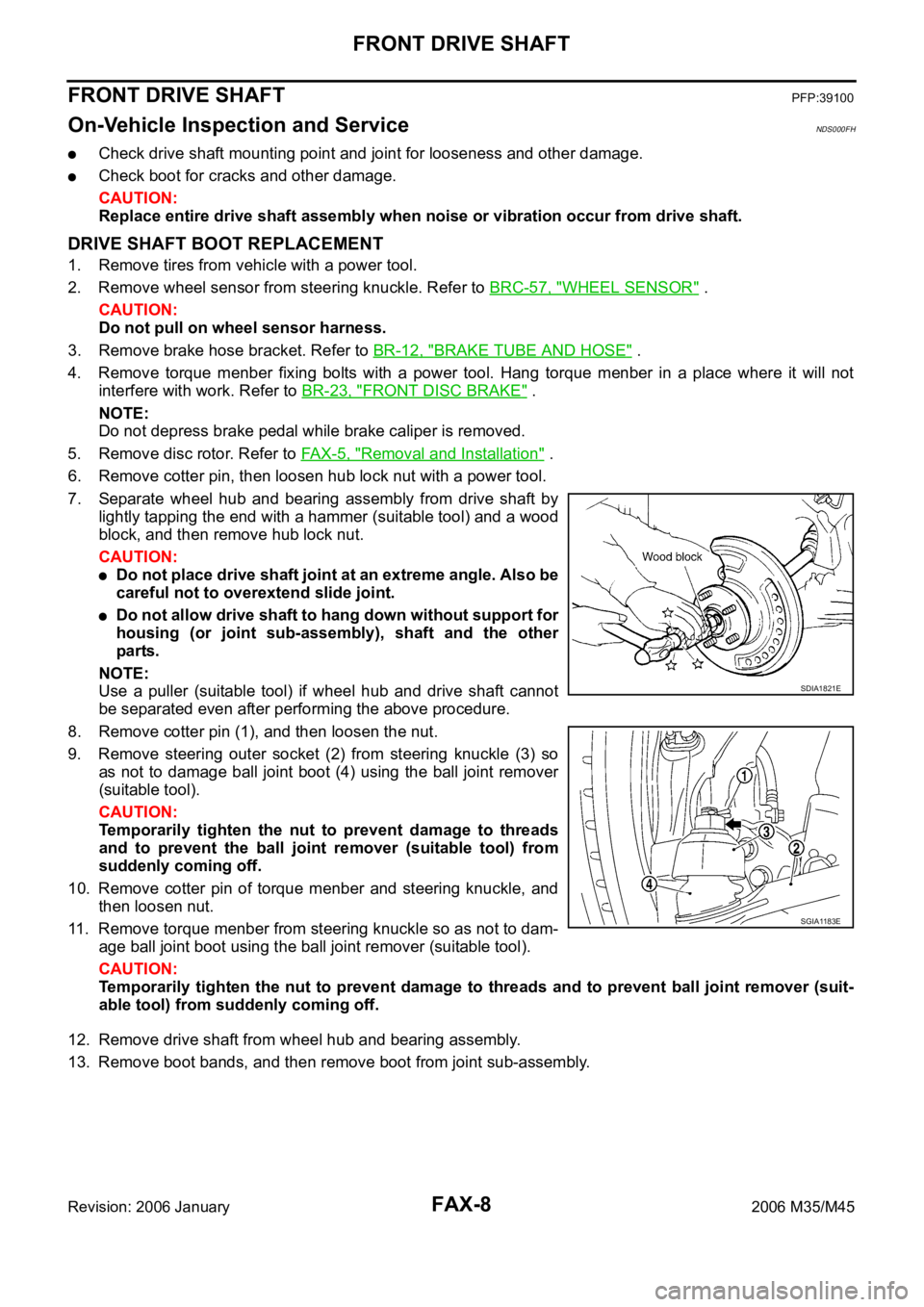
7. Separate wheel hub and bearing assembly from drive shaft by
lightly tapping the end with a hammer (suitable tool) and a wood
block, and then remove hub lock nut.
CAUTION:
Do not place drive shaft joint at an extreme angle. Also be
careful not to overextend slide joint.
Do not allow drive shaft to hang down without support for
housing (or joint sub-assembly), shaft and the other
parts.
NOTE:
Use a puller (suitable tool) if wheel hub and drive shaft cannot
be separated even after performing the above procedure.
8. Remove cotter pin (1), and then loosen the nut.
9. Remove steering outer socket (2) from steering knuckle (3) so
as not to damage ball joint boot (4) using the ball joint remover
(suitable tool).
CAUTION:
Temporarily tighten the nut to prevent damage to threads
and to prevent the ball joint remover (suitable tool) from
suddenly coming off.
10. Remove cotter pin of torque menber and steering knuckle, and
then loosen nut.
11. Remove torque menber from steering knuckle so as not to dam-
age ball joint boot using the ball joint remover (suitable tool).
CAUTION:
Temporarily tighten the nut to prevent damage to threads and to prevent ball joint remover (suit-
able tool) from suddenly coming off.
12. Remove drive shaft from wheel hub and bearing assembly.
13. Remove boot bands, and then remove boot from joint sub-assembly.
SDIA1821E
SGIA1183E
Page 3369 of 5621
FAX-10
FRONT DRIVE SHAFT
Revision: 2006 January2006 M35/M45
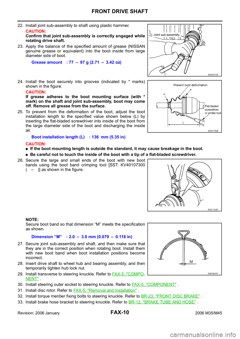
22. Install joint sub-assembly to shaft using plastic hammer.
CAUTION:
Confirm that joint sub-assembly is correctly engaged while
rotating drive shaft.
23. Apply the balance of the specified amount of grease (NISSAN
genuine grease or equivalent) into the boot inside from large
diameter side of boot.
24. Install the boot securely into grooves (indicated by * marks)
shown in the figure.
CAUTION:
If grease adheres to the boot mounting surface (with *
mark) on the shaft and joint sub-assembly, boot may come
off. Remove all grease from the surface.
25. To prevent from the deformation of the boot, adjust the boot
installation length to the specified value shown below (L) by
inserting the flat-bladed screwdriver into inside of the boot from
the large diameter side of the boot and discharging the inside
air.
CAUTION:
If the boot mounting length is outside the standard, it may cause breakage in the boot.
Be careful not to touch the inside of the boot with a tip of a flat-bladed screwdriver.
26. Secure the large and small ends of the boot with new boot
bands using the boot band crimping tool [SST: KV40107300
( – )] as shown in the figure.
NOTE:
Secure boot band so that dimension “M” meets the specification
as shown.
27. Secure joint sub-assembly and shaft, and then make sure that
they are in the correct position when rotating boot. Install them
with new boot band when boot installation positions become
incorrect.
28. Insert drive shaft to wheel hub and bearing assembly, and then
temporarily tighten hub lock nut.
29. Install transverse to steering knuckle. Refer to FAX-5, "
COMPO-
NENT" .
30. Install steering outer socket to steering knuckle. Refer to FA X - 5 , "
COMPONENT" .
31. Install disc rotor. Refer to FA X - 5 , "
Removal and Installation" .
32. Install torque menber fixing bolts to steering knuckle. Refer to BR-23, "
FRONT DISC BRAKE" .
33. Install brake hose bracket to steering knuckle. Refer to BR-12, "
BRAKE TUBE AND HOSE" . Grease amount : 77 – 97 g (2.71 – 3.42 oz)
SDIA2372E
Boot installation length (L) : 136 mm (5.35 in)
SDIA1760E
RAC1133D
Dimension “M” : 2.0 – 3.0 mm (0.079 – 0.118 in)
DSF0047D
Page 3370 of 5621
FRONT DRIVE SHAFT
FAX-11
C
E
F
G
H
I
J
K
L
MA
B
FA X
Revision: 2006 January2006 M35/M45
34. Install wheel sensor to steering knuckle. Refer to BRC-57, "WHEEL SENSOR" .
35. Tighten the hub lock nut to the specified torque. Refer to FA X - 5 , "
COMPONENT" .
36. Install cotter pin.
37. Install tires to vehicle.
Removal and InstallationNDS000FI
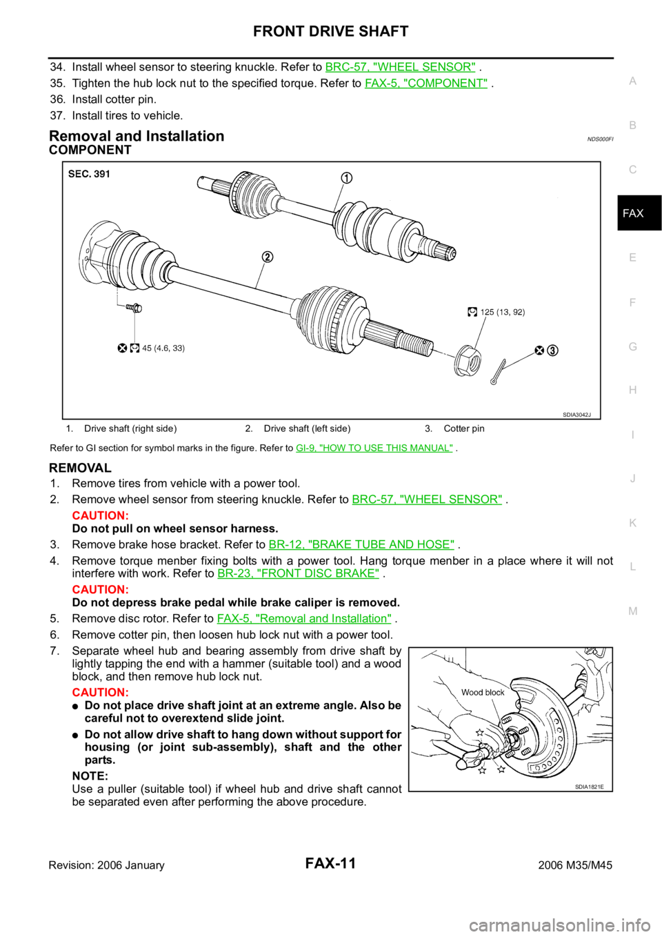
COMPONENT
Refer to GI section for symbol marks in the figure. Refer to GI-9, "HOW TO USE THIS MANUAL" .
REMOVAL
1. Remove tires from vehicle with a power tool.
2. Remove wheel sensor from steering knuckle. Refer to BRC-57, "
WHEEL SENSOR" .
CAUTION:
Do not pull on wheel sensor harness.
3. Remove brake hose bracket. Refer to BR-12, "
BRAKE TUBE AND HOSE" .
4. Remove torque menber fixing bolts with a power tool. Hang torque menber in a place where it will not
interfere with work. Refer to BR-23, "
FRONT DISC BRAKE" .
CAUTION:
Do not depress brake pedal while brake caliper is removed.
5. Remove disc rotor. Refer to FAX-5, "
Removal and Installation" .
6. Remove cotter pin, then loosen hub lock nut with a power tool.
7. Separate wheel hub and bearing assembly from drive shaft by
lightly tapping the end with a hammer (suitable tool) and a wood
block, and then remove hub lock nut.
CAUTION:
Do not place drive shaft joint at an extreme angle. Also be
careful not to overextend slide joint.
Do not allow drive shaft to hang down without support for
housing (or joint sub-assembly), shaft and the other
parts.
NOTE:
Use a puller (suitable tool) if wheel hub and drive shaft cannot
be separated even after performing the above procedure.
1. Drive shaft (right side) 2. Drive shaft (left side) 3. Cotter pin
SDIA3042J
SDIA1821E