2006 INFINITI M35 tires
[x] Cancel search: tiresPage 858 of 5621
![INFINITI M35 2006 Factory Service Manual DIAGNOSIS SYSTEM
AV-237
[WITH MOBILE ENTERTAINMENT SYSTEM]
C
D
E
F
G
H
I
J
L
MA
B
AV
Revision: 2006 January2006 M35/M45
NAVIGATION
Steering Angle Adjustment
The steering angle output value detected wi INFINITI M35 2006 Factory Service Manual DIAGNOSIS SYSTEM
AV-237
[WITH MOBILE ENTERTAINMENT SYSTEM]
C
D
E
F
G
H
I
J
L
MA
B
AV
Revision: 2006 January2006 M35/M45
NAVIGATION
Steering Angle Adjustment
The steering angle output value detected wi](/manual-img/42/57023/w960_57023-857.png)
DIAGNOSIS SYSTEM
AV-237
[WITH MOBILE ENTERTAINMENT SYSTEM]
C
D
E
F
G
H
I
J
L
MA
B
AV
Revision: 2006 January2006 M35/M45
NAVIGATION
Steering Angle Adjustment
The steering angle output value detected with the gyroscope can be
adjusted.
Speed Calibration
Usually the automatic distance correction function adjusts the mal-
function in distance caused by the tires wearing down or the tire
pressure change. If prompt adjustment is necessary when the tire
chains are installed etc., perform this procedure.
ERROR HISTORY
The diagnostic results of “Self-diagnosis” determine if any malfunction occurred between selecting “Self-diag-
nosis” and displaying “Self-diagnostic Results”.
If an error occurred before the ignition switch was turned ON and does not occur again until “Self-diagnosis” is
completed, the trouble diagnosis result will be judged normal. Therefore, errors in the past which cannot be
found by “Self-diagnosis”, must be found by checking the “Error record”.
The error history shows the error occurrence frequency in past. The frequency of occurrence is displayed by 2
types: the count down type and the count up type. Select either type according to the error item.
In “Error History” of models with NAVI, time and place that the selected error last occurred are displayed. Be
careful about the following.
If there is a malfunction with the GPS antenna circuit board in the NAVI control unit, the correct date of
occurrence may not be able to be displayed.
Place of the error occurrence is represented by the position of the current location mark at the time an
error occurred. If current location mark has deviated from the correct position, then the place of the error
occurrence cannot be located correctly.
Transition Screen
Without NAVI
SKIB3684E
SKIB3685E
SKIB3665E
Page 899 of 5621
![INFINITI M35 2006 Factory Service Manual AV-278
[WITH MOBILE ENTERTAINMENT SYSTEM]
TROUBLE DIAGNOSIS
Revision: 2006 January2006 M35/M45
MAP DVD-ROM
ROUTE CALCULATION AND VISUAL GUIDANCE
The location of vehicle icon is mis-
aligned from the a INFINITI M35 2006 Factory Service Manual AV-278
[WITH MOBILE ENTERTAINMENT SYSTEM]
TROUBLE DIAGNOSIS
Revision: 2006 January2006 M35/M45
MAP DVD-ROM
ROUTE CALCULATION AND VISUAL GUIDANCE
The location of vehicle icon is mis-
aligned from the a](/manual-img/42/57023/w960_57023-898.png)
AV-278
[WITH MOBILE ENTERTAINMENT SYSTEM]
TROUBLE DIAGNOSIS
Revision: 2006 January2006 M35/M45
MAP DVD-ROM
ROUTE CALCULATION AND VISUAL GUIDANCE
The location of vehicle icon is mis-
aligned from the actual position.When using tire chains or replacing the tires, speed
calculations based on the speed sensor may be
incorrect.Drive the vehicle for a while [at approxi-
mately 30km/h (19 MPH) for about 30
minutes] to automatically correct the vehi-
cle icon position.
If this does not correct the vehicle icon
position, contact an INFINITI dealer.
The map data has mistake or is incomplete (the
vehicle icon position is always misaligned in the
same area).Updated road information will be included
in the next version of the map DVD-ROM. Symptom Possible cause Possible solution
Symptom Possible cause Possible solution
The message “Error” appears. Map DVD-ROM is dirty or partially damaged.Check the DVD-ROM and wipe it clean
with a soft cloth.
If there is any damage, replace the DVD-
ROM.
Symptom Possible cause Possible solution
In the auto reroute calculation,
waypoints are not included.Waypoints already passed are not included in the
auto reroute calculation.In case of going to that waypoints again,
edit the route.
Route information is not displayed.Route calculation has not yet been performed.Set the destination and perform route cal-
culation.
The vehicle is not driven on the suggested route. Drive on the suggested route.
Route guidance is set to off. Turn on route guidance.
Route information is not provided for narrow streets
(roads displayed in gray).This is not a malfunction.
The auto reroute calculation (or
detour calculation) suggests the
same route as the one previously
suggested. Route calculation took priority conditions into con-
sideration, but the same route was calculated. This is not a malfunction.
A waypoint cannot be added.Five waypoints are already set on the route, includ-
ing ones that already passed.A maximum of 5 waypoints can be set on
the route. In case of going to 6 or more
waypoints, perform route calculations mul-
tiple times as necessary.
The suggested route is not dis-
played.Roads near the destination cannot be calculated.Reset the destination to a main or ordinary
road, and recalculate the route.
The starting point and destination are too close. Set a more distant destination.
The starting point and destination are too far away.Divide the way by selecting one or two
intermediate destinations, and perform
route calculations multiple times.
There are time restricted roads (by day of week, by
time) near the current vehicle location or destina-
tion.Set “Use Time Restricted Roads” to off.
A part of the route is not displayed.The suggested route includes narrow streets (roads
displayed in gray).This is not a malfunction.
The part of the route already
passed is deleted.A route is managed by sections between way-
points. If you passed the first waypoint, the section
between the starting point and the waypoint is
deleted. (It may not be deleted depending on the
area.)This is not a malfunction.
Page 903 of 5621
![INFINITI M35 2006 Factory Service Manual AV-282
[WITH MOBILE ENTERTAINMENT SYSTEM]
TROUBLE DIAGNOSIS
Revision: 2006 January2006 M35/M45
PlaceIn a parking lot When driving in a parking lot, or other loca-
tion where there are no roads on the INFINITI M35 2006 Factory Service Manual AV-282
[WITH MOBILE ENTERTAINMENT SYSTEM]
TROUBLE DIAGNOSIS
Revision: 2006 January2006 M35/M45
PlaceIn a parking lot When driving in a parking lot, or other loca-
tion where there are no roads on the](/manual-img/42/57023/w960_57023-902.png)
AV-282
[WITH MOBILE ENTERTAINMENT SYSTEM]
TROUBLE DIAGNOSIS
Revision: 2006 January2006 M35/M45
PlaceIn a parking lot When driving in a parking lot, or other loca-
tion where there are no roads on the map,
matching may place the vehicle mark on a
nearby road. When the vehicle returns to
the road, the vehicle mark may have devi-
ated from the correct location.
When driving in circle or turning the steer-
ing wheel repeatedly, direction errors accu-
mulate, and the vehicle mark may deviate
from the correct location.
If after traveling about 10 km (6
miles) the correct location has
not been restored, perform
location correction and, if nec-
essary, direction correction. Turntable
When the ignition switch is off, the naviga-
tion system cannot get the signal from the
gyroscope (angular speed sensor). There-
fore, the displayed direction may be wrong
and the correct road may not be easily
returned to after rotating the vehicle on a
turntable with the ignition off.
Slippery roads On snow, wet roads, gravel, or other roads
where tires may slip easily, accumulated
mileage errors may cause the vehicle mark
to deviate from the correct road.
Slopes When parking in sloped garages, when
traveling on banked roads, or in other
cases where the vehicle turns when tilted,
an error in the turning angle will occur, and
the vehicle mark may deviate from the
road.
Map dataRoad not displayed on the map screen
When driving on new roads or other roads
not displayed on the map screen, map
matching does not function correctly and
matches the location to a nearby road.
When the vehicle returns to a road which is
on the map, the vehicle mark may deviate
from the correct road.
Different road pattern
(Changed due to repair)
If the road pattern stored in the map data
and the actual road pattern are different,
map matching does not function correctly
and matches the location to a nearby road.
The vehicle mark may deviate from the
correct road.
Ve h ic leUse of tire chains
When tire chains are used, the mileage is
not correctly detected, and the vehicle
mark may deviate from the correct road.Drive the vehicle for a while. If
the distance is still deviated,
adjust it by using the distance
adjustment function. (If the tire
chain is removed, recover the
original value.) Cause (condition) Driving condition Remarks (correction, etc.)
SEL709V
SEL710V
SEL699V
ELK0201D
Page 1279 of 5621

BR-4
PREPARATION
Revision: 2006 January2006 M35/M45
PREPARATIONPFP:00002
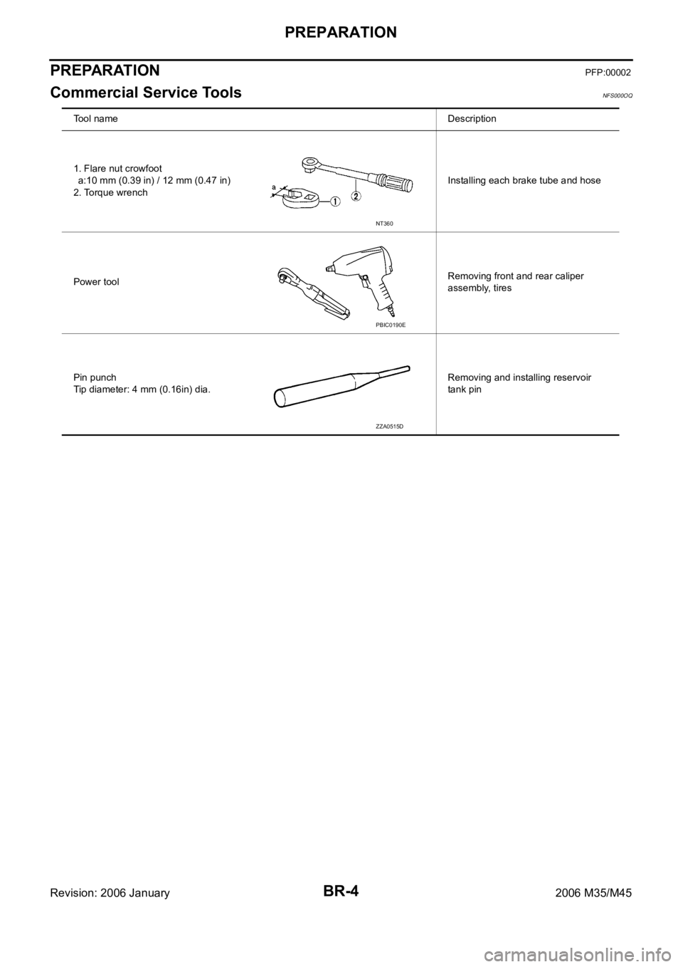
Commercial Service ToolsNFS000OQ
Tool nameDescription
1. Flare nut crowfoot
a:10 mm (0.39 in) / 12 mm (0.47 in)
2. Torque wrenchInstalling each brake tube and hose
Power toolRemoving front and rear caliper
assembly, tires
Pin punch
Tip diameter: 4 mm (0.16in) dia.Removing and installing reservoir
tank pin
NT360
PBIC0190E
ZZA0515D
Page 1280 of 5621

NOISE, VIBRATION AND HARSHNESS (NVH) TROUBLESHOOTING
BR-5
C
D
E
G
H
I
J
K
L
MA
B
BR
Revision: 2006 January2006 M35/M45
NOISE, VIBRATION AND HARSHNESS (NVH) TROUBLESHOOTINGPFP:00003
NVH Troubleshooting ChartNFS000OR
Use the chart below to help you find the cause of the symptom. If necessary, repair or replace these parts.
: Applicable Reference page
BR-23
, BR-29
BR-23
, BR-29
BR-23
, BR-29
—
—
BR-28
, BR-34
—
—
—
BR-28
, BR-34
—
NVH in PR section
NHV in RFD section
NVH in FAX, RAX and FSU, RSU section
NVH in WT section
NVH in WT section
NVH in RAX section
NVH in PS section
Possible cause and
SUSPECTED PARTS
Pads - damaged
Pads - uneven wear
Shims damaged
Rotor imbalance
Rotor damage
Rotor runout
Rotor deformation
Rotor deflection
Rotor rust
Rotor thickness variation
Drum out of round
PROPELLER SHAFT
DIFFERENTIAL
AXLE AND SUSPENSION
TIRES
ROAD WHEEL
DRIVE SHAFT
STEERING
Symptom BRAKENoiseShake
Shimmy, Judder
Page 1299 of 5621

BR-24
FRONT DISC BRAKE
Revision: 2006 January2006 M35/M45
It is not necessary to remove bolts on torque member and brake hose except for disassembly or
replacement of caliper assembly. In this case, hang cylinder body with a wire so as not to stretch
brake hose.
Do not damage piston boot.
If any shim is subject to serious corrosion, replace it with a new one.
Always replace shim and shim cover as a set when replacing brake pads.
Keep rotor free from brake fluid.
Burnish the brake pads and disc rotor mutually contacting surfaces, after refinishing or replacing
rotors, after replacing pads, or if a soft pedal occurs at very low mileage. Refer to BR-28, "
BRAKE
BURNISHING PROCEDURE" .
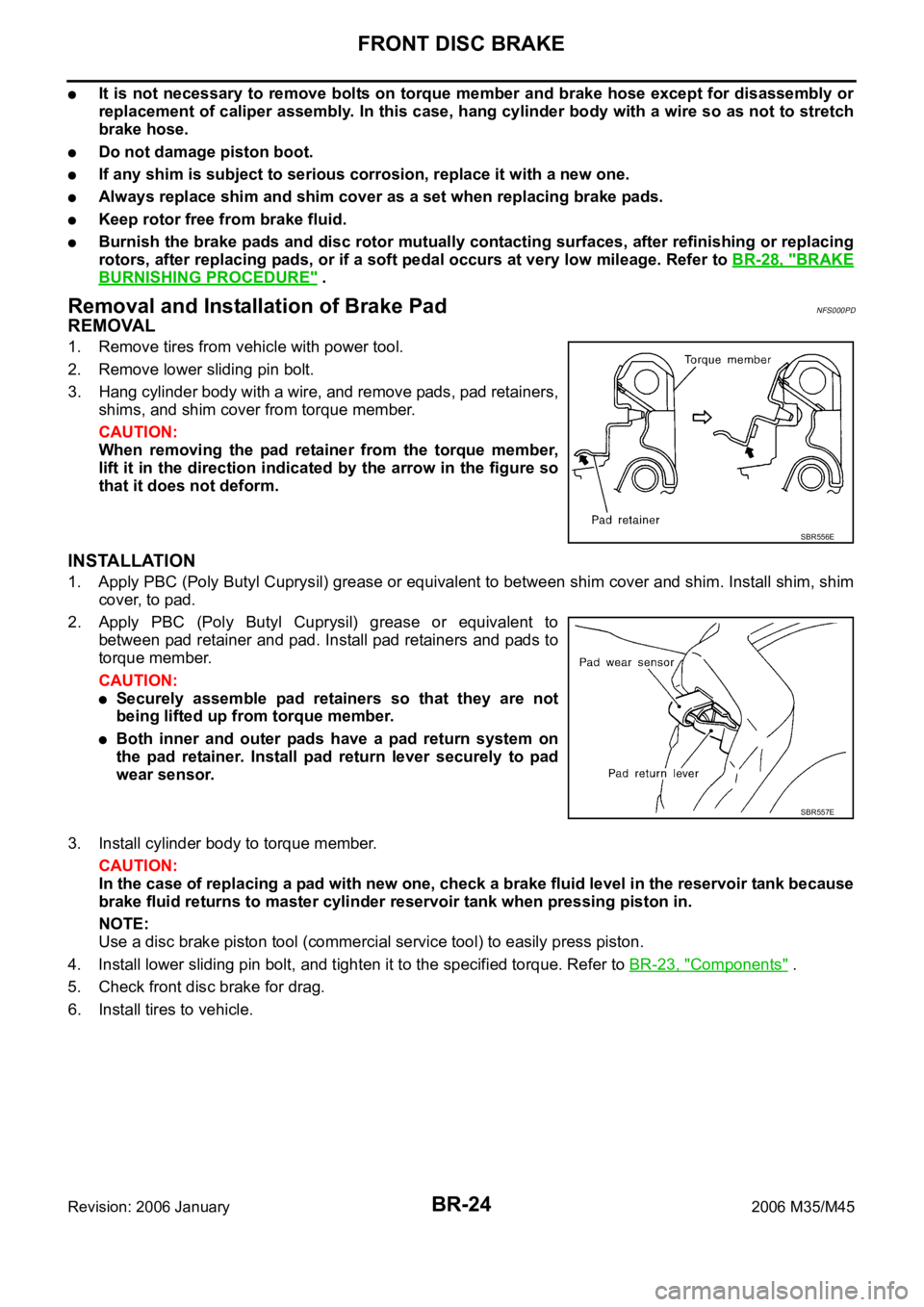
Removal and Installation of Brake PadNFS000PD
REMOVAL
1. Remove tires from vehicle with power tool.
2. Remove lower sliding pin bolt.
3. Hang cylinder body with a wire, and remove pads, pad retainers,
shims, and shim cover from torque member.
CAUTION:
When removing the pad retainer from the torque member,
lift it in the direction indicated by the arrow in the figure so
that it does not deform.
INSTALLATION
1. Apply PBC (Poly Butyl Cuprysil) grease or equivalent to between shim cover and shim. Install shim, shim
cover, to pad.
2. Apply PBC (Poly Butyl Cuprysil) grease or equivalent to
between pad retainer and pad. Install pad retainers and pads to
torque member.
CAUTION:
Securely assemble pad retainers so that they are not
being lifted up from torque member.
Both inner and outer pads have a pad return system on
the pad retainer. Install pad return lever securely to pad
wear sensor.
3. Install cylinder body to torque member.
CAUTION:
In the case of replacing a pad with new one, check a brake fluid level in the reservoir tank because
brake fluid returns to master cylinder reservoir tank when pressing piston in.
NOTE:
Use a disc brake piston tool (commercial service tool) to easily press piston.
4. Install lower sliding pin bolt, and tighten it to the specified torque. Refer to BR-23, "
Components" .
5. Check front disc brake for drag.
6. Install tires to vehicle.
SBR556E
SBR557E
Page 1300 of 5621

FRONT DISC BRAKE
BR-25
C
D
E
G
H
I
J
K
L
MA
B
BR
Revision: 2006 January2006 M35/M45
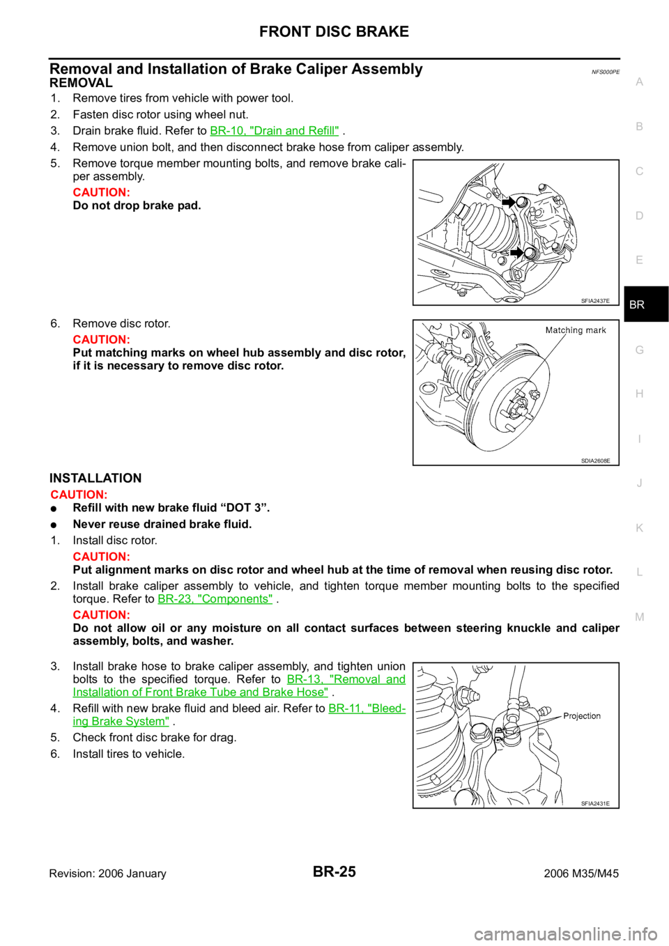
Removal and Installation of Brake Caliper AssemblyNFS000PE
REMOVAL
1. Remove tires from vehicle with power tool.
2. Fasten disc rotor using wheel nut.
3. Drain brake fluid. Refer to BR-10, "
Drain and Refill" .
4. Remove union bolt, and then disconnect brake hose from caliper assembly.
5. Remove torque member mounting bolts, and remove brake cali-
per assembly.
CAUTION:
Do not drop brake pad.
6. Remove disc rotor.
CAUTION:
Put matching marks on wheel hub assembly and disc rotor,
if it is necessary to remove disc rotor.
INSTALLATION
CAUTION:
Refill with new brake fluid “DOT 3”.
Never reuse drained brake fluid.
1. Install disc rotor.
CAUTION:
Put alignment marks on disc rotor and wheel hub at the time of removal when reusing disc rotor.
2. Install brake caliper assembly to vehicle, and tighten torque member mounting bolts to the specified
torque. Refer to BR-23, "
Components" .
CAUTION:
Do not allow oil or any moisture on all contact surfaces between steering knuckle and caliper
assembly, bolts, and washer.
3. Install brake hose to brake caliper assembly, and tighten union
bolts to the specified torque. Refer to BR-13, "
Removal and
Installation of Front Brake Tube and Brake Hose" .
4. Refill with new brake fluid and bleed air. Refer to BR-11, "
Bleed-
ing Brake System" .
5. Check front disc brake for drag.
6. Install tires to vehicle.
SFIA2437E
SDIA2608E
SFIA2431E
Page 1305 of 5621

BR-30
REAR DISC BRAKE
Revision: 2006 January2006 M35/M45
WAR NING :
Clean dust on caliper and brake pad with a vacuum dust collector to minimize the hazard of air borne
particles or other materials.
CAUTION:
While removing cylinder body, do not depress brake pedal because piston will pop out.
It is not necessary to remove bolts on torque member and brake hose except for disassembly or
replacement of caliper assembly. In this case, hang cylinder body with a wire so as not to stretch
brake hose.
Do not damage piston boot.
If any shim is subject to serious corrosion, replace it with a new one.
Always replace shim and shim covers as a set when replacing brake pads.
Keep rotor free from brake fluid.
Burnish the brake pads and disc rotor mutually contacting surfaces after refinishing or replacing
rotors, after replacing pads, or if a soft pedal occurs at very low mileage. Refer to BR-34, "
BRAKE
BURNISHING PROCEDURE" .
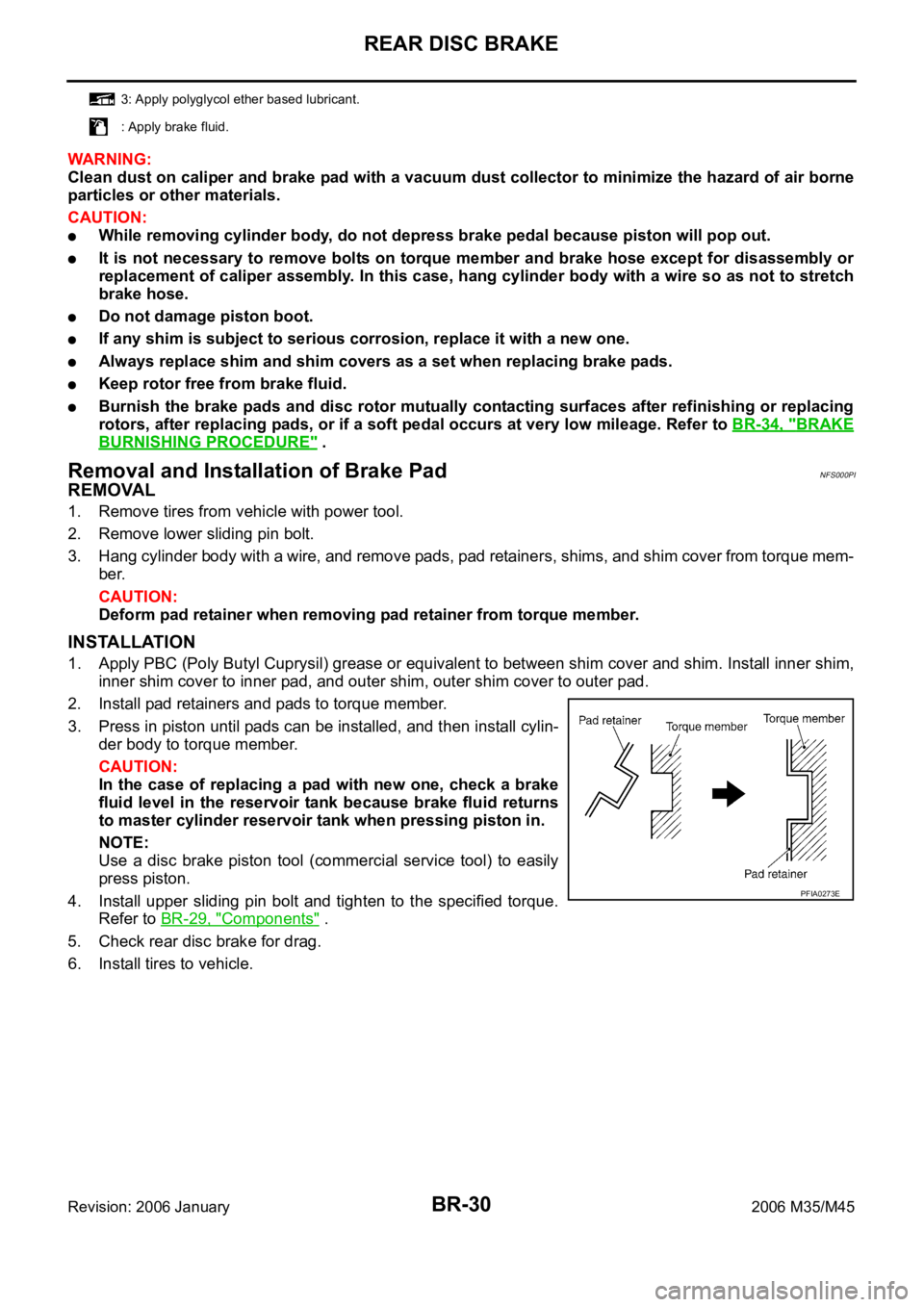
Removal and Installation of Brake PadNFS000PI
REMOVAL
1. Remove tires from vehicle with power tool.
2. Remove lower sliding pin bolt.
3. Hang cylinder body with a wire, and remove pads, pad retainers, shims, and shim cover from torque mem-
ber.
CAUTION:
Deform pad retainer when removing pad retainer from torque member.
INSTALLATION
1. Apply PBC (Poly Butyl Cuprysil) grease or equivalent to between shim cover and shim. Install inner shim,
inner shim cover to inner pad, and outer shim, outer shim cover to outer pad.
2. Install pad retainers and pads to torque member.
3. Press in piston until pads can be installed, and then install cylin-
der body to torque member.
CAUTION:
In the case of replacing a pad with new one, check a brake
fluid level in the reservoir tank because brake fluid returns
to master cylinder reservoir tank when pressing piston in.
NOTE:
Use a disc brake piston tool (commercial service tool) to easily
press piston.
4. Install upper sliding pin bolt and tighten to the specified torque.
Refer to BR-29, "
Components" .
5. Check rear disc brake for drag.
6. Install tires to vehicle.
3: Apply polyglycol ether based lubricant.
: Apply brake fluid.
PFIA0273E