2006 INFINITI M35 set clock
[x] Cancel search: set clockPage 2324 of 5621
![INFINITI M35 2006 Factory Service Manual ON BOARD DIAGNOSTIC (OBD) SYSTEM
EC-781
[VK45DE]
C
D
E
F
G
H
I
J
K
L
MA
EC
Revision: 2006 January2006 M35/M45
MIL Flashing Without DTC
When any SRT codes are not set, MIL may flash without DTC. For th INFINITI M35 2006 Factory Service Manual ON BOARD DIAGNOSTIC (OBD) SYSTEM
EC-781
[VK45DE]
C
D
E
F
G
H
I
J
K
L
MA
EC
Revision: 2006 January2006 M35/M45
MIL Flashing Without DTC
When any SRT codes are not set, MIL may flash without DTC. For th](/manual-img/42/57023/w960_57023-2323.png)
ON BOARD DIAGNOSTIC (OBD) SYSTEM
EC-781
[VK45DE]
C
D
E
F
G
H
I
J
K
L
MA
EC
Revision: 2006 January2006 M35/M45
MIL Flashing Without DTC
When any SRT codes are not set, MIL may flash without DTC. For the details, refer to EC-773, "How to Dis-
play SRT Status" .
HOW TO SWITCH DIAGNOSTIC TEST MODE
NOTE:
It is better to count the time accurately with a clock.
It is impossible to switch the diagnostic mode when an accelerator pedal position sensor circuit
has a malfunction.
Always ECM returns to Diagnostic Test Mode I after ignition switch is turned OFF.
How to Set Diagnostic Test Mode II (Self-diagnostic Results)
1. Confirm that accelerator pedal is fully released, turn ignition switch ON and wait 3 seconds.
2. Repeat the following procedure quickly five times within 5 seconds.
a. Fully depress the accelerator pedal.
b. Fully release the accelerator pedal.
3. Wait 7 seconds, fully depress the accelerator pedal and keep it for approx. 10 seconds until the MIL starts
blinking.
NOTE:
Do not release the accelerator pedal for 10 seconds if MIL may start blinking on the halfway of this
10 seconds. This blinking is displaying SRT status and is continued for another 10 seconds. For
the details, refer to EC-773, "
How to Display SRT Status" .
4. Fully release the accelerator pedal.
ECM has entered to Diagnostic Test Mode II (Self-diagnostic results).
NOTE:
Wait until the same DTC (or 1st trip DTC) appears to confirm all DTCs certainly.
How to Erase Diagnostic Test Mode II (Self-diagnostic Results)
1. Set ECM in Diagnostic Test Mode II (Self-diagnostic results). Refer to EC-781, "How to Set Diagnostic
Test Mode II (Self-diagnostic Results)" .
2. Fully depress the accelerator pedal and keep it for more than 10 seconds.
The emission-related diagnostic information has been erased from the backup memory in the ECM.
3. Fully release the accelerator pedal, and confirm the DTC 0000 is displayed.
DIAGNOSTIC TEST MODE I — BULB CHECK
In this mode, the MIL on the instrument panel should stay ON. If it remains OFF, check the bulb. Refer to DI-
40, "WARNING LAMPS" or see EC-1459, "MIL AND DATA LINK CONNECTOR" .
DIAGNOSTIC TEST MODE I — MALFUNCTION WARNING
This DTC number is clarified in Diagnostic Test Mode II (SELF-DIAGNOSTIC RESULTS)
DIAGNOSTIC TEST MODE II — SELF-DIAGNOSTIC RESULTS
In this mode, the DTC and 1st trip DTC are indicated by the number of blinks of the MIL as shown below.
PBIB0092E
MIL Condition
ON When the malfunction is detected.
OFF No malfunction.
Page 3118 of 5621
![INFINITI M35 2006 Factory Service Manual FRONT TIMING CHAIN CASE
EM-55
[VQ35DE]
C
D
E
F
G
H
I
J
K
L
MA
EM
Revision: 2006 January2006 M35/M45
18. Remove collared O-ring from front timing chain case (left and
right side).
19. Remove r INFINITI M35 2006 Factory Service Manual FRONT TIMING CHAIN CASE
EM-55
[VQ35DE]
C
D
E
F
G
H
I
J
K
L
MA
EM
Revision: 2006 January2006 M35/M45
18. Remove collared O-ring from front timing chain case (left and
right side).
19. Remove r](/manual-img/42/57023/w960_57023-3117.png)
FRONT TIMING CHAIN CASE
EM-55
[VQ35DE]
C
D
E
F
G
H
I
J
K
L
MA
EM
Revision: 2006 January2006 M35/M45
18. Remove collared O-ring from front timing chain case (left and
right side).
19. Remove rocker covers (right and left banks). Refer toEM-51, "
ROCKER COVER" .
NOTE:
When only timing chain (primary) is removed, rocker cover does not need to be removed.
20. Obtain No. 1 cylinder at TDC of its compression stroke as follows:
NOTE:
When timing chain is not removed/installed, this step is not required.
a. Rotate crankshaft pulley clockwise to align timing mark (grooved
line without color) with timing indicator.
b. Make sure that intake and exhaust cam noses on No. 1 cylinder
(engine front side of right bank) are located as shown in the fig-
ure.
If not, turn crankshaft one revolution (360 degrees) and align
as shown in the figure.
NOTE:
When only timing chain (primary) is removed, rocker cover does
not need to be removed. To make sure that No. 1 cylinder is at
its compression TDC, remove front timing chain case first. Then
check mating marks on camshaft sprockets. Refer to EM-72,
"INSTALLATION" .
21. Remove crankshaft pulley as follows:
a. Remove rear cover plate (2WD models) or starter motor (AWD
models) and set ring gear stopper (SST) as shown in the figure.
Refer to SC-10, "
STARTING SYSTEM" .
PBIC2631E
KBIA1717J
SEM418G
PBIC1098E
Page 3156 of 5621
![INFINITI M35 2006 Factory Service Manual CAMSHAFT
EM-93
[VQ35DE]
C
D
E
F
G
H
I
J
K
L
MA
EM
Revision: 2006 January2006 M35/M45
Summary of the inspection items:
* Transmission/transaxle/CVT fluid, power steering fluid, brake fluid, etc.
Va l v INFINITI M35 2006 Factory Service Manual CAMSHAFT
EM-93
[VQ35DE]
C
D
E
F
G
H
I
J
K
L
MA
EM
Revision: 2006 January2006 M35/M45
Summary of the inspection items:
* Transmission/transaxle/CVT fluid, power steering fluid, brake fluid, etc.
Va l v](/manual-img/42/57023/w960_57023-3155.png)
CAMSHAFT
EM-93
[VQ35DE]
C
D
E
F
G
H
I
J
K
L
MA
EM
Revision: 2006 January2006 M35/M45
Summary of the inspection items:
* Transmission/transaxle/CVT fluid, power steering fluid, brake fluid, etc.
Va l v e C l e a r a n c eNBS004NN
INSPECTION
Perform inspection as follows after removal, installation or replacement of camshaft or valve-related parts, or if
there is unusual engine conditions regarding valve clearance.
In cases of removing/installing or replacing camshaft and valve-
related parts, or of unusual engine conditions due to changes in
valve clearance (found malfunctions during stating, idling or causing
noise), perform inspection as follows:
1. Remove rocker covers (right and left bank). Refer to EM-51, "
ROCKER COVER" .
2. Measure the valve clearance as follows:
a. Set No. 1 cylinder at TDC of its compression stroke.
Rotate crankshaft pulley clockwise to align timing mark
(grooved line without color) with timing indicator.
Make sure that intake and exhaust cam nose on No. 1 cylin-
der (engine front side of right bank) are located as shown in
the figure.
If not, turn crankshaft one revolution (360 degrees) and align
as shown in the figure.
Item Before starting engine Engine running After engine stopped
Engine coolant Level Leakage Level
Engine oil Level Leakage Level
Other oils and fluid* Level Leakage Level
Fuel Leakage Leakage Leakage
SEM713A
KBIA1717J
SEM418G
Page 3286 of 5621
![INFINITI M35 2006 Factory Service Manual CAMSHAFT
EM-223
[VK45DE]
C
D
E
F
G
H
I
J
K
L
MA
EM
Revision: 2006 January2006 M35/M45
2. Measure the valve clearance as follows:
a. Set No. 1 cylinder at TDC of its compression stroke.
Rotate cranksh INFINITI M35 2006 Factory Service Manual CAMSHAFT
EM-223
[VK45DE]
C
D
E
F
G
H
I
J
K
L
MA
EM
Revision: 2006 January2006 M35/M45
2. Measure the valve clearance as follows:
a. Set No. 1 cylinder at TDC of its compression stroke.
Rotate cranksh](/manual-img/42/57023/w960_57023-3285.png)
CAMSHAFT
EM-223
[VK45DE]
C
D
E
F
G
H
I
J
K
L
MA
EM
Revision: 2006 January2006 M35/M45
2. Measure the valve clearance as follows:
a. Set No. 1 cylinder at TDC of its compression stroke.
Rotate crankshaft pulley in clockwise to align TDC identifica-
tion notch (without paint mark) with timing indicator on front
cover.
Make sure that both intake and exhaust cam noses of No. 1
cylinder (engine front side of left bank) are located as shown
in the figure.
If not, turn crankshaft one revolution (360 degrees) and align
as shown in the figure.
b. Use feeler gauge, measure the clearance between valve lifter
and camshaft.
Valve clearance:
Unit: mm (in)
*:Approximately 80
C (176F)
PBIC2341E
KBIA0400J
SEM139D
Cold Hot * (reference data)
Intake 0.26 - 0.34 (0.010 - 0.013) 0.304 - 0.416 (0.012 - 0.016)
Exhaust 0.29 - 0.37 (0.011 - 0.015) 0.308 - 0.432 (0.012 - 0.017)
Page 4965 of 5621

PS-12
STEERING WHEEL
Revision: 2006 January2006 M35/M45
Removal and InstallationNGS000D9
REMOVAL
NOTE:
When reconnecting spiral cable, fix cable with a tape so that fixing case and rotating part keep aligned. This
will omit neutral position alignment procedure during spiral cable installation.
1. Set vehicle to the straight-ahead position.
2. Remove driver air bag module. Refer to SRS-38, "
DRIVER AIR BAG MODULE" .
3. Remove steering wheel lock nut after steering is locked.
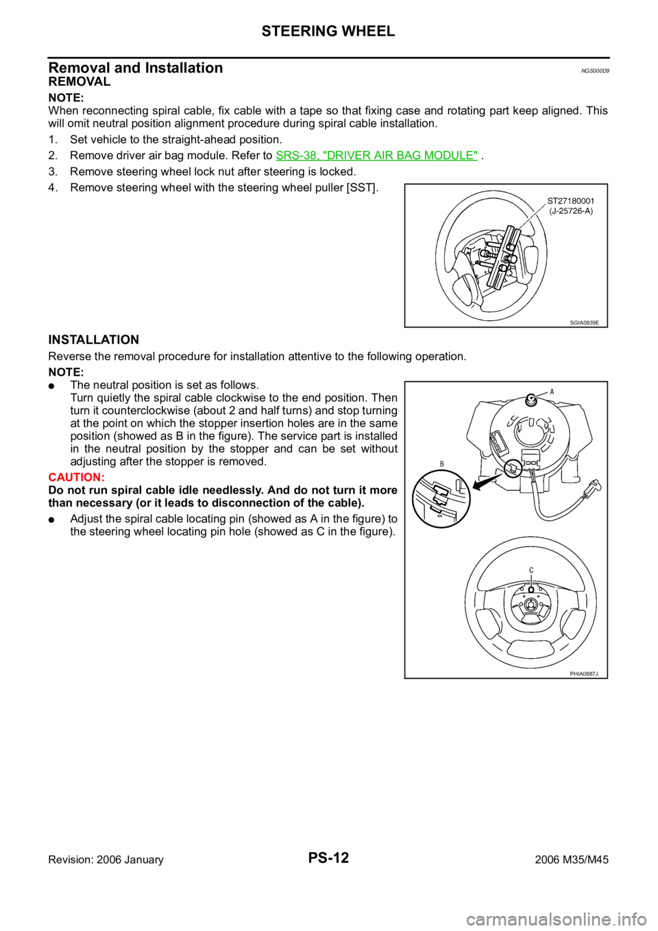
4. Remove steering wheel with the steering wheel puller [SST].
INSTALLATION
Reverse the removal procedure for installation attentive to the following operation.
NOTE:
The neutral position is set as follows.
Turn quietly the spiral cable clockwise to the end position. Then
turn it counterclockwise (about 2 and half turns) and stop turning
at the point on which the stopper insertion holes are in the same
position (showed as B in the figure). The service part is installed
in the neutral position by the stopper and can be set without
adjusting after the stopper is removed.
CAUTION:
Do not run spiral cable idle needlessly. And do not turn it more
than necessary (or it leads to disconnection of the cable).
Adjust the spiral cable locating pin (showed as A in the figure) to
the steering wheel locating pin hole (showed as C in the figure).
SGIA0939E
PHIA0887J
Page 4979 of 5621

PS-26
POWER STEERING GEAR
Revision: 2006 January2006 M35/M45
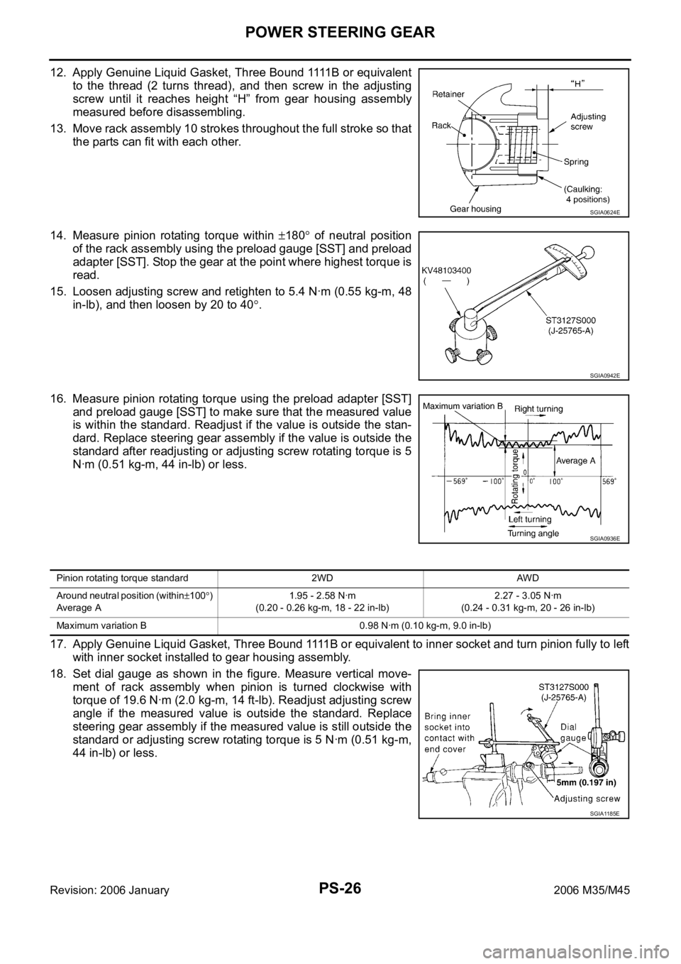
1 2 . A p p l y G e n u i n e L i q u i d G a s k e t , T h r e e B o u n d 1111 B o r e q u i v a l e n t
to the thread (2 turns thread), and then screw in the adjusting
screw until it reaches height “H” from gear housing assembly
measured before disassembling.
13. Move rack assembly 10 strokes throughout the full stroke so that
the parts can fit with each other.
14. Measure pinion rotating torque within
180 of neutral position
of the rack assembly using the preload gauge [SST] and preload
adapter [SST]. Stop the gear at the point where highest torque is
read.
15. Loosen adjusting screw and retighten to 5.4 Nꞏm (0.55 kg-m, 48
in-lb), and then loosen by 20 to 40
.
16. Measure pinion rotating torque using the preload adapter [SST]
and preload gauge [SST] to make sure that the measured value
is within the standard. Readjust if the value is outside the stan-
dard. Replace steering gear assembly if the value is outside the
standard after readjusting or adjusting screw rotating torque is 5
Nꞏm (0.51 kg-m, 44 in-lb) or less.
17. Apply Genuine Liquid Gasket, Three Bound 1111B or equivalent to inner socket and turn pinion fully to left
with inner socket installed to gear housing assembly.
18. Set dial gauge as shown in the figure. Measure vertical move-
ment of rack assembly when pinion is turned clockwise with
torque of 19.6 Nꞏm (2.0 kg-m, 14 ft-lb). Readjust adjusting screw
angle if the measured value is outside the standard. Replace
steering gear assembly if the measured value is still outside the
standard or adjusting screw rotating torque is 5 Nꞏm (0.51 kg-m,
44 in-lb) or less.
SGIA0624E
SGIA0942E
SGIA0936E
Pinion rotating torque standard 2WD AWD
Around neutral position (within
100)
Average A1.95 - 2.58 Nꞏm
(0.20 - 0.26 kg-m, 18 - 22 in-lb)2.27 - 3.05 Nꞏm
(0.24 - 0.31 kg-m, 20 - 26 in-lb)
Maximum variation B 0.98 Nꞏm (0.10 kg-m, 9.0 in-lb)
SGIA1185E
Page 5402 of 5621

SPIRAL CABLE
SRS-41
C
D
E
F
G
I
J
K
L
MA
B
SRS
Revision: 2006 January2006 M35/M45
CAUTION:
The spiral cable may snap by steering operation if the cable
is installed in an improper position.
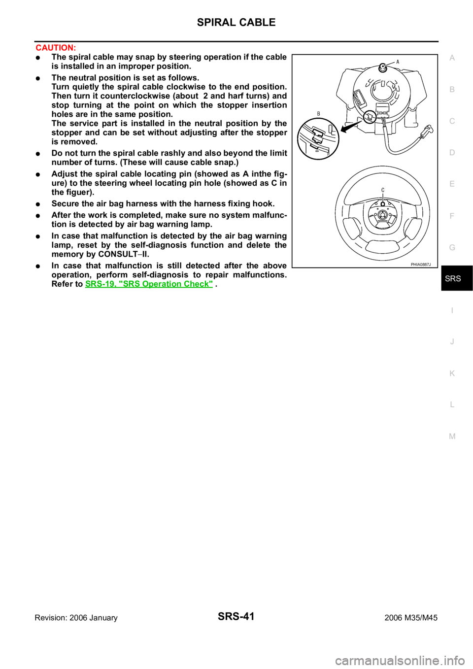
The neutral position is set as follows.
Turn quietly the spiral cable clockwise to the end position.
Then turn it counterclockwise (about 2 and harf turns) and
stop turning at the point on which the stopper insertion
holes are in the same position.
The service part is installed in the neutral position by the
stopper and can be set without adjusting after the stopper
is removed.
Do not turn the spiral cable rashly and also beyond the limit
number of turns. (These will cause cable snap.)
Adjust the spiral cable locating pin (showed as A inthe fig-
ure) to the steering wheel locating pin hole (showed as C in
the figuer).
Secure the air bag harness with the harness fixing hook.
After the work is completed, make sure no system malfunc-
tion is detected by air bag warning lamp.
In case that malfunction is detected by the air bag warning
lamp, reset by the self-diagnosis function and delete the
memory by CONSULT
II.
In case that malfunction is still detected after the above
operation, perform self-diagnosis to repair malfunctions.
Refer to SRS-19, "
SRS Operation Check" .
PHIA0887J