2006 INFINITI M35 seat adjustment
[x] Cancel search: seat adjustmentPage 1276 of 5621
BR-1
BRAKE SYSTEM
F BRAKES
CONTENTS
C
D
E
G
H
I
J
K
L
M
SECTION BR
A
B
BR
Revision: 2006 January2006 M35/M45
BRAKE SYSTEM
PRECAUTIONS .......................................................... 3
Precautions for Supplemental Restraint System
(SRS) “AIR BAG” and “SEAT BELT PRE-TEN-
SIONER” .................................................................. 3
Precautions for Procedures without Cowl Top Cover ..... 3
Precautions for Brake System .................................. 3
PREPARATION ........................................................... 4
Commercial Service Tools ........................................ 4
NOISE, VIBRATION AND HARSHNESS (NVH)
TROUBLESHOOTING ................................................ 5
NVH Troubleshooting Chart ..................................... 5
BRAKE PEDAL .......................................................... 6
Inspection and Adjustment ....................................... 6
ADJUSTMENT ...................................................... 7
Removal and Installation .......................................... 7
COMPONENTS .................................................... 7
REMOVAL ........................................................
..... 8
INSPECTION AFTER REMOVAL ......................... 8
INSTALLATION ..................................................... 9
BRAKE FLUID .......................................................... 10
On-Board Inspection .............................................. 10
CHECKING BRAKE FLUID LEVEL .................... 10
Checking Brake Line .............................................. 10
Drain and Refill ....................................................... 10
Bleeding Brake System ........................................... 11
BRAKE TUBE AND HOSE ....................................... 12
Hydraulic Circuit ..................................................... 12
Removal and Installation of Front Brake Tube and
Brake Hose ............................................................ 13
REMOVAL ........................................................
... 13
INSTALLATION ................................................... 13
Removal and Installation of Rear Brake Tube and
Brake Hose ............................................................ 13
REMOVAL ........................................................
... 13
INSTALLATION ................................................... 14
Inspection after Installation .................................... 14
BRAKE MASTER CYLINDER .................................. 15
On-Board Inspection .............................................. 15
LEAK INSPECTION ............................................ 15
Removal and Installation ........................................ 15REMOVAL ........................................................
... 15
INSTALLATION ................................................... 15
Disassembly and Assembly .................................... 16
COMPONENTS ................................................... 16
Disassembly and Assembly .................................... 16
DISASSEMBLY ................................................... 16
ASSEMBLY ......................................................... 17
BRAKE BOOSTER ................................................... 18
On-Board Inspection and Service ........................... 18
OPERATION CHECK .......................................... 18
AIR TIGHT CHECK ............................................. 18
Removal and Installation ........................................ 19
COMPONENTS ................................................... 19
REMOVAL ........................................................
... 19
INSTALLATION ................................................... 19
VACUUM LINES ....................................................... 21
Components ........................................................... 21
Removal and Installation ........................................ 22
Inspection ............................................................... 22
VISUAL INSPECTION ......................................... 22
CHECK VALVE INSPECTION ............................. 22
FRONT DISC BRAKE ............................................... 23
On-Board Inspection ............................................
... 23
PAD WEAR INSPECTION ................................... 23
Components ........................................................... 23
Removal and Installation of Brake Pad .................. 24
REMOVAL ........................................................
... 24
INSTALLATION ................................................... 24
Removal and Installation of Brake Caliper Assembly
... 25
REMOVAL ........................................................
... 25
INSTALLATION ................................................... 25
Disassembly and Assembly of Brake Caliper
Assembly ................................................................ 26
DISASSEMBLY ................................................... 26
INSPECTION AFTER DISASSEMBLY ................ 26
ASSEMBLY ......................................................... 27
DISC ROTOR INSPECTION ............................... 28
BRAKE BURNISHING PROCEDURE ................. 28
REAR DISC BRAKE ................................................. 29
Page 1282 of 5621
BRAKE PEDAL
BR-7
C
D
E
G
H
I
J
K
L
MA
B
BR
Revision: 2006 January2006 M35/M45
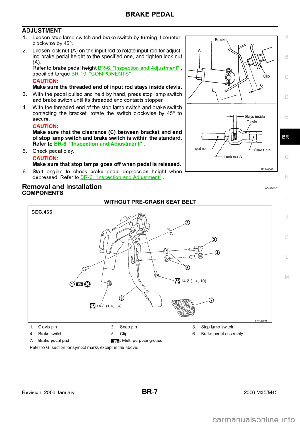
ADJUSTMENT
1. Loosen stop lamp switch and brake switch by turning it counter-
clockwise by 45
.
2. Loosen lock nut (A) on the input rod to rotate input rod for adjust-
ing brake pedal height to the specified one, and tighten lock nut
(A).
Refer to brake pedal height BR-6, "
Inspection and Adjustment" ,
specified torque BR-19, "
COMPONENTS" .
CAUTION:
Make sure the threaded end of input rod stays inside clevis.
3. With the pedal pulled and held by hand, press stop lamp switch
and brake switch until its threaded end contacts stopper.
4. With the threaded end of the stop lamp switch and brake switch
contacting the bracket, rotate the switch clockwise by 45
to
secure.
CAUTION:
Make sure that the clearance (C) between bracket and end
of stop lamp switch and brake switch is within the standard.
Refer to BR-6, "
Inspection and Adjustment" .
5. Check pedal play.
CAUTION:
Make sure that stop lamps goes off when pedal is released.
6. Start engine to check brake pedal depression height when
depressed. Refer to BR-6, "
Inspection and Adjustment" .
Removal and InstallationNFS000OT
COMPONENTS
WITHOUT PRE-CRASH SEAT BELT
PFIA0436E
SFIA2951E
1. Clevis pin 2. Snap pin 3. Stop lamp switch
4. Brake switch 5. Clip 6. Brake pedal assembly
7. Brake pedal pad : Multi-purpose grease
Refer to GI section for symbol marks except in the above.
Page 1312 of 5621
BRC-1
BRAKE CONTROL SYSTEM
F BRAKES
CONTENTS
C
D
E
G
H
I
J
K
L
M
SECTION BRC
A
B
BRC
Revision: 2006 January2006 M35/M45
BRAKE CONTROL SYSTEM
VDC/TCS/ABS
PRECAUTIONS .......................................................... 3
Precautions for Supplemental Restraint System
(SRS) “AIR BAG” and “SEAT BELT PRE-TEN-
SIONER” .................................................................. 3
Precautions for Procedures without Cowl Top Cover ..... 3
Precautions for Brake System .................................. 3
Precautions for Brake Control .................................. 4
PREPARATION ........................................................... 5
Special Service Tools ............................................... 5
Commercial Service Tools ........................................ 5
ON-VEHICLE SERVICE ............................................. 6
Adjustment of Steering Angle Sensor Neutral Posi-
tion ........................................................................... 6
SYSTEM DESCRIPTION ............................................ 7
System Diagram ....................................................... 7
Function ................................................................... 7
ABS ....................................................................... 7
EBD ....................................................................... 7
TCS ....................................................................... 7
VDC ....................................................................... 8
ECD ....................................................................... 8
Operation That Is Not "System Error" ...................... 8
ABS ....................................................................... 8
TCS ....................................................................... 8
VDC ....................................................................... 8
Fail-Safe Function .................................................... 8
ABS, EBD SYSTEM .............................................. 8
VDC / TCS ............................................................ 9
Hydraulic Circuit Diagram ........................................ 9
CAN COMMUNICATION .......................................... 10
System Description ................................................ 10
TROUBLE DIAGNOSIS .............................................11
How to Perform Trouble Diagnoses ........................ 11
BASIC CONCEPT ................................................ 11
DIAGNOSIS FLOW CHART ............................... 12
ASKING COMPLAINTS ...................................... 13
EXAMPLE OF DIAGNOSIS WORKSHEET ........ 13
Component Parts Location ..................................... 14
Schematic .............................................................. 15Wiring Diagram — VDC — ..................................... 16
CONSULT-II Functions (ABS) ................................ 22
CONSULT-II MAIN FUNCTION ........................... 22
CONSULT-II BASIC OPERATION PROCEDURE
... 22
Self-Diagnosis .....................................................
... 23
OPERATION PROCEDURE ................................ 23
ERASE MEMORY ............................................... 23
DISPLAY ITEM LIST ........................................... 24
Data Monitor ........................................................... 27
OPERATION PROCEDURE ................................ 27
DISPLAY ITEM LIST ........................................... 27
Active Test .............................................................. 30
OPERATION PROCEDURE ................................ 30
TEST ITEMS ....................................................... 31
For Fast and Accurate Diagnosis ........................... 32
PRECAUTIONS FOR DIAGNOSIS ..................... 32
Basic Inspection ..................................................... 33
BASIC INSPECTION 1: BRAKE FLUID LEVEL,
LEAK INSPECTION AND BRAKE PAD .............. 33
BASIC INSPECTION 2: LOOSENESS OF
POWER SYSTEM TERMINALS AND BATTERY ... 33
BASIC INSPECTION 3: ABS WARNING LAMP,
BRAKE WARNING LAMP, VDC OFF INDICATOR
LAMP AND SLIP INDICATOR LAMP .................. 33
Inspection 1: Wheel Sensor Circuit ........................ 34
Inspection 2: Engine System .................................. 36
Inspection 3: ABS Actuator and Electric Unit (Con-
trol Unit) .................................................................. 36
Inspection 4: ABS Actuator and Electric Unit (Con-
trol Unit) Power Supply and Ground Circuit ............ 37
Inspection 5: ABS Motor and Motor Relay Circuit ... 38
Inspection 6: Solenoid, VDC Change-Over Valve
and Actuator Relay Circuit ...................................... 40
Inspection 7: Pressure Sensor Circuit .................... 41
Inspection 8: Steering Angle Sensor Circuit ........... 41
Inspection 9: Park/Neutral Position (PNP) Switch
Circuit ..................................................................... 43
Inspection 10: Stop Lamp Switch Circuit ................ 44
Inspection 11: Yaw Rate/Side G Sensor Circuit ..... 45
Page 1435 of 5621

DI-2Revision: 2006 January2006 M35/M45 A/T INDICATOR ........................................................ 56
System Description ................................................. 56
MANUAL MODE .................................................. 56
NOT MANUAL MODE ......................................... 56
Wiring Diagram — AT/IND — ................................. 57
A/T Indicator Is Malfunction .................................... 59
WARNING CHIME .................................................. ... 60
System Description ................................................. 60
POWER SUPPLY AND GROUND CIRCUIT ....... 60
IGNITION KEY WARNING CHIME (WITH INTEL-
LIGENT KEY) ...................................................... 61
LIGHT WARNING CHIME ................................... 61
SEAT BELT WARNING CHIME ........................... 61
Component Parts and Harness Connector Location ... 62
Schematic ............................................................... 63
Wiring Diagram — CHIME — ................................. 64
Terminals and Reference Value for Combination
Meter ...................................................................... 67
Terminals and Reference Value for Unified Meter
and A/C Amp. ......................................................... 67
Terminals and Reference Value for BCM ................ 68
CONSULT-II Function (BCM) .................................. 69
CONSULT-II BASIC OPERATION ....................... 69
DATA MONITOR .................................................. 70
ACTIVE TEST ..................................................... 71
SELF-DIAG RESULTS ........................................ 71
CONSULT-II Function (METER A/C AMP) ............. 71
Trouble Diagnosis ................................................... 71
HOW TO PERFORM TROUBLE DIAGNOSIS .... 71
PRELIMINARY INSPECTION ............................. 71
SYMPTOM CHART ............................................. 72
Meter Buzzer Circuit Inspection .............................. 72
Lighting Switch Signal Inspection ........................... 73
Front Door Switch (Driver Side) Signal Inspection ... 73
Seat Belt Buckle Switch Signal Inspection ............. 74
Electrical Component Inspection ............................ 76
FRONT DOOR SWITCH (DRIVER SIDE) ........... 76
SEAT BELT BUCKLE SWITCH (DRIVER SIDE) ... 76
CAN COMMUNICATION ........................................... 77
System Description ................................................. 77
CAN Communication Unit ....................................... 77
LANE DEPARTURE WARNING SYSTEM ................ 78
Precautions for Lane Departure Warning (LDW)
system .................................................................... 78
System Description ................................................. 78
LDW SYSTEM OPERATION ............................... 78
POWER SUPPLY AND GROUND CIRCUIT ....... 80
Action Test ...........................................................
... 80
LDW SYSTEM RUNNING TEST ......................... 80
Camera Aiming Adjustment .................................... 81
OUTLINE ............................................................. 81
PREPARATION ................................................... 81TARGET SETTING .............................................. 81
VEHICLE HEIGHT CHECK ................................. 84
AIMING ADJUSTMENT ....................................... 84
Component Parts and Harness Connector Location ... 88
Wiring Diagram — LDW — ..................................... 89
Terminals and Reference Value for LDW Camera
Unit .......................................................................... 91
CONSULT-II Function (LDW) .................................. 91
DESCRIPTION .................................................... 91
CONSULT-II BASIC OPERATION ....................... 91
WORK SUPPORT ............................................... 92
SELF-DIAG RESULTS ......................................... 92
DATA MONITOR .................................................. 93
ACTIVE TEST ...................................................... 94
Trouble Diagnosis ................................................... 95
HOW TO PERFORM TROUBLE DIAGNOSIS .... 95
PRELIMINARY INSPECTION .............................. 95
SYMPTOM CHART .............................................. 96
Power Supply and Ground Circuit Inspection ......... 96
DTC [C1B00] CAMERA UNIT MALF ...................... 97
DTC [C1B01] CAM AIMING INCMP ....................... 97
DTC [C1B02] VHCL SPD DATA MALF ................... 97
DTC [C1B03] ABNRML TEMP DETECT ................ 97
DTC [U1000] CAN COMM CIRCUIT ...................... 98
DTC [U1010] CONTROL UNIT (CAN) .................... 98
LDW Chime Circuit Inspection ................................ 98
LDW Switch Circuit Inspection ................................ 99
LDW Indicator Lamp Circuit Inspection .................102
Turn Signal Input Inspection .................................103
Electrical Component Inspection ..........................103
LDW SWITCH ....................................................103
Removal and Installation for LDW Camera Unit ...103
REMOVAL ..........................................................103
INSTALLATION ..................................................103
Removal and Installation for LDW Chime .............104
REMOVAL ..........................................................104
INSTALLATION ..................................................104
Removal and Installation for LDW Switch .............104
COMPASS ...............................................................105
System Description ...............................................105
DIRECTION DISPLAY .......................................105
Zone Variation Change Procedure ........................105
Correction Functions of the Compass Display ......105
AUTOMATIC CORRECTION .............................105
MANUAL CORRECTION PROCEDURE ...........105
Wiring Diagram – COMPAS – ...............................106
Removal and Installation of Compass ...................107
CLOCK ....................................................................108
Wiring Diagram — CLOCK — ...............................108
Removal and Installation of Clock .........................109
REMOVAL ..........................................................109
INSTALLATION ..................................................109
Page 1544 of 5621
EC-1
ENGINE CONTROL SYSTEM
B ENGINE
CONTENTS
C
D
E
F
G
H
I
J
K
L
M
SECTION EC
A
EC
Revision: 2006 January2006 M35/M45
ENGINE CONTROL SYSTEM
VQ35DE
INDEX FOR DTC ...................................................... 16
DTC No. Index ....................................................... 16
Alphabetical Index .................................................. 20
PRECAUTIONS ........................................................ 24
Precautions for Supplemental Restraint System
(SRS) “AIR BAG” and “SEAT BELT PRE-TEN-
SIONER” ................................................................ 24
Precautions for Procedures without Cowl Top Cover ... 24
On Board Diagnostic (OBD) System of Engine and
A/T .......................................................................... 24
Precaution .............................................................. 25
PREPARATION ......................................................... 28
Special Service Tools ............................................. 28
Commercial Service Tools ...................................... 29
ENGINE CONTROL SYSTEM .................................. 30
System Diagram ..................................................... 30
Multiport Fuel Injection (MFI) System .................... 31
Electronic Ignition (EI) System ............................... 33
Fuel Cut Control (At No Load and High Engine
Speed) .................................................................... 34
AIR CONDITIONING CUT CONTROL ..................... 35
Input/Output Signal Chart ....................................... 35
System Description ................................................ 35
AUTOMATIC SPEED CONTROL DEVICE (ASCD) ... 36
System Description ................................................ 36
Component Description .......................................... 37
CAN COMMUNICATION .......................................... 38
System Description ................................................ 38
EVAPORATIVE EMISSION SYSTEM ....................... 39
Description ............................................................. 39
Component Inspection ........................................... 42
Removal and Installation ........................................ 43
How to Detect Fuel Vapor Leakage ....................... 43
ON BOARD REFUELING VAPOR RECOVERY
(ORVR) ...................................................................... 46
System Description ................................................ 46
Diagnostic Procedure ............................................. 47
Component Inspection ........................................... 49POSITIVE CRANKCASE VENTILATION ................. 51
Description .............................................................. 51
Component Inspection ............................................ 51
IVIS (INFINITI VEHICLE IMMOBILIZER SYSTEM-
NATS) ........................................................................ 53
Description .............................................................. 53
ON BOARD DIAGNOSTIC (OBD) SYSTEM ............ 54
Introduction ..................................................
........... 54
Two Trip Detection Logic ........................................ 54
Emission-Related Diagnostic Information ............... 55
Malfunction Indicator Lamp (MIL) ........................... 69
OBD System Operation Chart ................................ 72
BASIC SERVICE PROCEDURE ............................... 77
Basic Inspection ..................................................... 77
Idle Speed and Ignition Timing Check .................... 82
Idle Mixture Ratio Adjustment ................................. 84
VIN Registration ..................................................... 95
Accelerator Pedal Released Position Learning ...... 95
Throttle Valve Closed Position Learning ................. 95
Idle Air Volume Learning ........................................ 96
Fuel Pressure Check .............................................. 98
TROUBLE DIAGNOSIS ..........................................100
Trouble Diagnosis Introduction .............................100
DTC Inspection Priority Chart ...............................106
Fail-Safe Chart .....................................................108
Symptom Matrix Chart ..........................................109
Engine Control Component Parts Location ..........113
Vacuum Hose Drawing .........................................121
Circuit Diagram .....................................................122
ECM Harness Connector Terminal Layout ...........124
ECM Terminals and Reference Value ...................124
CONSULT-II Function (ENGINE) ..........................133
Generic Scan Tool (GST) Function .......................146
CONSULT-II Reference Value in Data Monitor .....149
Major Sensor Reference Graph in Data Monitor
Mode .....................................................................153
TROUBLE DIAGNOSIS - SPECIFICATION VALUE .155
Description ............................................................155
Testing Condition ..................................................155
Page 1551 of 5621

EC-8Revision: 2006 January2006 M35/M45 Wiring Diagram .....................................................708
Diagnostic Procedure ...........................................709
Component Inspection ..........................................713
ASCD INDICATOR .................................................
.714
Component Description ........................................714
CONSULT-II Reference Value in Data Monitor Mode
.714
Wiring Diagram .....................................................715
Diagnostic Procedure ...........................................716
SNOW MODE SWITCH ...........................................717
Description ............................................................717
CONSULT-II Reference Value in the Data Monitor
Mode .....................................................................717
Wiring Diagram .....................................................718
Diagnostic Procedure ...........................................719
Component Inspection ..........................................721
MIL AND DATA LINK CONNECTOR ......................722
Wiring Diagram .....................................................722
SERVICE DATA AND SPECIFICATIONS (SDS) ....724
Fuel Pressure .......................................................724
Idle Speed and Ignition Timing .............................724
Calculated Load Value ..........................................724
Mass Air Flow Sensor ...........................................724
Intake Air Temperature Sensor .............................724
Engine Coolant Temperature Sensor ...................724
Fuel Tank Temperature Sensor ............................724
Crankshaft Position Sensor (POS) .......................724
Camshaft Position Sensor (PHASE) ....................724
A/F Sensor 1 Heater ............................................ .724
Heated Oxygen Sensor 2 Heater .........................725
Throttle Control Motor ...........................................725
Fuel Injector ..........................................................725
Fuel Pump ............................................................725
VK45DE
INDEX FOR DTC .....................................................726
DTC No. Index ......................................................726
Alphabetical Index ................................................730
PRECAUTIONS .......................................................734
Precautions for Supplemental Restraint System
(SRS) “AIR BAG” and “SEAT BELT PRE-TEN-
SIONER” ...............................................................734
Precautions for Procedures without Cowl Top Cover .734
On Board Diagnostic (OBD) System of Engine and
A/T ........................................................................734
Precaution ............................................................735
PREPARATION .......................................................738
Special Service Tools ...........................................738
Commercial Service Tools ....................................739
ENGINE CONTROL SYSTEM ................................740
System Diagram ...................................................740
Multiport Fuel Injection (MFI) System ...................741
Electronic Ignition (EI) System .............................743
Fuel Cut Control (At No Load and High Engine
Speed) ..................................................................744
AIR CONDITIONING CUT CONTROL ....................745
Input/Output Signal Chart .....................................745
System Description ...............................................745AUTOMATIC SPEED CONTROL DEVICE (ASCD) .746
System Description ...............................................746
Component Description ........................................747
CAN COMMUNICATION .........................................748
System Description ...............................................748
EVAPORATIVE EMISSION SYSTEM .....................749
Description ............................................................749
Component Inspection ..........................................752
Removal and Installation .......................................753
How to Detect Fuel Vapor Leakage ......................753
ON BOARD REFUELING VAPOR RECOVERY
(ORVR) ....................................................................756
System Description ...............................................756
Diagnostic Procedure ............................................757
Component Inspection ..........................................759
POSITIVE CRANKCASE VENTILATION ................761
Description ............................................................761
Component Inspection ..........................................761
IVIS (INFINITI VEHICLE IMMOBILIZER SYSTEM-
NATS) ......................................................................763
Description ............................................................763
ON BOARD DIAGNOSTIC (OBD) SYSTEM ...........764
Introduction ..........................................................
.764
Two Trip Detection Logic .......................................764
Emission-Related Diagnostic Information .............765
Malfunction Indicator Lamp (MIL) .........................780
OBD System Operation Chart ...............................782
BASIC SERVICE PROCEDURE .............................788
Basic Inspection ....................................................788
Idle Speed and Ignition Timing Check ..................793
Idle Mixture Ratio Adjustment ...............................795
VIN Registration ....................................................806
Accelerator Pedal Released Position Learning .....806
Throttle Valve Closed Position Learning ...............806
Idle Air Volume Learning .......................................807
Fuel Pressure Check ............................................809
TROUBLE DIAGNOSIS ..........................................811
Trouble Diagnosis Introduction .............................811
DTC Inspection Priority Chart ...............................817
Fail-Safe Chart ......................................................819
Symptom Matrix Chart ..........................................820
Engine Control Component Parts Location ...........824
Vacuum Hose Drawing .........................................833
Circuit Diagram .....................................................834
ECM Harness Connector Terminal Layout ............836
ECM Terminals and Reference Value ...................836
CONSULT-II Function (ENGINE) ..........................846
Generic Scan Tool (GST) Function .......................859
CONSULT-II Reference Value in Data Monitor .....862
Major Sensor Reference Graph in Data Monitor
Mode .....................................................................866
TROUBLE DIAGNOSIS - SPECIFICATION VALUE .868
Description ............................................................868
Testing Condition ..................................................868
Inspection Procedure ...........................................
.868
Diagnostic Procedure ............................................869
TROUBLE DIAGNOSIS FOR INTERMITTENT INCI-
Page 3008 of 5621
PRECAUTIONS
EI-3
C
D
E
F
G
H
J
K
L
MA
B
EI
Revision: 2006 January2006 M35/M45
PRECAUTIONSPFP:00001
Precautions for Supplemental Restraint System (SRS) “AIR BAG” and “SEAT
BELT PRE-TENSIONER”
NIS00245
The Supplemental Restraint System such as “AIR BAG” and “SEAT BELT PRE-TENSIONER”, used along
with a front seat belt, helps to reduce the risk or severity of injury to the driver and front passenger for certain
types of collision. This system includes seat belt switch inputs and dual stage front air bag modules. The SRS
system uses the seat belt switches to determine the front air bag deployment, and may only deploy one front
air bag, depending on the severity of a collision and whether the front occupants are belted or unbelted.
Information necessary to service the system safely is included in the SRS and SB section of this Service Man-
ual.
WAR NING :
To avoid rendering the SRS inoperative, which could increase the risk of personal injury or death
in the event of a collision which would result in air bag inflation, all maintenance must be per-
formed by an authorized NISSAN/INFINITI dealer.
Improper maintenance, including incorrect removal and installation of the SRS, can lead to per-
sonal injury caused by unintentional activation of the system. For removal of Spiral Cable and Air
Bag Module, see the SRS section.
Do not use electrical test equipment on any circuit related to the SRS unless instructed to in this
Service Manual. SRS wiring harnesses can be identified by yellow and/or orange harnesses or
harness connectors.
Precautions for Procedures without Cowl Top CoverNIS00246
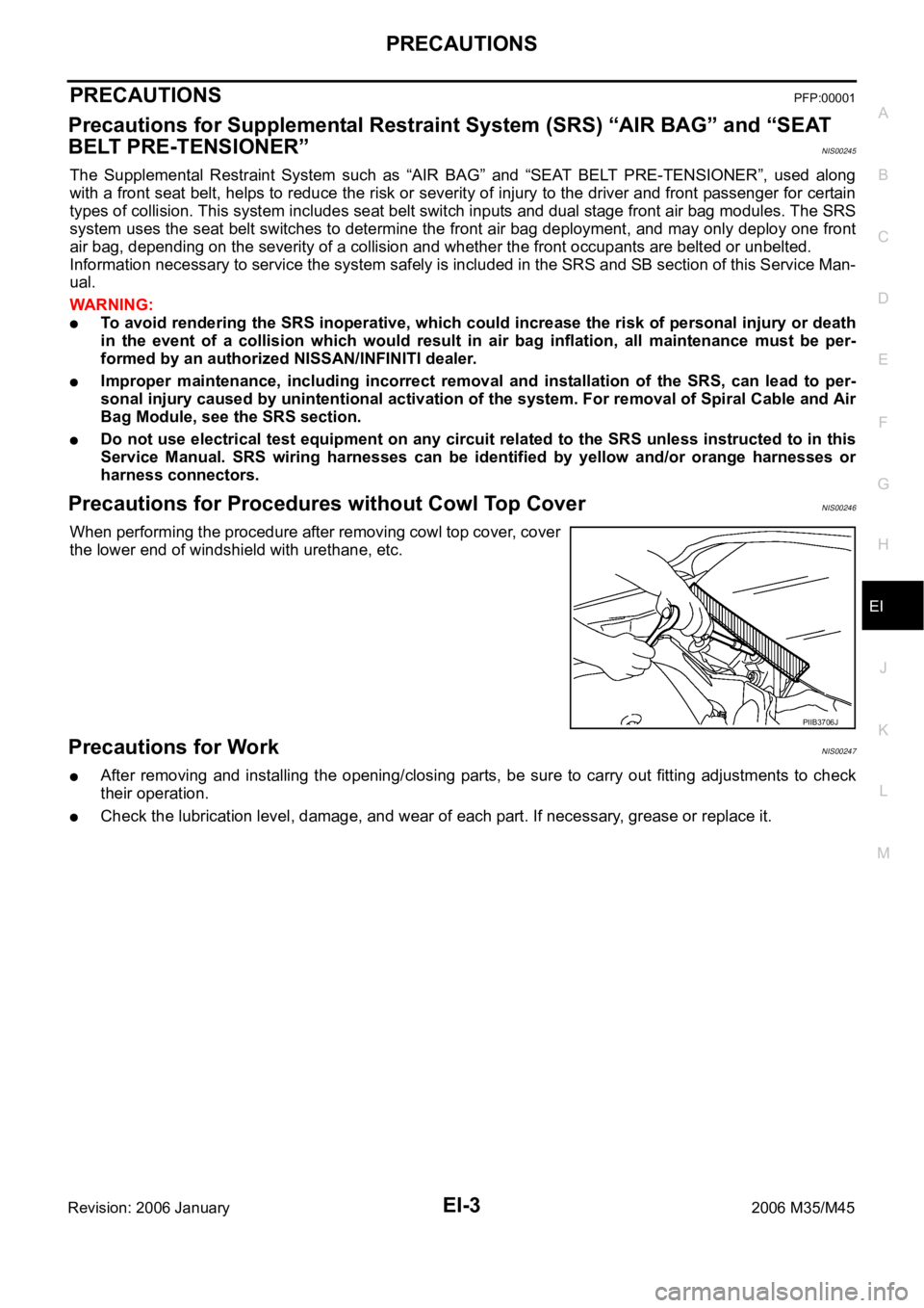
When performing the procedure after removing cowl top cover, cover
the lower end of windshield with urethane, etc.
Precautions for WorkNIS00247
After removing and installing the opening/closing parts, be sure to carry out fitting adjustments to check
their operation.
Check the lubrication level, damage, and wear of each part. If necessary, grease or replace it.
PIIB3706J
Page 3013 of 5621

EI-8
SQUEAK AND RATTLE TROUBLE DIAGNOSES
Revision: 2006 January2006 M35/M45
TRUNK
Trunk noises are often caused by a loose jack or loose items put into the trunk by the owner.
In addition look for:
1. Trunk lid dumpers out of adjustment
2. Trunk lid striker out of adjustment
3. The trunk lid torsion bars knocking together
4. A loose license plate or bracket
Most of these incidents can be repaired by adjusting, securing or insulating the item(s) or component(s) caus-
ing the noise.
SUNROOF/HEADLINING
Noises in the sunroof/headlining area can often be traced to one of the following:
1. Sunroof lid, rail, linkage or seals making a rattle or light knocking noise
2. Sunvisor shaft shaking in the holder
3. Front or rear windshield touching headlining and squeaking
Again, pressing on the components to stop the noise while duplicating the conditions can isolate most of these
incidents. Repairs usually consist of insulating with felt cloth tape.
SEATS
When isolating seat noise it's important to note the position the seat is in and the load placed on the seat when
the noise is present. These conditions should be duplicated when verifying and isolating the cause of the
noise.
Cause of seat noise include:
1. Headrest rods and holder
2. A squeak between the seat pad cushion and frame
3. The rear seatback lock and bracket
These noises can be isolated by moving or pressing on the suspected components while duplicating the con-
ditions under which the noise occurs. Most of these incidents can be repaired by repositioning the component
or applying urethane tape to the contact area.
UNDERHOOD
Some interior noise may be caused by components under the hood or on the engine wall. The noise is then
transmitted into the passenger compartment.
Causes of transmitted underhood noise include:
1. Any component mounted to the engine wall
2. Components that pass through the engine wall
3. Engine wall mounts and connectors
4. Loose radiator mounting pins
5. Hood bumpers out of adjustment
6. Hood striker out of adjustment
These noises can be difficult to isolate since they cannot be reached from the interior of the vehicle. The best
method is to secure, move or insulate one component at a time and test drive the vehicle. Also, engine RPM
or load can be changed to isolate the noise. Repairs can usually be made by moving, adjusting, securing, or
insulating the component causing the noise.