2006 INFINITI M35 fuse
[x] Cancel search: fusePage 2990 of 5621
![INFINITI M35 2006 Factory Service Manual ICC BRAKE SWITCH
EC-1447
[VK45DE]
C
D
E
F
G
H
I
J
K
L
MA
EC
Revision: 2006 January2006 M35/M45
10. DETECT MALFUNCTIONING PART
Check the following.
Fuse block (J/B) connector E101
10A fuse
Harness for INFINITI M35 2006 Factory Service Manual ICC BRAKE SWITCH
EC-1447
[VK45DE]
C
D
E
F
G
H
I
J
K
L
MA
EC
Revision: 2006 January2006 M35/M45
10. DETECT MALFUNCTIONING PART
Check the following.
Fuse block (J/B) connector E101
10A fuse
Harness for](/manual-img/42/57023/w960_57023-2989.png)
ICC BRAKE SWITCH
EC-1447
[VK45DE]
C
D
E
F
G
H
I
J
K
L
MA
EC
Revision: 2006 January2006 M35/M45
10. DETECT MALFUNCTIONING PART
Check the following.
Fuse block (J/B) connector E101
10A fuse
Harness for open or short between battery and stop lamp switch
Harness for open or short between battery and ICC brake hold relay
>> Repair open circuit or short to ground or short to power in harness or connectors.
11 . CHECK STOP LAMP SWITCH INPUT SIGNAL CIRCUIT FOR OPEN AND SHORT
1. Disconnect ECM harness connector.
2. Check harness continuity between the following;
ECM terminal 101 and stop lamp switch terminal 2,
ECM terminal 101 and ICC brake hold relay terminal 5.
Refer to Wiring Diagram.
3. Also check harness for short to ground and short to power.
OK or NG
OK >> GO TO 13.
NG >> GO TO 12.
12. DETECT MALFUNCTIONING PART
Check the following.
Harness connectors E108, M15
Harness for open or short between ECM and stop lamp switch
Harness for open or short between ECM and ICC brake hold relay
>> Repair open circuit or short to ground or short to power in harness or connectors.
13. CHECK STOP LAMP SWITCH
Refer to EC-1447, "
Component Inspection" .
OK or NG
OK >> GO TO 14.
NG >> Replace stop lamp switch.
14. CHECK ICC BRAKE HOLD RELAY
Refer to EC-1447, "
Component Inspection" .
OK >> GO TO 15.
NG >> Replace ICC brake hold relay.
15. CHECK INTERMITTENT INCIDENT
Refer to EC-878, "
TROUBLE DIAGNOSIS FOR INTERMITTENT INCIDENT" .
>>INSPECTION END
Component InspectionNBS005QI
ICC BRAKE SWITCH
1. Turn ignition switch OFF.Continuity should exist.
Page 2996 of 5621
![INFINITI M35 2006 Factory Service Manual ASCD BRAKE SWITCH
EC-1453
[VK45DE]
C
D
E
F
G
H
I
J
K
L
MA
EC
Revision: 2006 January2006 M35/M45
3. CHECK ASCD BRAKE SWITCH POWER SUPPLY CIRCUIT
1. Turn ignition switch OFF.
2. Disconnect ASCD brake sw INFINITI M35 2006 Factory Service Manual ASCD BRAKE SWITCH
EC-1453
[VK45DE]
C
D
E
F
G
H
I
J
K
L
MA
EC
Revision: 2006 January2006 M35/M45
3. CHECK ASCD BRAKE SWITCH POWER SUPPLY CIRCUIT
1. Turn ignition switch OFF.
2. Disconnect ASCD brake sw](/manual-img/42/57023/w960_57023-2995.png)
ASCD BRAKE SWITCH
EC-1453
[VK45DE]
C
D
E
F
G
H
I
J
K
L
MA
EC
Revision: 2006 January2006 M35/M45
3. CHECK ASCD BRAKE SWITCH POWER SUPPLY CIRCUIT
1. Turn ignition switch OFF.
2. Disconnect ASCD brake switch (2) harness connector.
–Stop lamp switch (1)
3. Turn ignition switch ON.
4. Check voltage between ASCD brake switch terminal 1 and
ground with CONSULT-II or tester.
OK or NG
OK >> GO TO 5.
NG >> GO TO 4.
4. DETECT MALFUNCTIONING PART
Check the following.
Fuse block (J/B) connector E102
10A fuse
Harness for open or short between ASCD brake switch and fuse
>> Repair open circuit or short to ground or short to power in harness or connectors.
5. CHECK ASCD BRAKE SWITCH INPUT SIGNAL CIRCUIT FOR OPEN AND SHORT
1. Turn ignition switch OFF.
2. Disconnect ECM harness connector.
3. Check harness continuity between ECM terminal 108 and ASCD brake switch terminal 2.
Refer to Wiring Diagram.
4. Also check harness for short to ground and short to power.
OK or NG
OK >> GO TO 7.
NG >> GO TO 6.
6. DETECT MALFUNCTIONING PART
Check the following.
Harness connectors E108, M15
Harness for open or short between ECM and ASCD brake switch
>> Repair open circuit or short to ground or short to power in harness or connectors.
PBIB2705E
Voltage: Battery voltage
PBIB0857E
Continuity should exist.
Page 2997 of 5621
![INFINITI M35 2006 Factory Service Manual EC-1454
[VK45DE]
ASCD BRAKE SWITCH
Revision: 2006 January2006 M35/M45
7. CHECK ASCD BRAKE SWITCH
Refer to EC-1318, "
Component Inspection"
OK or NG
OK >> GO TO 13.
NG >> Replace ASCD brake s INFINITI M35 2006 Factory Service Manual EC-1454
[VK45DE]
ASCD BRAKE SWITCH
Revision: 2006 January2006 M35/M45
7. CHECK ASCD BRAKE SWITCH
Refer to EC-1318, "
Component Inspection"
OK or NG
OK >> GO TO 13.
NG >> Replace ASCD brake s](/manual-img/42/57023/w960_57023-2996.png)
EC-1454
[VK45DE]
ASCD BRAKE SWITCH
Revision: 2006 January2006 M35/M45
7. CHECK ASCD BRAKE SWITCH
Refer to EC-1318, "
Component Inspection"
OK or NG
OK >> GO TO 13.
NG >> Replace ASCD brake switch.
8. CHECK STOP LAMP SWITCH POWER SUPPLY CIRCUIT
1. Turn ignition switch OFF.
2. Disconnect stop lamp switch (1) harness connector.
–ASCD brake switch (2)
3. Check voltage between stop lamp switch terminal 1 and ground
with CONSULT -II or tester.
OK or NG
OK >> GO TO 10.
NG >> GO TO 9.
9. DETECT MALFUNCTIONING PART
Check the following.
Fuse block (J/B) connector E101
10A fuse
Harness for open or short between stop lamp switch and battery
>> Repair open circuit or short to ground or short to power in harness or connectors.
10. CHECK STOP LAMP SWITCH INPUT SIGNAL CIRCUIT FOR OPEN AND SHORT
1. Disconnect ECM harness connector.
2. Check harness continuity between ECM terminal 101 and stop lamp switch terminal 2.
Refer to Wiring Diagram.
3. Also check harness for short to ground and short to power.
OK or NG
OK >> GO TO 12.
NG >> GO TO 11.
PBIB2705E
Voltage: Battery voltage
PBIA9488J
Continuity should exist.
Page 3006 of 5621

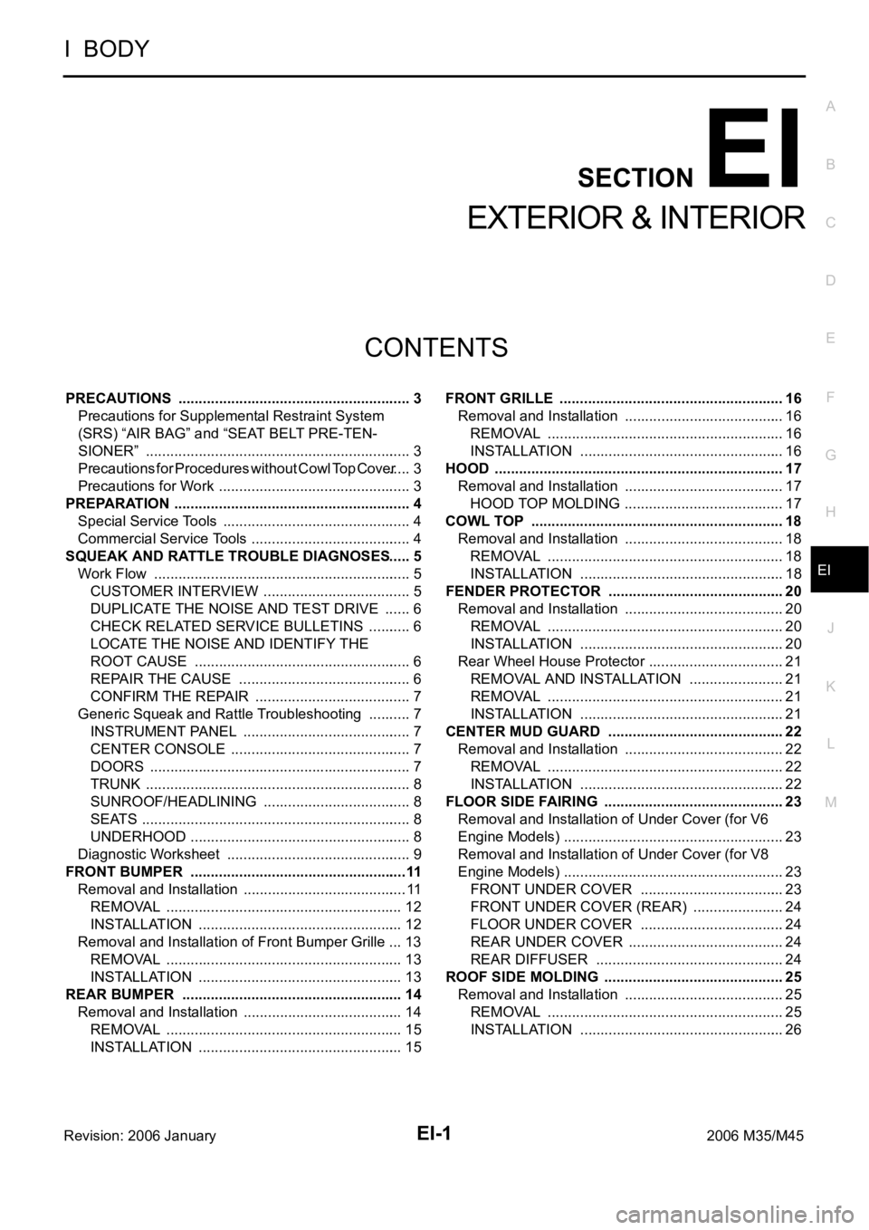
EI-1
EXTERIOR & INTERIOR
I BODY
CONTENTS
C
D
E
F
G
H
J
K
L
M
SECTION EI
A
B
EI
Revision: 2006 January2006 M35/M45
EXTERIOR & INTERIOR
PRECAUTIONS .......................................................... 3
Precautions for Supplemental Restraint System
(SRS) “AIR BAG” and “SEAT BELT PRE-TEN-
SIONER” .................................................................. 3
Precautions for Procedures without Cowl Top Cover ..... 3
Precautions for Work ...........................................
..... 3
PREPARATION ........................................................... 4
Special Service Tools ............................................... 4
Commercial Service Tools ........................................ 4
SQUEAK AND RATTLE TROUBLE DIAGNOSES ..... 5
Work Flow ................................................................ 5
CUSTOMER INTERVIEW ..................................... 5
DUPLICATE THE NOISE AND TEST DRIVE ....... 6
CHECK RELATED SERVICE BULLETINS ........... 6
LOCATE THE NOISE AND IDENTIFY THE
ROOT CAUSE ...................................................... 6
REPAIR THE CAUSE ........................................... 6
CONFIRM THE REPAIR ....................................... 7
Generic Squeak and Rattle Troubleshooting ........... 7
INSTRUMENT PANEL .......................................... 7
CENTER CONSOLE ............................................. 7
DOORS ................................................................. 7
TRUNK .................................................................. 8
SUNROOF/HEADLINING ..................................... 8
SEATS ................................................................... 8
UNDERHOOD ....................................................... 8
Diagnostic Worksheet .............................................. 9
FRONT BUMPER ......................................................11
Removal and Installation ......................................... 11
REMOVAL ........................................................
... 12
INSTALLATION ................................................... 12
Removal and Installation of Front Bumper Grille ... 13
REMOVAL ........................................................
... 13
INSTALLATION ................................................... 13
REAR BUMPER ....................................................
... 14
Removal and Installation ........................................ 14
REMOVAL ........................................................
... 15
INSTALLATION ................................................... 15FRONT GRILLE ........................................................ 16
Removal and Installation ........................................ 16
REMOVAL ........................................................
... 16
INSTALLATION ................................................... 16
HOOD ........................................................................ 17
Removal and Installation ........................................ 17
HOOD TOP MOLDING ........................................ 17
COWL TOP ............................................................... 18
Removal and Installation ........................................ 18
REMOVAL ........................................................
... 18
INSTALLATION ................................................
... 18
FENDER PROTECTOR ............................................ 20
Removal and Installation ........................................ 20
REMOVAL ........................................................
... 20
INSTALLATION ................................................... 20
Rear Wheel House Protector .................................. 21
REMOVAL AND INSTALLATION ........................ 21
REMOVAL ........................................................
... 21
INSTALLATION ................................................... 21
CENTER MUD GUARD ............................................ 22
Removal and Installation ........................................ 22
REMOVAL ........................................................
... 22
INSTALLATION ................................................... 22
FLOOR SIDE FAIRING ............................................. 23
Removal and Installation of Under Cover (for V6
Engine Models) ....................................................... 23
Removal and Installation of Under Cover (for V8
Engine Models) ....................................................... 23
FRONT UNDER COVER .................................... 23
FRONT UNDER COVER (REAR) ....................... 24
FLOOR UNDER COVER .................................... 24
REAR UNDER COVER ....................................... 24
REAR DIFFUSER ............................................... 24
ROOF SIDE MOLDING ............................................. 25
Removal and Installation ........................................ 25
REMOVAL ........................................................
... 25
INSTALLATION ................................................... 26
Page 3028 of 5621

FLOOR SIDE FAIRING
EI-23
C
D
E
F
G
H
J
K
L
MA
B
EI
Revision: 2006 January2006 M35/M45
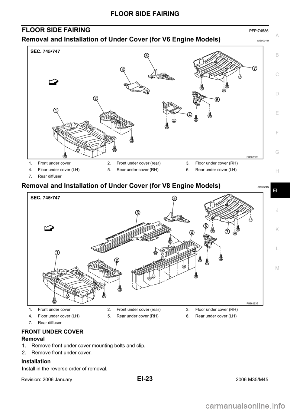
FLOOR SIDE FAIRINGPFP:74586
Removal and Installation of Under Cover (for V6 Engine Models)NIS0024M
Removal and Installation of Under Cover (for V8 Engine Models)NIS0024N
FRONT UNDER COVER
Removal
1. Remove front under cover mounting bolts and clip.
2. Remove front under cover.
Installation
Install in the reverse order of removal.
1. Front under cover 2. Front under cover (rear) 3. Floor under cover (RH)
4. Floor under cover (LH) 5. Rear under cover (RH) 6. Rear under cover (LH)
7. Rear diffuser
PIIB6282E
1. Front under cover 2. Front under cover (rear) 3. Floor under cover (RH)
4. Floor under cover (LH) 5. Rear under cover (RH) 6. Rear under cover (LH)
7. Rear diffuser
PIIB6283E
Page 3029 of 5621

EI-24
FLOOR SIDE FAIRING
Revision: 2006 January2006 M35/M45
FRONT UNDER COVER (REAR)
Removal
1. Remove front under cover (rear) mounting bolts.
2. Remove front under cover (rear).
Installation
Install in the reverse order of removal.
FLOOR UNDER COVER
Removal
1. Remove floor under cover mounting bolts, nuts and clips.
2. Remove floor under cover.
Installation
Install in the reverse order of removal.
REAR UNDER COVER
Removal
1. Remove rear under cover mounting bolts.
2. Remove rear under cover.
Installation
Install in the reverse order of removal.
REAR DIFFUSER
Removal
1. Remove rear diffuser mounting bolts, nuts and clips.
2. Remove rear diffuser.
Installation
Install in the reverse order of removal.
Page 3049 of 5621

EI-44
SUNSHADE
Revision: 2006 January2006 M35/M45
SUNSHADEPFP:97580
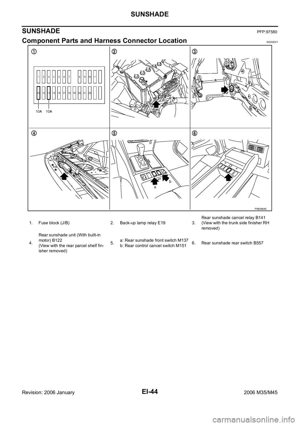
Component Parts and Harness Connector LocationNIS0024Y
PIIB5864E
1. Fuse block (J/B) 2. Back-up lamp relay E19 3.Rear sunshade cancel relay B141
(View with the trunk side finisher RH
removed)
4.Rear sunshade unit (With built-in
motor) B122
(View with the rear parcel shelf fin-
isher removed)5.a: Rear sunshade front switch M137
b: Rear control cancel switch M1516. Rear sunshade rear switch B557
Page 3111 of 5621
![INFINITI M35 2006 Factory Service Manual EM-48
[VQ35DE]
FUEL INJECTOR AND FUEL TUBE
Revision: 2006 January2006 M35/M45
Lubricate O-ring with new engine oil.
Do not clean O-ring with solvent.
Make sure that O-ring and its mating part are free INFINITI M35 2006 Factory Service Manual EM-48
[VQ35DE]
FUEL INJECTOR AND FUEL TUBE
Revision: 2006 January2006 M35/M45
Lubricate O-ring with new engine oil.
Do not clean O-ring with solvent.
Make sure that O-ring and its mating part are free](/manual-img/42/57023/w960_57023-3110.png)
EM-48
[VQ35DE]
FUEL INJECTOR AND FUEL TUBE
Revision: 2006 January2006 M35/M45
Lubricate O-ring with new engine oil.
Do not clean O-ring with solvent.
Make sure that O-ring and its mating part are free of foreign material.
When installing O-ring, be careful not to scratch it with tool or fingernails. Also be careful not
to twist or stretch O-ring. If O-ring was stretched while it was being attached, do not insert it
quickly into fuel tube.
Insert new O-ring straight into fuel tube. Do not decenter or twist it.
Insert fuel damper and fuel sub-tube straight into fuel tube.
Tighten mounting bolts evenly in turn.
After tightening mounting bolts, make sure that there is no gap between flange and fuel tube.
2. Install new O-rings to fuel injector, paying attention to the following.
CAUTION:
Upper and lower O-ring are different. Be careful not to confuse them.
Handle O-ring with bare hands. Do not wear gloves.
Lubricate O-ring with new engine oil.
Do not clean O-ring with solvent.
Make sure that O-ring and its mating part are free of foreign material.
When installing O-ring, be careful not to scratch it with tool or fingernails. Also be careful not to
twist or stretch O-ring. If O-ring was stretched while it was being attached, do not insert it
quickly into fuel tube.
Insert O-ring straight into fuel injector. Do not decenter or twist it.
3. Install fuel injector to fuel tube as follows:
a. Insert clip into clip mounting groove on fuel injector.
Insert clip so that protrusion “A” of fuel injector matches cutout
“A” of clip.
CAUTION:
Do not reuse clip. Replace it with a new one.
Be careful to keep clip from interfering with O-ring. If
interference occurs, replace O-ring.
b. Insert fuel injector into fuel tube with clip attached.
Insert it while matching it to the axial center.
Insert fuel injector so that protrusion “B” of fuel tube matches
cutout “B” of clip.
Make sure that fuel tube flange is securely fixed in flange fix-
ing groove on clip.
c. Make sure that installation is complete by checking that fuel
injector does not rotate or come off.
Make sure that protrusions of fuel injectors are aligned with
cutouts of clips after installation.
4. Install spacers on intake manifold.
5. Install fuel tube and fuel injector assembly to intake manifold.
CAUTION:
Be careful not to let tip of injector nozzle come in contact with other parts. Fuel tube side : Black
Nozzle side : Green
PBIC2545E