2006 INFINITI M35 turn signals
[x] Cancel search: turn signalsPage 4566 of 5621

ACTIVE AFS
LT-139
C
D
E
F
G
H
I
J
L
MA
B
LT
Revision: 2006 January2006 M35/M45
HEADLAMP AUTO AIMING OPERATION
The height sensor detects a change in height of rear vehicle with ignition switch ON, and transmits signals to
the AFS control unit:
When ignition switch is turn to ON position, power is supplied
to height sensor terminal 1
through AFS control unit terminal 6.
When ignition switch is turned to ON position, height sensor input signal is supplied
to AFS control unit terminal 28
through height sensor terminal 2.
Ground is supplied
to height sensor terminal 3
through AFS control unit terminal 8.
Aiming motor driving signal (voltage signal that corresponds to the vehicle height) is transmitted depending on
the height sensor signal at the start of the engine
to front combination lamp LH terminal 12
through AFS control unit terminal 40,
to front combination lamp RH terminal 12
through AFS control unit terminal 19.
Output of aiming motor driving signal is maintained unless headlamp (HIGH/LOW) illuminate detected.
Auto aiming control operation starts when headlamps (HIGH/LOW) illuminate detected.
When headlamps (HIGH/LOW) illuminate, output of aiming motor driving signal is changed according to the
height sensor signal. After the change, it is changed according to height sensor signals with predetermined
timing based on driving condition while headlamps are ON.
Auto Aiming Operation
AFS control unit starts outputting aiming motor drive signal when the engine starts, and continues to output it
until the engine stops. Aiming motor drive signal changes output when the specified conditions described
below are met.
Headlamp aiming motors set the low beam projectors according to aiming motor drive signals received from
AFS control unit, both headlamp aiming motors cause the low beam projectors to move to the position com-
manded by the signal.
The aiming motor drive signal level retains when the following conditions are not met.
AFS control unit operation when the vehicle is stopped (low beam headlamps illuminated)
Headlamp aiming motor drive signal is changed when vehicle height is stabilized with a parked condition,
depending on the height sensor signal detected with height sensor signal by AFS control unit.
AFS control unit operation when the vehicle is running (low beam headlamps illuminated)
When vehicle is running, headlamp aiming motor drive signal is changed depending on the height sensor
signal which is detected when AFS control unit detects constant steady speed of vehicle.
When the vehicle is accelerating or decelerating, AFS control unit keeps headlamp aiming motor drive sig-
nal voltage level rather than changing it, so that the low beam projectors of both headlamps do not oper-
ate.
CAN COMMUNICATION SYSTEM DESCRIPTION
CAN (Controller Area Network) is a serial communication line for real time application. It is an on-vehicle mul-
tiplex communication line with high data communication speed and excellent error detection ability. Many elec-
tronic control units are equipped onto a vehicle, and each control unit shares information and links with other
control units during operation (not independent). In CAN communication, control units are connected with 2
communication lines (CAN H line, CAN L line) allowing a high rate of information transmission with less wiring.
Each control unit transmits/receives data but selectively reads required data only.
CAN COMMUNICATION UNIT
Refer to LAN-34, "CAN Communication Unit" .
Page 4568 of 5621

ACTIVE AFS
LT-141
C
D
E
F
G
H
I
J
L
MA
B
LT
Revision: 2006 January2006 M35/M45
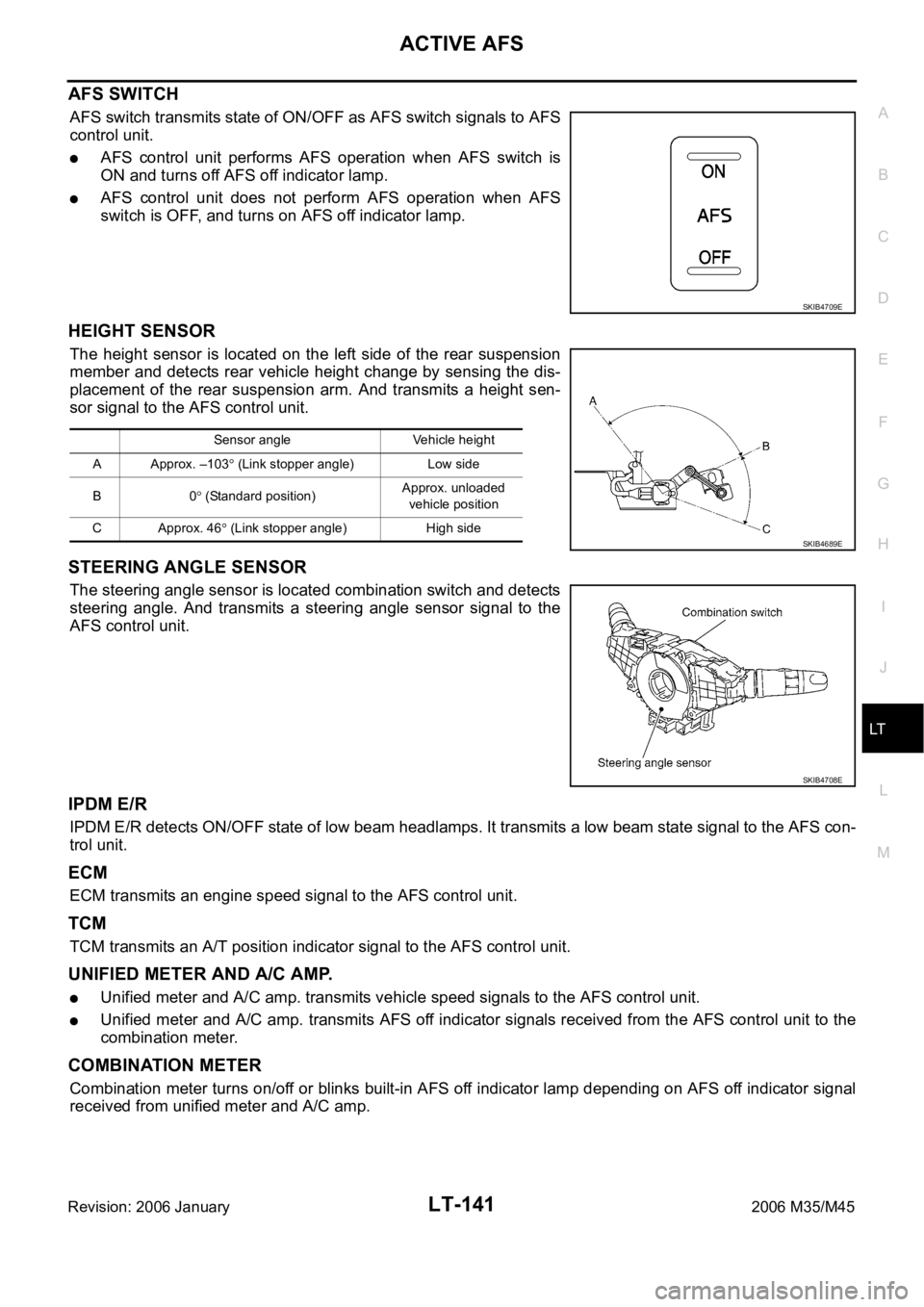
AFS SWITCH
AFS switch transmits state of ON/OFF as AFS switch signals to AFS
control unit.
AFS control unit performs AFS operation when AFS switch is
ON and turns off AFS off indicator lamp.
AFS control unit does not perform AFS operation when AFS
switch is OFF, and turns on AFS off indicator lamp.
HEIGHT SENSOR
The height sensor is located on the left side of the rear suspension
member and detects rear vehicle height change by sensing the dis-
placement of the rear suspension arm. And transmits a height sen-
sor signal to the AFS control unit.
STEERING ANGLE SENSOR
The steering angle sensor is located combination switch and detects
steering angle. And transmits a steering angle sensor signal to the
AFS control unit.
IPDM E/R
IPDM E/R detects ON/OFF state of low beam headlamps. It transmits a low beam state signal to the AFS con-
trol unit.
ECM
ECM transmits an engine speed signal to the AFS control unit.
TCM
TCM transmits an A/T position indicator signal to the AFS control unit.
UNIFIED METER AND A/C AMP.
Unified meter and A/C amp. transmits vehicle speed signals to the AFS control unit.
Unified meter and A/C amp. transmits AFS off indicator signals received from the AFS control unit to the
combination meter.
COMBINATION METER
Combination meter turns on/off or blinks built-in AFS off indicator lamp depending on AFS off indicator signal
received from unified meter and A/C amp.
SKIB4709E
Sensor angle Vehicle height
A Approx. –103
(Link stopper angle) Low side
B0
(Standard position)Approx. unloaded
vehicle position
C Approx. 46
(Link stopper angle) High side SKIB4689E
SKIB4708E
Page 4585 of 5621

LT-158
ACTIVE AFS
Revision: 2006 January2006 M35/M45
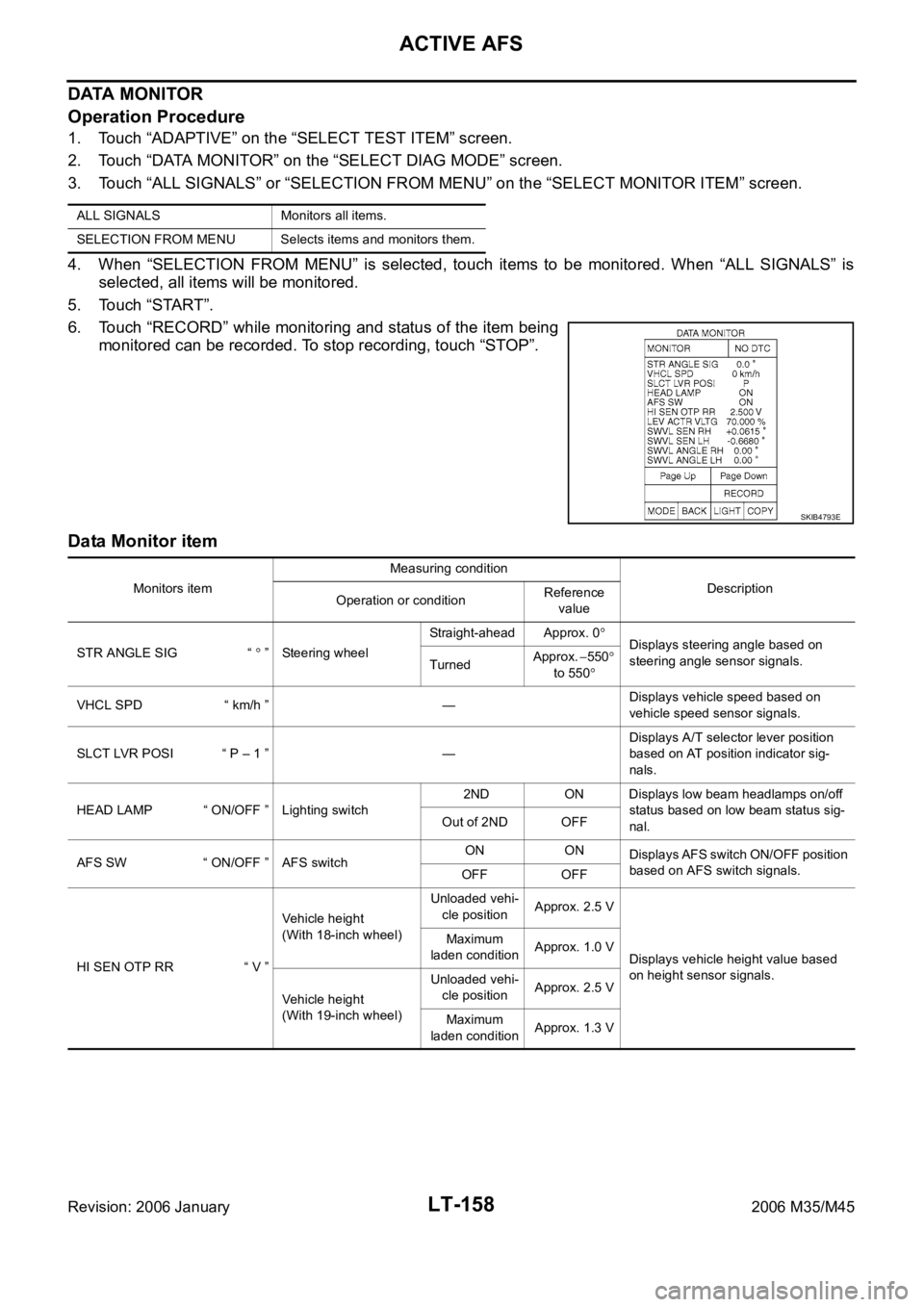
DATA MONITOR
Operation Procedure
1. Touch “ADAPTIVE” on the “SELECT TEST ITEM” screen.
2. Touch “DATA MONITOR” on the “SELECT DIAG MODE” screen.
3. Touch “ALL SIGNALS” or “SELECTION FROM MENU” on the “SELECT MONITOR ITEM” screen.
4. When “SELECTION FROM MENU” is selected, touch items to be monitored. When “ALL SIGNALS” is
selected, all items will be monitored.
5. Touch “START”.
6. Touch “RECORD” while monitoring and status of the item being
monitored can be recorded. To stop recording, touch “STOP”.
Data Monitor item
ALL SIGNALS Monitors all items.
SELECTION FROM MENU Selects items and monitors them.
SKIB4793E
Monitors itemMeasuring condition
Description
Operation or conditionReference
value
STR ANGLE SIG “
” Steering wheelStraight-ahead Approx. 0Displays steering angle based on
steering angle sensor signals.
TurnedApprox. 550
to 550
VHCL SPD “ km/h ” —Displays vehicle speed based on
vehicle speed sensor signals.
SLCT LVR POSI “ P – 1 ” —Displays A/T selector lever position
based on AT position indicator sig-
nals.
HEAD LAMP “ ON/OFF ” Lighting switch 2ND ON Displays low beam headlamps on/off
status based on low beam status sig-
nal. Out of 2ND OFF
AFS SW “ ON/OFF ” AFS switchON ON
Displays AFS switch ON/OFF position
based on AFS switch signals.
OFF OFF
HI SEN OTP RR “ V ”Vehicle height
(With 18-inch wheel)Unloaded vehi-
cle positionApprox. 2.5 V
Displays vehicle height value based
on height sensor signals. Maximum
laden conditionApprox. 1.0 V
Vehicle height
(With 19-inch wheel)Unloaded vehi-
cle positionApprox. 2.5 V
Maximum
laden conditionApprox. 1.3 V
Page 4639 of 5621

LT-212
TURN SIGNAL AND HAZARD WARNING LAMPS
Revision: 2006 January2006 M35/M45
LH Turn Signal Lamp
When turn signal switch is moved to left position, BCM receives input signal requesting left turn signals to
flash. BCM then supplies power
through BCM terminal 45
to front combination lamp LH (turn signal) terminal 10
to side turn signal lamp LH terminal 1, and
to rear combination lamp LH (turn signal) terminal 3.
Ground is supplied
to front combination lamp LH (turn signal) terminal 9
to side turn signal lamp LH terminal 2
through grounds E22 and E43,
to rear combination lamp LH (turn signal) terminal 4
through grounds B5, B40 and B131.
The BCM also supplies input to unified meter and A/C amp. terminals 56 and 72 across the CAN communica-
tion lines.
The unified meter and A/C amp. which received the turn indicator signal makes the left turn signal indicator
turn on in combination meter.
With power and input supplied, the BCM controls the flashing of the LH turn signal lamps.
RH Turn Signal Lamp
When turn signal switch is moved to right position, BCM receives input signal requesting right turn signals to
flash. BCM then supplies power
through BCM terminal 46
to front combination lamp RH (turn signal) terminal 10
to side turn signal lamp RH terminal 1, and
to rear combination lamp RH (turn signal) terminal 3.
Ground is supplied
to front combination lamp RH (turn signal) terminal 9
to side turn signal lamp RH terminal 2
through grounds E22 and E43,
to rear combination lamp RH (turn signal) terminal 4
through grounds B5, B40 and B131.
The BCM also supplies input to unified meter and A/C amp. terminals 56 and 72 across the CAN communica-
tion lines.
The unified meter and A/C amp. which received the turn indicator signal makes the right turn signal indicator
turn on in combination meter.
With power and input supplied, the BCM controls the flashing of the RH turn signal lamps.
HAZARD LAMP OPERATION
Power is supplied at all times
through 50A fusible link (letter F, located in fuse, fusible link and relay block)
to BCM terminal 55,
through 10A fuse [No. 21, located in fuse block (J/B)]
to BCM terminal 42
to combination meter terminal 23,
through 10A fuse [No. 19, located in fuse block (J/B)]
to unified meter and A/C amp. terminal 54.
When the hazard switch is depressed, ground is supplied
to BCM terminal 29
through multifunction switch terminal 6.
Ground is supplied
to multifunction switch terminal 14
Page 4651 of 5621

LT-224
TURN SIGNAL AND HAZARD WARNING LAMPS
Revision: 2006 January2006 M35/M45
DATA MONITOR
Operation Procedure
1. Touch “FLASHER” on “SELECT TEST ITEM” screen.
2. Touch “DATA MONITOR” on “SELECT DIAG MODE” screen.
3. Touch either “ALL SIGNALS” or “SELECTION FROM MENU” on the “SELECT MONITOR ITEM” screen.
4. When “SELECTION FROM MENU” is selected, touch items to be monitored. When “ALL SIGNALS” is
selected, all the items will be monitored.
5. Touch “START”.
6. Touch “RECORD” while monitoring, then the status of the monitored item can be recorded. To stop
recording, touch “STOP”.
Display Item List
ACTIVE TEST
Operation Procedure
1. Touch “FLASHER” on “SELECT TEST ITEM” screen.
2. Touch “ACTIVE TEST” on “SELECT DIAG MODE” screen.
3. Touch item to be tested and check operation of the selected item.
4. During the operation check, touching “BACK” deactivates the operation.
Display Item List
ALL SIGNALS Monitors all the signals.
SELECTION FROM MENU Selects items and monitor them.
Monitor item Contents
IGN ON SW “ON/OFF” Displays “IGN position (ON)/OFF, ACC position (OFF)” judged from the ignition switch signal.
HAZARD SW “ON/OFF” Displays “hazard ON (ON)/hazard OFF (OFF)” status, determined from hazard switch signal.
TURN SIGNAL R “ON/OFF” Displays “turn right (ON)/other (OFF)” status, determined from lighting switch signal.
TURN SIGNAL L “ON/OFF” Displays “turn left (ON)/other (OFF)” status, determined from lighting switch signal.
Test item Description
FLASHER (RIGHT) Turn signal lamp (right) can be operated by any ON-OFF operations.
FLASHER (LEFT) Turn signal lamp (left) can be operated by any ON-OFF operations.
Page 4666 of 5621

COMBINATION SWITCH
LT-239
C
D
E
F
G
H
I
J
L
MA
B
LT
Revision: 2006 January2006 M35/M45
DATA MONITOR
Operation Procedure
1. Touch “COMB SW” on “SELECT TEST ITEM” screen.
2. Touch “DATA MONITOR” on “SELECT DIAG MODE” screen.
3. Touch either “ALL SIGNALS” or “SELECTION FROM MENU” on “SELECT MONITOR ITEM” screen.
4. When “SELECTION FROM MENU” is selected, touch items to be monitored. When “ALL SIGNALS” is
selected, all the signals will be monitored.
5. Touch “START”.
6. Touch “RECORD” while monitoring, then the status of the monitored item can be recorded. To stop
recording, touch “STOP”.
Display Item List
ALL SIGNALS Monitors all the signals.
SELECTION FROM MENU Selects items and monitor them.
Monitor item name Contents
TURN SIGNAL R “ON/OFF” Displays “turn right (ON)/other (OFF)” status, determined from lighting switch signal.
TURN SIGNAL L “ON/OFF” Displays “turn left (ON)/other (OFF)” status, determined from lighting switch signal.
HI BEAM SW “ON/OFF”Displays status (high beam switch: ON/others: OFF) of high beam switch judged from lighting
switch signal.
HEAD LAMP SW 1 “ON/OFF”Displays status (headlamp switch 1: ON/others: OFF) of headlamp switch 1 judged from lighting
switch signal.
HEAD LAMP SW 2 “ON/OFF”Displays status (headlamp switch 2: ON/others: OFF) of headlamp switch 2 judged from lighting
switch signal.
TAIL LAMP SW “ON/OFF”Displays status (lighting switch 1ST or 2ND position: ON/others: OFF) of lighting switch judged from
lighting switch signal.
PASSING SW “ON/OFF”Displays status (flash-to-pass switch: ON/others: OFF) of flash-to-pass switch judged from lighting
switch signal.
AUTO LIGHT SW “ON/OFF” Displays “auto light switch (ON)/other (OFF)” status, determined from lighting switch signal.
FR FOG SW “ON/OFF” Displays “front fog lamp switch (ON)/other (OFF)” status, determined from lighting switch signal.
FR WIPER HI “ON/OFF” Displays “front wiper HI (ON)/other (OFF)” status, determined from wiper switch signal.
FR WIPER LOW “ON/OFF” Displays “front wiper LOW (ON)/other (OFF)” status, determined from wiper switch signal.
FR WIPER INT “ON/OFF” Displays “front wiper INT (ON)/other (OFF)” status, determined from wiper switch signal.
FR WASHER SW “ON/OFF” Displays “front washer switch (ON)/other (OFF)” status, determined from wiper switch signal.
INT VOLUME “1 - 7” Displays intermittent operation knob setting (1 - 7), determined from wiper switch signal.
Page 4694 of 5621

INTERIOR ROOM LAMP
LT-267
C
D
E
F
G
H
I
J
L
MA
B
LT
Revision: 2006 January2006 M35/M45
INTERIOR ROOM LAMPPFP:26410
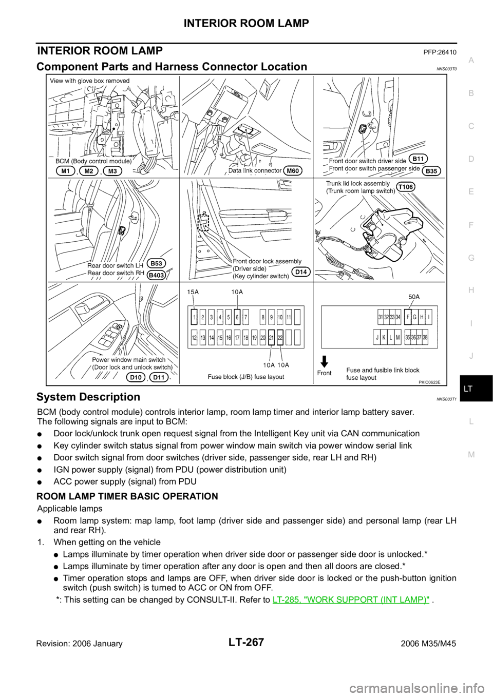
Component Parts and Harness Connector LocationNKS003T0
System DescriptionNKS003T1
BCM (body control module) controls interior lamp, room lamp timer and interior lamp battery saver.
The following signals are input to BCM:
Door lock/unlock trunk open request signal from the Intelligent Key unit via CAN communication
Key cylinder switch status signal from power window main switch via power window serial link
Door switch signal from door switches (driver side, passenger side, rear LH and RH)
IGN power supply (signal) from PDU (power distribution unit)
ACC power supply (signal) from PDU
ROOM LAMP TIMER BASIC OPERATION
Applicable lamps
Room lamp system: map lamp, foot lamp (driver side and passenger side) and personal lamp (rear LH
and rear RH).
1. When getting on the vehicle
Lamps illuminate by timer operation when driver side door or passenger side door is unlocked.*
Lamps illuminate by timer operation after any door is open and then all doors are closed.*
Timer operation stops and lamps are OFF, when driver side door is locked or the push-button ignition
switch (push switch) is turned to ACC or ON from OFF.
*: This setting can be changed by CONSULT-II. Refer to LT- 2 8 5 , "
WORK SUPPORT (INT LAMP)" .
PKIC0623E
Page 4698 of 5621

INTERIOR ROOM LAMP
LT-271
C
D
E
F
G
H
I
J
L
MA
B
LT
Revision: 2006 January2006 M35/M45
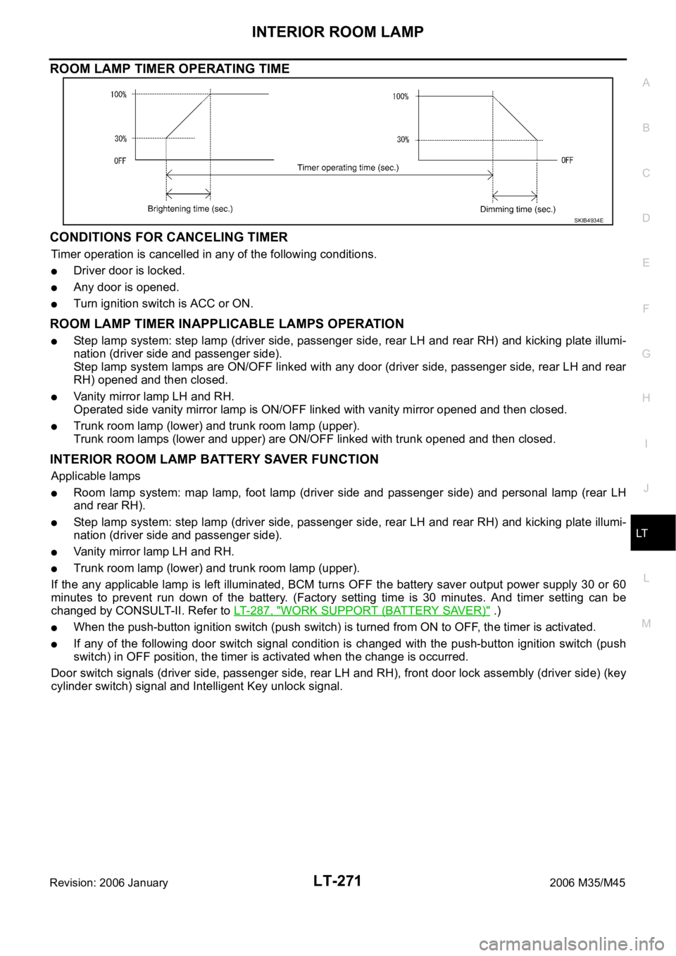
ROOM LAMP TIMER OPERATING TIME
CONDITIONS FOR CANCELING TIMER
Timer operation is cancelled in any of the following conditions.
Driver door is locked.
Any door is opened.
Turn ignition switch is ACC or ON.
ROOM LAMP TIMER INAPPLICABLE LAMPS OPERATION
Step lamp system: step lamp (driver side, passenger side, rear LH and rear RH) and kicking plate illumi-
nation (driver side and passenger side).
Step lamp system lamps are ON/OFF linked with any door (driver side, passenger side, rear LH and rear
RH) opened and then closed.
Vanity mirror lamp LH and RH.
Operated side vanity mirror lamp is ON/OFF linked with vanity mirror opened and then closed.
Trunk room lamp (lower) and trunk room lamp (upper).
Trunk room lamps (lower and upper) are ON/OFF linked with trunk opened and then closed.
INTERIOR ROOM LAMP BATTERY SAVER FUNCTION
Applicable lamps
Room lamp system: map lamp, foot lamp (driver side and passenger side) and personal lamp (rear LH
and rear RH).
Step lamp system: step lamp (driver side, passenger side, rear LH and rear RH) and kicking plate illumi-
nation (driver side and passenger side).
Vanity mirror lamp LH and RH.
Trunk room lamp (lower) and trunk room lamp (upper).
If the any applicable lamp is left illuminated, BCM turns OFF the battery saver output power supply 30 or 60
minutes to prevent run down of the battery. (Factory setting time is 30 minutes. And timer setting can be
changed by CONSULT-II. Refer to LT-287, "
WORK SUPPORT (BATTERY SAVER)" .)
When the push-button ignition switch (push switch) is turned from ON to OFF, the timer is activated.
If any of the following door switch signal condition is changed with the push-button ignition switch (push
switch) in OFF position, the timer is activated when the change is occurred.
Door switch signals (driver side, passenger side, rear LH and RH), front door lock assembly (driver side) (key
cylinder switch) signal and Intelligent Key unlock signal.
SKIB4934E