2006 INFINITI M35 battery
[x] Cancel search: batteryPage 1056 of 5621
INTELLIGENT KEY SYSTEM
BL-117
C
D
E
F
G
H
J
K
L
MA
B
BL
Revision: 2006 January2006 M35/M45
Check Ignition Switch PositionNIS001XY
1. CHECK IGNITION POWER SUPPLY
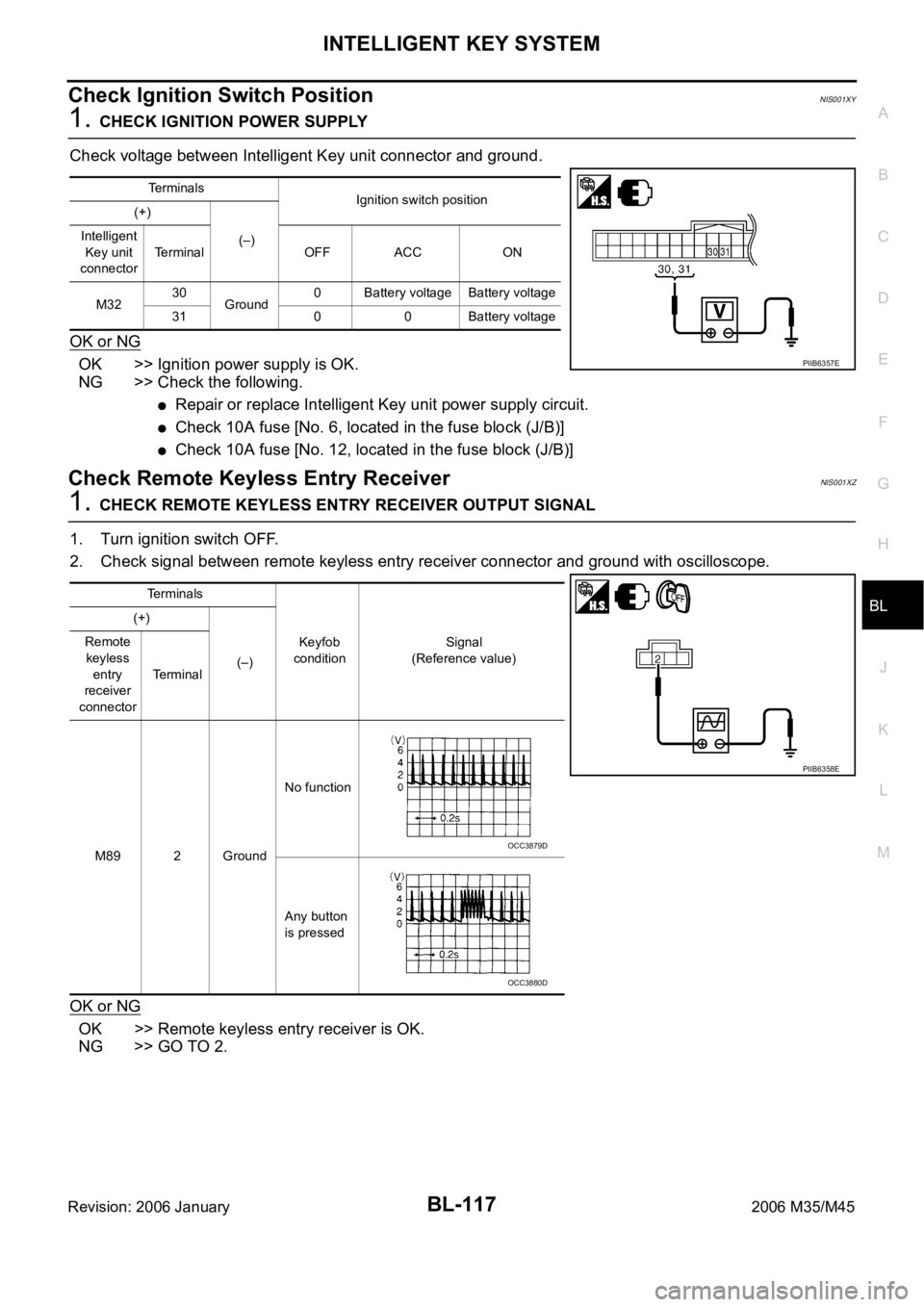
Check voltage between Intelligent Key unit connector and ground.
OK or NG
OK >> Ignition power supply is OK.
NG >> Check the following.
Repair or replace Intelligent Key unit power supply circuit.
Check 10A fuse [No. 6, located in the fuse block (J/B)]
Check 10A fuse [No. 12, located in the fuse block (J/B)]
Check Remote Keyless Entry ReceiverNIS001XZ
1. CHECK REMOTE KEYLESS ENTRY RECEIVER OUTPUT SIGNAL
1. Turn ignition switch OFF.
2. Check signal between remote keyless entry receiver connector and ground with oscilloscope.
OK or NG
OK >> Remote keyless entry receiver is OK.
NG >> GO TO 2.
Te r m i n a l s
Ignition switch position
(+)
(–) Intelligent
Key unit
connectorTerminal OFF ACC ON
M3230
Ground0 Battery voltage Battery voltage
31 0 0 Battery voltage
PIIB6357E
Terminals
Keyfob
conditionSignal
(Reference value) (+)
(–) Remote
keyless
entry
receiver
connectorTerminal
M89 2 GroundNo function
Any button
is pressed
PIIB6358E
OCC3879D
OCC3880D
Page 1062 of 5621
INTELLIGENT KEY SYSTEM
BL-123
C
D
E
F
G
H
J
K
L
MA
B
BL
Revision: 2006 January2006 M35/M45
Check Key Slot IlluminationNIS001Y1
1. CHECK KEY SLOT ILLUMINATION OUTPUT SIGNAL
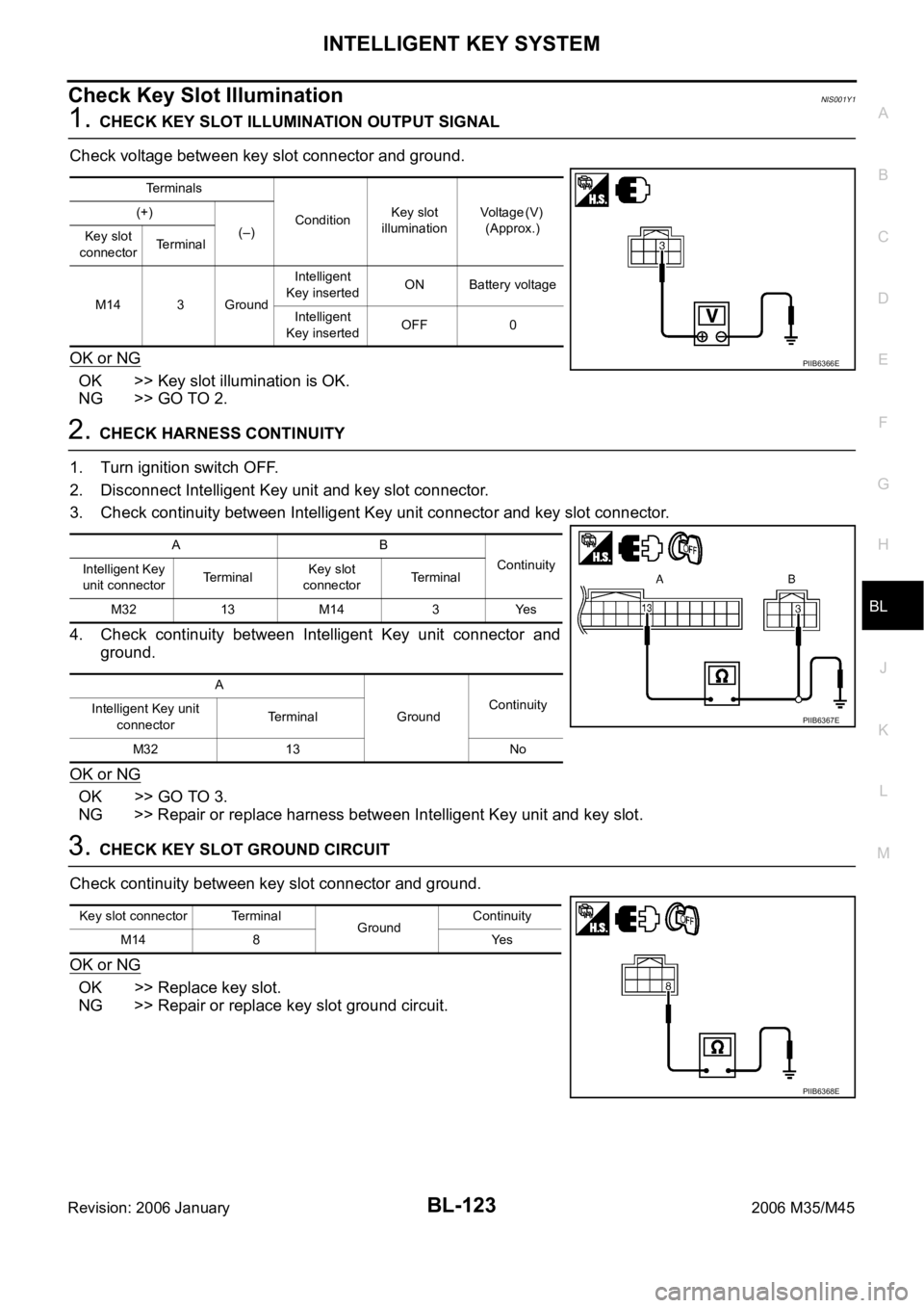
Check voltage between key slot connector and ground.
OK or NG
OK >> Key slot illumination is OK.
NG >> GO TO 2.
2. CHECK HARNESS CONTINUITY
1. Turn ignition switch OFF.
2. Disconnect Intelligent Key unit and key slot connector.
3. Check continuity between Intelligent Key unit connector and key slot connector.
4. Check continuity between Intelligent Key unit connector and
ground.
OK or NG
OK >> GO TO 3.
NG >> Repair or replace harness between Intelligent Key unit and key slot.
3. CHECK KEY SLOT GROUND CIRCUIT
Check continuity between key slot connector and ground.
OK or NG
OK >> Replace key slot.
NG >> Repair or replace key slot ground circuit.
Terminals
ConditionKey slot
illuminationV o l t a g e ( V )
(Approx.) (+)
(–)
Key slot
connectorTe r m i n a l
M14 3 GroundIntelligent
Key insertedON Battery voltage
Intelligent
Key insertedOFF 0
PIIB6366E
AB
Continuity
Intelligent Key
unit connectorTe r m i n a lKey slot
connectorTe r m i n a l
M32 13 M14 3 Yes
A
GroundContinuity
Intelligent Key unit
connectorTerminal
M32 13 No
PIIB6367E
Key slot connector Terminal
GroundContinuity
M14 8 Yes
PIIB6368E
Page 1063 of 5621
BL-124
INTELLIGENT KEY SYSTEM
Revision: 2006 January2006 M35/M45
Check Horn FunctionNIS001Y2
First perform the “SELF-DIAG RESULTS” of “BCM” with CONSULT-II, then perform the trouble diagno-
sis of malfunction system indicated in “SELF-DIAG RESULTS” of “BCM”. Refer to BCS-15, "
CAN Com-
munication Inspection Using CONSULT-II (Self-Diagnosis)".
1. CHECK HORN OPERATION
Check if horn sounds with horn switch.
Does horn operate?
Yes >> GO TO 2.
No >> Check horn circuit. Refer to WW-53, "
HORN" .
2. CHECK IPDM E/R INPUT SIGNAL
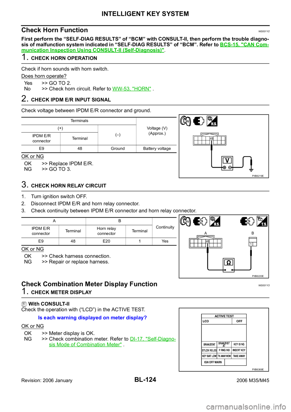
Check voltage between IPDM E/R connector and ground.
OK or NG
OK >> Replace IPDM E/R.
NG >> GO TO 3.
3. CHECK HORN RELAY CIRCUIT
1. Turn ignition switch OFF.
2. Disconnect IPDM E/R and horn relay connector.
3. Check continuity between IPDM E/R connector and horn relay connector.
OK or NG
OK >> Check harness connection.
NG >> Repair or replace harness.
Check Combination Meter Display FunctionNIS001Y3
1. CHECK METER DISPLAY
With CONSULT-II
Check the operation with (“LCD”) in the ACTIVE TEST.
OK or NG
OK >> Meter display is OK.
NG >> Check combination meter. Refer to DI-17, "
Self-Diagno-
sis Mode of Combination Meter" .
Terminals
Voltage (V)
(Approx.) (+)
(–)
IPDM E/R
connectorTerminal
E9 48 Ground Battery voltage
PIIB6219E
AB
Continuity
IPDM E/R
connectorTe r m i n a lHorn relay
connectorTerminal
E9 48 E20 1 Yes
PIIB6220E
Is each warning displayed on meter display?
PIIB6369E
Page 1065 of 5621
BL-126
INTELLIGENT KEY SYSTEM
Revision: 2006 January2006 M35/M45
Intelligent Key Battery ReplacementNIS001Y6
DISASSEMBLY AND ASSEMBLY OF INTELLIGENT KEY
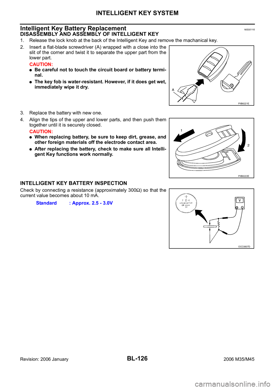
1. Release the lock knob at the back of the Intelligent Key and remove the machanical key.
2. Insert a flat-blade screwdriver (A) wrapped with a close into the
slit of the corner and twist it to separate the upper part from the
lower part.
CAUTION:
Be careful not to touch the circuit board or battery termi-
nal.
The key fob is water-resistant. However, if it does get wet,
immediately wipe it dry.
3. Replace the battery with new one.
4. Align the tips of the upper and lower parts, and then push them
together until it is securely closed.
CAUTION:
When replacing battery, be sure to keep dirt, grease, and
other foreign materials off the electrode contact area.
After replacing the battery, check to make sure all Intelli-
gent Key functions work normally.
INTELLIGENT KEY BATTERY INSPECTION
Check by connecting a resistance (approximately 300) so that the
current value becomes about 10 mA.
PIIB6221E
PIIB6222E
Standard : Approx. 2.5 - 3.0V
OCC0607D
Page 1067 of 5621
BL-128
INTELLIGENT KEY SYSTEM/ENGINE START FUNCTION
Revision: 2006 January2006 M35/M45
System DescriptionNIS001Y8
The engine start function of Intelligent Key system is a system that makes it possible to start and stop the
engine without removing the key. It verifies the electronic ID using two-way communications when press-
ing the push-button ignition switch while carrying the Intelligent Key, which operates based on the results
of electronic ID verification for Intelligent Key using two-way communications between the Intelligent Key
and the vehicle (Intelligent Key unit).
NOTE:
The driver should always carry the intelligent key at all times.
Intelligent Key has 2 IDs (for Intelligent Key and for immobilizer). It can perform the door lock/unlock oper-
ation and the push-button ignition switch operation when carrying the registered Intelligent Key.
When the Intelligent Key battery is discharged, it can be used as emergency by inserting the Intelligent
Key to the key slot. At that time, perform the immobilizer ID verification. If it is used when carrying the
Intelligent Key, perform the Intelligent Key ID verification.
If the ID is successfully verified, and when push-button ignition switch is pressed, steering lock will be
released and initiating the engine will be possible.
If the door lock/unlock operation is performed when the Intelligent Key battery is discharged, all doors
lock/unlock can be performed by operating the driver door key cylinder using the mechanical key set into
the Intelligent Key.
Intelligent Key can be registered up to 4 keys (Including the standard Intelligent Key) on request from the
owner.
NOTE:
Refer to BL-44, "INTELLIGENT KEY SYSTEM" for any functions other than engine start function of
Intelligent Key system.
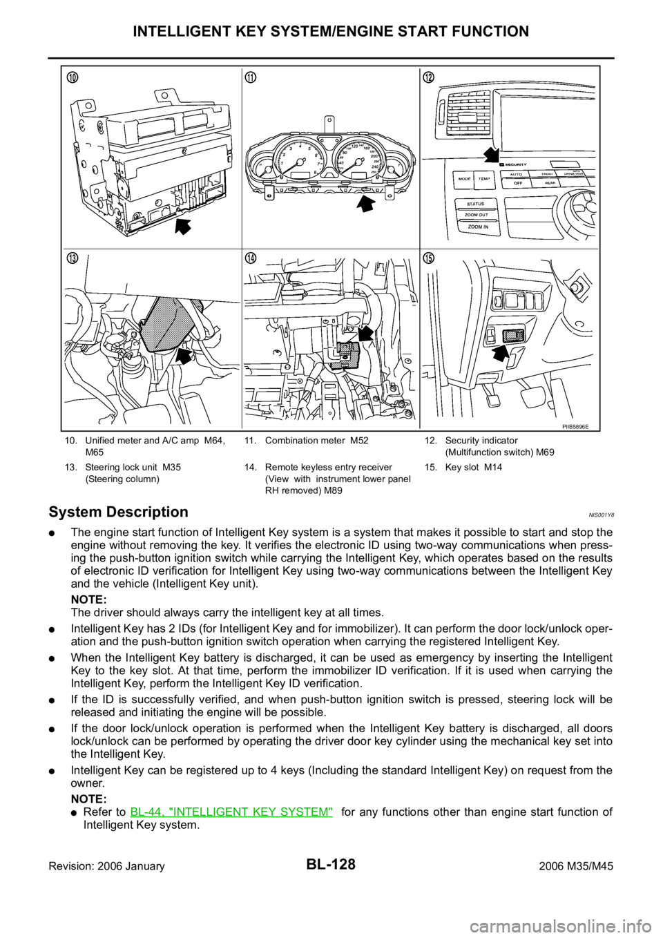
10. Unified meter and A/C amp M64,
M6511. Combination meter M52 12. Security indicator
(Multifunction switch) M69
13. Steering lock unit M35
(Steering column)14. Remote keyless entry receiver
(View with instrument lower panel
RH removed) M89 15. Key slot M14
PIIB5896E
Page 1069 of 5621

BL-130
INTELLIGENT KEY SYSTEM/ENGINE START FUNCTION
Revision: 2006 January2006 M35/M45
starter motor relay. (If the engine initiating has failed, the cranking will stop automatically within 5 sec-
onds.)
CAUTION:
When the Intelligent Key is carried outside of the vehicle (inside key antenna detection area) with
the power supply in ACC or ON position, even if the engine start condition* is satisfied, the engine
cannot be started.
*: For the engine start condition, refer to BL-130, "
PUSH-BUTTON IGNITION SWITCH OPERATION PROCE-
DURE" .
Operation Range
Engine can be started when Intelligent Key is inside the vehicle. However, sometimes engine might not start
when Intelligent Key is on instrument panel or in glove box.
OPERATION WHEN KEY SLOT IS USED
When the Intelligent Key battery is discharged, it performs the immobilizer ID verification between the inte-
grated transponder and BCM by inserting the Intelligent Key into the key slot, and then the engine can be
started.
For details relating to starting the engine using key slot, refer to BL-248, "
IVIS (INFINITI VEHICLE IMMOBI-
LIZER SYSTEM-NATS)" .
PUSH-BUTTON IGNITION SWITCH OPERATION PROCEDURE
The power supply position changing operation can be performed with the following operation.
NOTE:
When an Intelligent Key is within the detection area of inside key antenna and when it is inserted to the
key slot, it is equivalent to the operations below.
When starting the engine, the Intelligent Key unit monitors the engine start conditions (brake pedal operat-
ing condition, A/T selector lever position, and vehicle speed).
Unless each start condition is fulfilled, the engine will not respond regardless of how many times the
engine switch is pushed. At that time, illumination repeats the position in the order of LOCK
AC-
C
ONLOCK.
Power supply positionEngine start/stop condition
Push-button ignition switch
operation frequency
Brake pedal A/T selector lever position
LOCK
ACCNot depressed
(When A/T selector lever is in any
position other than P or N, there
will be no effect even if it is
depressed.)Any position other than P or N
(When the brake pedal is not
depressed, there will be no effect
even if the A/T selector lever is in
P or N position.)1
LOCK
ACC ONNot depressed
(When A/T selector lever is in any
position other than P or N, there
will be no effect even if it is
depressed.)Any position other than P or N
(When the brake pedal is not
depressed, there will be no effect
even if the A/T selector lever is in
P or N position.)2
LOCK
ACC ON
LOCKNot depressed
(When A/T selector lever is in any
position other than P or N, there
will be no effect even if it is
depressed.)Any position other than P or N
(When the brake pedal is not
depressed, there will be no effect
even if the A/T selector lever is in
P or N position.)3
LOCK
START
ACC
START
ON
START
(Engine start)Depressed P or N position (*1)1
[If the switch is pushed once,
the engine starts from any
power supply position (LOCK,
ACC, and ON)]
Engine is running
LOCK
(Engine stop)— P position 1
Page 1082 of 5621
INTELLIGENT KEY SYSTEM/ENGINE START FUNCTION
BL-143
C
D
E
F
G
H
J
K
L
MA
B
BL
Revision: 2006 January2006 M35/M45
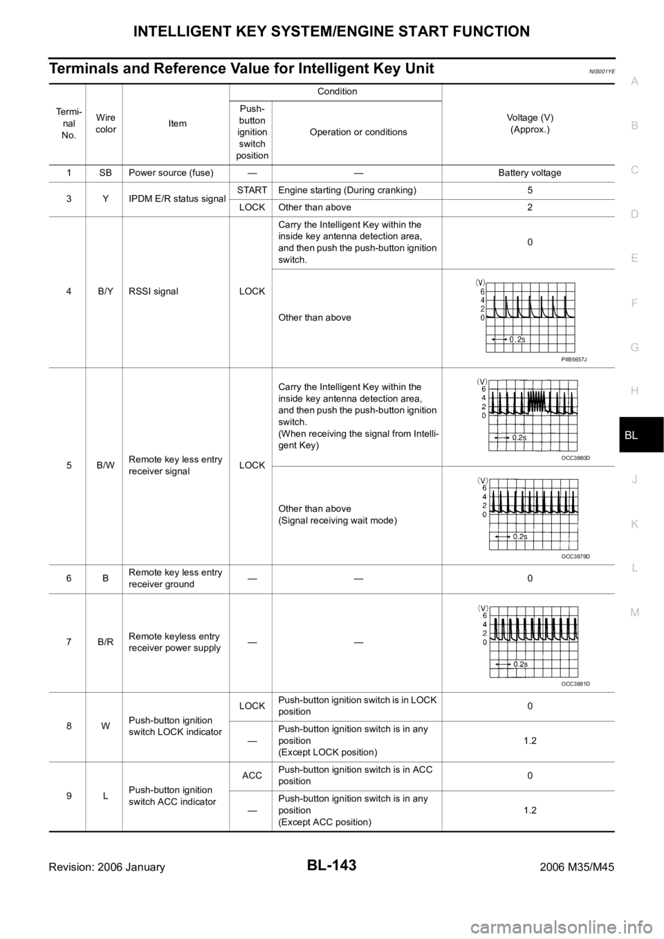
Terminals and Reference Value for Intelligent Key UnitNIS001YE
Te r m i -
nal
No.Wire
colorItemCondition
Voltage (V)
(Approx.) Push-
button
ignition
switch
positionOperation or conditions
1 SB Power source (fuse) — — Battery voltage
3 Y IPDM E/R status signalSTART Engine starting (During cranking) 5
LOCK Other than above 2
4 B/Y RSSI signal LOCKCarry the Intelligent Key within the
inside key antenna detection area,
and then push the push-button ignition
switch.0
Other than above
5B/WRemote key less entry
receiver signalLOCKCarry the Intelligent Key within the
inside key antenna detection area,
and then push the push-button ignition
switch.
(When receiving the signal from Intelli-
gent Key)
Other than above
(Signal receiving wait mode)
6BRemote key less entry
receiver ground—— 0
7B/RRemote keyless entry
receiver power supply——
8WPush-button ignition
switch LOCK indicatorLOCKPush-button ignition switch is in LOCK
position0
—Push-button ignition switch is in any
position
(Except LOCK position)1.2
9LPush-button ignition
switch ACC indicatorACCPush-button ignition switch is in ACC
position0
—Push-button ignition switch is in any
position
(Except ACC position)1.2
PIIB5657J
OCC3880D
OCC3879D
OCC3881D
Page 1083 of 5621

BL-144
INTELLIGENT KEY SYSTEM/ENGINE START FUNCTION
Revision: 2006 January2006 M35/M45
10 VPush-button ignition
switch ON indicatorONPush-button ignition switch is in ON
position0
—Push-button ignition switch is in any
position
(Except ON position)1.2
11 P Stop lamp switch —Brake pedal depressed Battery voltage
Brake pedal released Battery voltage
12 L/RPush-button ignition
switch illumination—Push-button ignition switch illumina-
tion is turned on2.6
Push-button ignition switch illumina-
tion is turned off
(15 seconds or more after the driver
door is closed)0
13 LG/B Key slot illumination LOCKInsert Intelligent Key into key slot and
driver side door is open.Battery voltage
Remove Intelligent Key from key slot. 0
15 LGSteering lock unit
power sourceLOCK — Battery voltage
16 P/BSteering lock unit sig-
nalLOCK Steering lock: Lock Battery voltage
ACC
Steering lock: Unlock
(Unlocked moment)0
NO 0
17 OSteering lock unit con-
dition signal-1LOCK Steering lock: Lock 0
ACC
Steering lock: UnlockBattery voltage
ON Battery voltage
18 L/YSteering lock unit con-
dition signal-2LOCK Steering lock: Lock Battery voltage
ACC
Steering lock: Unlock0
ON 0
19 BR/Y Key switch signal LOCKInsert Intelligent Key into key slot. 0
Remove Intelligent Key from key slot Battery voltage
20 B Ground — — 0
27 VA/T device (Detention
switch)LOCK A/T selector lever is in P position 0
ON Other than above Battery voltage
28 SB Starter relayON A/T selector lever is in N or P position Battery voltage
—Ignition switch position is in LOCK
position or A/T selector lever is in any
position other than N or P position0
29 V/R Stop lamp switch —Brake pedal depressed Battery voltage
Brake pedal released 0
30 L/WIgnition power supply
(ACC)ACCIgnition switch position is in ACC or
ON positionBattery voltage
31 GRIgnition power supply
(ON)ONIgnition switch position is in ON or
START positionBattery voltage
33 O PDU signalLOCK Steering lock: Lock 0
ACC Steering lock: Unlock 8 Te r m i -
nal
No.Wire
color
ItemCondition
Voltage (V)
(Approx.) Push-
button
ignition
switch
positionOperation or conditions