2006 INFINITI M35 cam sensor
[x] Cancel search: cam sensorPage 3314 of 5621
![INFINITI M35 2006 Factory Service Manual CYLINDER BLOCK
EM-251
[VK45DE]
C
D
E
F
G
H
I
J
K
L
MA
EM
Revision: 2006 January2006 M35/M45
–Fuel tube and fuel injector assembly; Refer to EM-193, "FUEL INJECTOR AND FUEL TUBE" .
–Ignitio INFINITI M35 2006 Factory Service Manual CYLINDER BLOCK
EM-251
[VK45DE]
C
D
E
F
G
H
I
J
K
L
MA
EM
Revision: 2006 January2006 M35/M45
–Fuel tube and fuel injector assembly; Refer to EM-193, "FUEL INJECTOR AND FUEL TUBE" .
–Ignitio](/manual-img/42/57023/w960_57023-3313.png)
CYLINDER BLOCK
EM-251
[VK45DE]
C
D
E
F
G
H
I
J
K
L
MA
EM
Revision: 2006 January2006 M35/M45
–Fuel tube and fuel injector assembly; Refer to EM-193, "FUEL INJECTOR AND FUEL TUBE" .
–Ignition coil; Refer to EM-190, "IGNITION COIL" .
–Rocker cover; Refer to EM-199, "ROCKER COVER" .
–Other removable brackets
NOTE:
The figure shows an example of widely use engine stand that
can hold mating surface of transmission with drive plate and rear
plate removed.
CAUTION:
Before removing the hanging chains, make sure the engine
stand is stable and there is no risk of overturning.
4. Drain engine oil. Refer to LU-28, "
Changing Engine Oil" .
5. Drain engine coolant from inside engine by removing water
drain plugs “B” as shown in the figure.
6. Remove oil pan and oil strainer; Refer to EM-187, "
OIL PAN AND OIL STRAINER" .
7. Remove crankshaft pulley as follows:
a. Lock crankshaft with a hammer handle or similar tool to loosen
crankshaft bolt.
b. Pull crankshaft pulley with both hands to remove it.
CAUTION:
Do not remove crankshaft pulley bolt. Keep loosened
crankshaft pulley bolt in place to protect removed crank-
shaft pulley from dropping.
Do not remove balance weight (inner hexagon bolt) at the
front of crankshaft pulley.
8. Remove the following parts and related parts (The parts listed in step 3 are not included here.)
Front cover and timing chain; Refer to EM-203, "TIMING CHAIN" .
Camshaft; Refer to EM-215, "CAMSHAFT" .
Cylinder head; Refer to EM-233, "CYLINDER HEAD" .
9. Remove knock sensor.
CAUTION:
Carefully handle sensor, avoiding shocks.
10. Remove piston and connecting rod assembly as follows:
Before removing piston and connecting rod assembly, check the connecting rod side clearance. Refer
to EM-266, "
CONNECTING ROD SIDE CLEARANCE" .
a. Position crankshaft pin corresponding to connecting rod to be removed onto the bottom dead center.
b. Remove connecting rod bearing cap.
PBIC0085E
PBIC1265E
PBIC0053E
Page 3434 of 5621
![INFINITI M35 2006 Factory Service Manual FRONT SUSPENSION ASSEMBLY
FSU-7
[2WD]
C
D
F
G
H
I
J
K
L
MA
B
FSU
Revision: 2006 January2006 M35/M45
THE ALIGNMENT PROCESS
IMPORTANT:
Use only the alignment specifications listed in this Service Manual INFINITI M35 2006 Factory Service Manual FRONT SUSPENSION ASSEMBLY
FSU-7
[2WD]
C
D
F
G
H
I
J
K
L
MA
B
FSU
Revision: 2006 January2006 M35/M45
THE ALIGNMENT PROCESS
IMPORTANT:
Use only the alignment specifications listed in this Service Manual](/manual-img/42/57023/w960_57023-3433.png)
FRONT SUSPENSION ASSEMBLY
FSU-7
[2WD]
C
D
F
G
H
I
J
K
L
MA
B
FSU
Revision: 2006 January2006 M35/M45
THE ALIGNMENT PROCESS
IMPORTANT:
Use only the alignment specifications listed in this Service Manual.
When displaying the alignment settings, many alignment machines use “indicators”: (Green/red, plus or
minus, Go/No Go). Do NOT use these indicators.
–The alignment specifications programmed into your machine that operate these indicators may not be cor-
rect.
–This may result in an ERROR.
Some newer alignment machines are equipped with an optional “Rolling Compensation” method to “com-
pensate” the sensors (alignment targets or head units). DO NOT use this “Rolling Compensation”
method.
–Use the “Jacking Compensation Method”. After installing the alignment targets or head units, raise the
vehicle and rotate the wheels 1/2 turn both ways.
–See Instructions in the alignment machine you're using for more information on this.
INSPECTION OF CAMBER, CASTER AND KINGPIN INCLINATION ANGLES
Camber, caster, kingpin inclination angles cannot be adjusted.
Before inspection, mount front wheels onto turning radius gauge. Mount rear wheels onto a stand that has
same height so vehicle will remain horizontal.
Using a CCK Gauge
Install the CCK gauge attachment [SST: KV991040S0 ( – )] with the following procedure on wheel, then
measure wheel alignment.
1. Remove three wheel nuts, and install the guide bolts to hub bolt.
2. Screw the adapter into the plate until it contacts the plate tightly.
3. Screw the center plate into the plate.
4. Insert the plate assembly on the guide bolt. Put the spring in,
and then evenly screw the three guide bolt nuts. When fastening
the guide nuts, do not completely compress the spring.
5. Place the dent of alignment gauge onto the projection of the
center plate and tightly contact them to measure.
CAUTION:
If camber, caster, or kingpin inclination angle is outside
the standard, check front suspension parts for wear and
damage. Replace suspect parts if a malfunction is
detected.
Kingpin inclination angle is reference value, no inspec-
tion is required.
SEIA0240E
Camber, caster, kingpin inclination angles:
Refer to FSU-19, "
SERVICE DATA AND SPECIFICA-
TIONS (SDS)" .
SEIA0241E
Page 3451 of 5621
![INFINITI M35 2006 Factory Service Manual FSU-24
[AWD]
FRONT SUSPENSION ASSEMBLY
Revision: 2006 January2006 M35/M45
THE ALIGNMENT PROCESS
IMPORTANT:
Use only the alignment specifications listed in this Service Manual.
When displaying the a INFINITI M35 2006 Factory Service Manual FSU-24
[AWD]
FRONT SUSPENSION ASSEMBLY
Revision: 2006 January2006 M35/M45
THE ALIGNMENT PROCESS
IMPORTANT:
Use only the alignment specifications listed in this Service Manual.
When displaying the a](/manual-img/42/57023/w960_57023-3450.png)
FSU-24
[AWD]
FRONT SUSPENSION ASSEMBLY
Revision: 2006 January2006 M35/M45
THE ALIGNMENT PROCESS
IMPORTANT:
Use only the alignment specifications listed in this Service Manual.
When displaying the alignment settings, many alignment machines use “indicators”: (Green/red, plus or
minus, Go/No Go). Do NOT use these indicators.
–The alignment specifications programmed into your machine that operate these indicators may not be cor-
rect.
–This may result in an ERROR.
Some newer alignment machines are equipped with an optional “Rolling Compensation” method to “com-
pensate” the sensors (alignment targets or head units). DO NOT use this “Rolling Compensation”
method.
–Use the “Jacking Compensation Method”. After installing the alignment targets or head units, raise the
vehicle and rotate the wheels 1/2 turn both ways.
–See Instructions in the alignment machine you're using for more information on this.
INSPECTION OF CAMBER, CASTER AND KINGPIN INCLINATION ANGLES
Camber, caster, kingpin inclination angles cannot be adjusted.
Before inspection, mount front wheels onto turning radius gauge. Mount rear wheels onto a stand that has
same height so vehicle will remain horizontal.
Using a CCK Gauge
Install the CCK gauge attachment [SST: KV991040S0 ( – )] with the following procedure on wheel, then
measure wheel alignment.
1. Remove three wheel nuts, and install the guide bolts to hub bolt.
2. Screw the adapter into the plate until it contacts the plate tightly.
3. Screw the center plate into the plate.
4. Insert the plate assembly on the guide bolt. Put the spring in,
and then evenly screw the three guide bolt nuts. When fastening
the guide nuts, do not completely compress the spring.
5. Place the dent of alignment gauge onto the projection of the
center plate and tightly contact them to measure.
CAUTION:
If camber, caster, or kingpin inclination angle is outside
the standard, check front suspension parts for wear and
damage. Replace suspect parts if a malfunction is
detected.
Kingpin inclination angle is reference value, no inspec-
tion is required.
SEIA0240E
Camber, caster, kingpin inclination angles:
Refer to FSU-36, "
SERVICE DATA AND SPECIFICA-
TIONS (SDS)" .
SEIA0241E
Page 3516 of 5621
TERMINOLOGY
GI-53
C
D
E
F
G
H
I
J
K
L
MB
GI
Revision: 2006 January2006 M35/M45
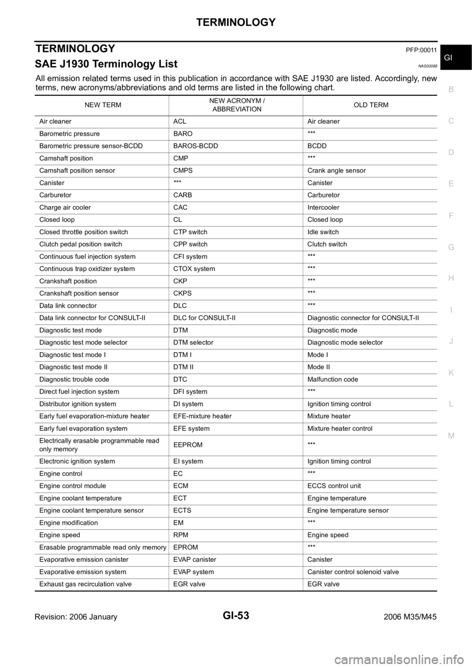
TERMINOLOGYPFP:00011
SAE J1930 Terminology List NAS00088
All emission related terms used in this publication in accordance with SAE J1930 are listed. Accordingly, new
terms, new acronyms/abbreviations and old terms are listed in the following chart.
NEW TERMNEW ACRONYM /
ABBREVIATIONOLD TERM
Air cleaner ACL Air cleaner
Barometric pressure BARO ***
Barometric pressure sensor-BCDD BAROS-BCDD BCDD
Camshaft position CMP ***
Camshaft position sensor CMPS Crank angle sensor
Canister *** Canister
Carburetor CARB Carburetor
Charge air cooler CAC Intercooler
Closed loop CL Closed loop
Closed throttle position switch CTP switch Idle switch
Clutch pedal position switch CPP switch Clutch switch
Continuous fuel injection system CFI system ***
Continuous trap oxidizer system CTOX system ***
Crankshaft position CKP ***
Crankshaft position sensor CKPS ***
Data link connector DLC ***
Data link connector for CONSULT-II DLC for CONSULT-II Diagnostic connector for CONSULT-II
Diagnostic test mode DTM Diagnostic mode
Diagnostic test mode selector DTM selector Diagnostic mode selector
Diagnostic test mode I DTM I Mode I
Diagnostic test mode II DTM II Mode II
Diagnostic trouble code DTC Malfunction code
Direct fuel injection system DFI system ***
Distributor ignition system DI system Ignition timing control
Early fuel evaporation-mixture heater EFE-mixture heater Mixture heater
Early fuel evaporation system EFE system Mixture heater control
Electrically erasable programmable read
only memoryEEPROM ***
Electronic ignition system EI system Ignition timing control
Engine control EC ***
Engine control module ECM ECCS control unit
Engine coolant temperature ECT Engine temperature
Engine coolant temperature sensor ECTS Engine temperature sensor
Engine modification EM ***
Engine speed RPM Engine speed
Erasable programmable read only memory EPROM ***
Evaporative emission canister EVAP canister Canister
Evaporative emission system EVAP system Canister control solenoid valve
Exhaust gas recirculation valve EGR valve EGR valve
Page 3643 of 5621
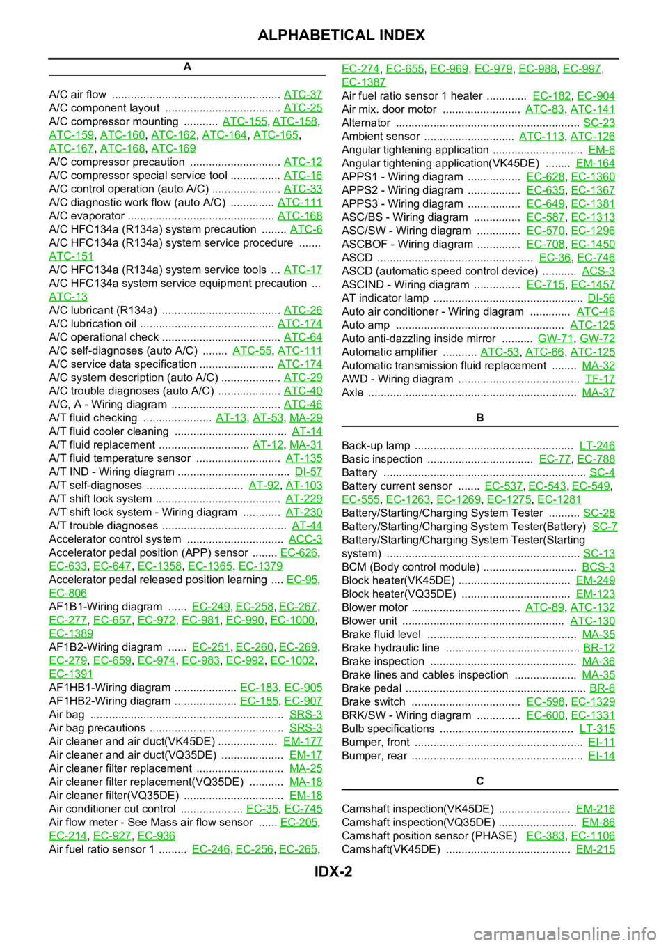
IDX-2
ALPHABETICAL INDEX
A
A/C air flow ...................................................... ATC-37
A/C component layout ..................................... ATC-25
A/C compressor mounting ........... ATC-155, ATC-158,
ATC-159
, ATC-160, ATC-162, ATC-164, ATC-165,
ATC-167
, ATC-168, ATC-169
A/C compressor precaution ............................. ATC-12
A/C compressor special service tool ................ ATC-16
A/C control operation (auto A/C) ...................... ATC-33
A/C diagnostic work flow (auto A/C) .............. ATC-111
A/C evaporator ............................................... ATC-168
A/C HFC134a (R134a) system precaution ........ ATC-6
A/C HFC134a (R134a) system service procedure .......
ATC-151
A/C HFC134a (R134a) system service tools ... ATC-17
A/C HFC134a system service equipment precaution ...
ATC-13
A/C lubricant (R134a) ...................................... ATC-26
A/C lubrication oil ........................................... ATC-174
A/C operational check ...................................... ATC-64
A/C self-diagnoses (auto A/C) ........ ATC-55, ATC-111
A/C service data specification ........................ ATC-174
A/C system description (auto A/C) ................... ATC-29
A/C trouble diagnoses (auto A/C) .................... ATC-40
A/C, A - Wiring diagram ................................... ATC-46
A/T fluid checking ...................... AT-13, AT-53, MA-29
A/T fluid cooler cleaning .................................... AT-14
A/T fluid replacement ............................. AT-12, MA-31
A/T fluid temperature sensor ........................... AT-135
A/T IND - Wiring diagram .................................... DI-57
A/T self-diagnoses ............................... AT-92, AT-103
A/T shift lock system ........................................ AT-229
A/T shift lock system - Wiring diagram ............ AT-230
A/T trouble diagnoses ........................................ AT-44
Accelerator control system ............................... ACC-3
Accelerator pedal position (APP) sensor ........ EC-626,
EC-633
, EC-647, EC-1358, EC-1365, EC-1379
Accelerator pedal released position learning .... EC-95,
EC-806
AF1B1-Wiring diagram ...... EC-249, EC-258, EC-267,
EC-277
, EC-657, EC-972, EC-981, EC-990, EC-1000,
EC-1389
AF1B2-Wiring diagram ...... EC-251, EC-260, EC-269,
EC-279
, EC-659, EC-974, EC-983, EC-992, EC-1002,
EC-1391
AF1HB1-Wiring diagram .................... EC-183, EC-905
AF1HB2-Wiring diagram .................... EC-185, EC-907
Air bag .............................................................. SRS-3
Air bag precautions ........................................... SRS-3
Air cleaner and air duct(VK45DE) ................... EM-177
Air cleaner and air duct(VQ35DE) .................... EM-17
Air cleaner filter replacement ............................ MA-25
Air cleaner filter replacement(VQ35DE) ........... MA-18
Air cleaner filter(VQ35DE) ................................ EM-18
Air conditioner cut control .................... EC-35, EC-745
Air flow meter - See Mass air flow sensor ...... EC-205,
EC-214
, EC-927, EC-936
Air fuel ratio sensor 1 ......... EC-246, EC-256, EC-265, EC-274
, EC-655, EC-969, EC-979, EC-988, EC-997,
EC-1387
Air fuel ratio sensor 1 heater ............. EC-182, EC-904
Air mix. door motor ......................... ATC-83, ATC-141
Alternator ........................................................... SC-23
Ambient sensor ............................. ATC-113, ATC-126
Angular tightening application ............................. EM-6
Angular tightening application(VK45DE) ........ EM-164
APPS1 - Wiring diagram ................. EC-628, EC-1360
APPS2 - Wiring diagram ................. EC-635, EC-1367
APPS3 - Wiring diagram ................. EC-649, EC-1381
ASC/BS - Wiring diagram ............... EC-587, EC-1313
ASC/SW - Wiring diagram .............. EC-570, EC-1296
ASCBOF - Wiring diagram .............. EC-708, EC-1450
ASCD .................................................. EC-36, EC-746
ASCD (automatic speed control device) ........... ACS-3
ASCIND - Wiring diagram ............... EC-715, EC-1457
AT indicator lamp ................................................ DI-56
Auto air conditioner - Wiring diagram ............. ATC-46
Auto amp ...................................................... ATC-125
Auto anti-dazzling inside mirror .......... GW-71, GW-72
Automatic amplifier ........... ATC-53, ATC-66, ATC-125
Automatic transmission fluid replacement ........ MA-32
AWD - Wiring diagram ....................................... TF-17
Axle ................................................................... MA-37
B
Back-up lamp ................................................... LT-246
Basic inspection .................................. EC-77, EC-788
Battery ................................................................. SC-4
Battery current sensor ....... EC-537, EC-543, EC-549,
EC-555
, EC-1263, EC-1269, EC-1275, EC-1281
Battery/Starting/Charging System Tester .......... SC-28
Battery/Starting/Charging System Tester(Battery) SC-7
Battery/Starting/Charging System Tester(Starting
system) .............................................................. SC-13
BCM (Body control module) .............................. BCS-3
Block heater(VK45DE) .................................... EM-249
Block heater(VQ35DE) ................................... EM-123
Blower motor ................................... ATC-89, ATC-132
Blower unit .................................................... ATC-130
Brake fluid level ................................................ MA-35
Brake hydraulic line ........................................... BR-12
Brake inspection ............................................... MA-36
Brake lines and cables inspection .................... MA-35
Brake pedal .......................................................... BR-6
Brake switch ................................... EC-598, EC-1329
BRK/SW - Wiring diagram .............. EC-600, EC-1331
Bulb specifications ........................................... LT-315
Bumper, front ...................................................... EI-11
Bumper, rear ....................................................... EI-14
C
Camshaft inspection(VK45DE) ....................... EM-216
Camshaft inspection(VQ35DE) ......................... EM-86
Camshaft position sensor (PHASE) EC-383, EC-1106
Camshaft(VK45DE) ........................................ EM-215
Page 3644 of 5621
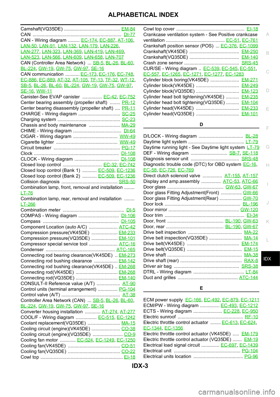
IDX-3
A
C
D
E
F
G
H
I
J
K
L B
IDX
ALPHABETICAL INDEX
Camshaft(VQ35DE) ........................................... EM-84
CAN .................................................................... DI-77
CAN - Wiring diagram ......... EC-174, EC-887, AT-106,
LAN-50
, LAN-91, LAN-132, LAN-179, LAN-226,
LAN-277
, LAN-323, LAN-369, LAN-419, LAN-469,
LAN-523
, LAN-566, LAN-609, LAN-658, LAN-707
CAN (Controller Area Network) ... SB-5, BL-26, BL-60,
BL-224
, GW-19, GW-75, GW-97, SE-16
CAN communication ........... EC-173, EC-176, EC-748,
EC-886
, EC-889, AT-32, AT-105, TF-13, TF-32, WT-12,
SB-5
, BL-26, BL-60, BL-224, GW-19, GW-75, GW-97,
SE-16
, WW-11
Canister-See EVAP canister ............... EC-42, EC-752
Center bearing assembly (propeller shaft) ........ PR-12
Center bearing disassembly (propeller shaft) .... PR-11
CHARGE - Wiring diagram ................................ SC-25
Charging system ................................................ SC-23
Chassis and body maintenance ........................ MA-29
CHIME - Wiring diagram ..................................... DI-64
CIGAR - Wiring diagram .................................. WW-49
Cigarette lighter ............................................... WW-49
Circuit breaker ................................................... PG-17
Clock ................................................................. DI-108
CLOCK - Wiring diagram .................................. DI-108
Closed loop control .............................. EC-32, EC-742
Closed loop control (Bank 1) ........... EC-509, EC-1236
Closed loop control (Bank 2) ........... EC-509, EC-1236
Collision diagnosis ........................................... SRS-50
Combination lamp, front, removal and installation ........
LT-76
Combination lamp, rear, removal and installation ........
LT-266
Combination meter ............................................... DI-5
COMPAS - Wiring diagram ............................... DI-106
Compass .......................................................... DI-105
Component Location (auto A/C) ...................... ATC-42
Compression pressure(VK45DE) .................... EM-233
Compression pressure(VQ35DE) .................... EM-101
Compressor special service tool ...................... ATC-16
Condenser ..................................................... ATC-165
Connecting rod bearing clearance(VK45DE) .. EM-273
Connecting rod bushing clearance .................. EM-142
Connecting rod bushing clearance(VK45DE) .. EM-268
Connecting rod(VK45DE) ................................ EM-268
Connecting rod(VQ35DE) ................................ EM-140
CONSULT-II Reference value (A/T) .................. AT-90
Control units (terminal arrangement) ............... PG-104
Control valve (A/T) ............................................. AT-38
Controller Area Network (CAN) ... SB-5, BL-26, BL-60,
BL-224
, GW-19, GW-75, GW-97, SE-16
Converter housing installation ............ AT-274, AT-277
COOL/F - Wiring diagram ................ EC-515, EC-1242
Coolant replacement(VQ35DE) ......................... MA-15
Cooling circuit (engine)(VK45DE) ...................... CO-38
Cooling circuit (engine)(VQ35DE) ....................... CO-9
Cooling fan motor ............ EC-524, EC-1249, EC-1250
Cooling fan(VK45DE) ........................................ CO-51
Cooling fan(VQ35DE) ........................................ CO-22
Cowl top ............................................................... EI-18
Cowl top cover .................................................... EI-18
Crankcase ventilation system - See Positive crankcase
ventilation ............................................. EC-51
, EC-761
Crankshaft position sensor (POS) ... EC-376, EC-1099
Crankshaft(VK45DE) ...................................... EM-250
Crankshaft(VQ35DE) ...................................... EM-140
Crash zone sensor .......................................... SRS-45
CUR/SE - Wiring diagram .. EC-539, EC-545, EC-551,
EC-557
, EC-1265, EC-1271, EC-1277, EC-1283
Cylinder block boring(VK45DE) ...................... EM-271
Cylinder block(VK45DE) ................................. EM-249
Cylinder block(VQ35DE) ................................. EM-123
Cylinder head bolt tightening(VK45DE) .......... EM-235
Cylinder head bolt tightening(VQ35DE) .......... EM-104
Cylinder head(VK45DE) ................................. EM-233
Cylinder head(VQ35DE) ................................. EM-101
D
D/LOCK - Wiring diagram .................................. BL-28
Daytime light system ........................................... LT-79
Daytime running light - See Daytime light system LT-79
DEF - Wiring diagram ............................ SB-7, SE-118
Diagnosis sensor unit ..................................... SRS-48
Diagnostic trouble code (DTC) for OBD system EC-16,
EC-58
, EC-726, EC-769
Direct clutch solenoid valve ............... AT-155, AT-157
Display and amp.assembly ............... ATC-53, ATC-66
Door glass ........................................... GW-63, GW-67
Door glass Fitting Adjustment(Front) ................ GW-66
Door glass Fitting Adjustment(Rear) ................. GW-70
Door lock .......................................................... BL-196
Door mirror ...................................................... GW-120
Door trim ............................................................. EI-34
Door, front ........................................... BL-190, GW-63
Door, rear ............................................ BL-190, GW-67
Drive belt inspection ......................................... MA-22
Drive belt inspection(VQ35DE) ......................... MA-14
Drive belt(VK45DE) ........................................ EM-174
Drive belt(VQ35DE) .......................................... EM-15
Drive shaft ......................................................... MA-38
Drive shaft (rear) ............................................... RAX-8
Driver air bag .................................................. SRS-38
DTRL - Wiring diagram ....................................... LT-84
Duct and grilles .............................................. ATC-144
E
ECM power supply EC-166
, EC-492, EC-879, EC-1211
ECM/PW - Wiring diagram ............... EC-493, EC-1212
ECTS - Wiring diagram ...................... EC-228, EC-950
Electric sunroof .................................................. RF-10
Electric throttle control actuator ........ EC-613, EC-624,
EC-1344
, EC-1356
Electric throttle control actuator (VK45DE) ..... EM-179
Electric throttle control actuator (VQ35DE) ....... EM-19
Electrical load signal circuit .............. EC-697, EC-1439
Electrical unit ................................................... PG-104
Electrical units location ...................................... PG-96
Page 3670 of 5621
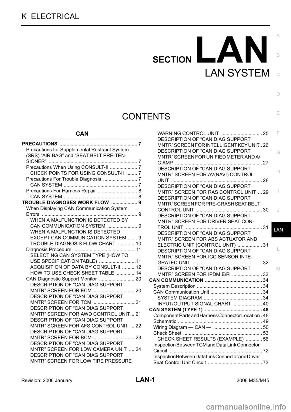
LAN-1
LAN SYSTEM
K ELECTRICAL
CONTENTS
C
D
E
F
G
H
I
J
L
M
SECTION LAN
A
B
LAN
Revision: 2006 January2006 M35/M45
LAN SYSTEM
CAN
PRECAUTIONS .......................................................... 7
Precautions for Supplemental Restraint System
(SRS) “AIR BAG” and “SEAT BELT PRE-TEN-
SIONER” .................................................................. 7
Precautions When Using CONSULT-II ..................... 7
CHECK POINTS FOR USING CONSULT-II ......... 7
Precautions For Trouble Diagnosis .......................... 7
CAN SYSTEM ....................................................... 7
Precautions For Harness Repair .............................. 8
CAN SYSTEM ....................................................... 8
TROUBLE DIAGNOSES WORK FLOW .................... 9
When Displaying CAN Communication System
Errors ....................................................................... 9
WHEN A MALFUNCTION IS DETECTED BY
CAN COMMUNICATION SYSTEM ....................... 9
WHEN A MALFUNCTION IS DETECTED
EXCEPT CAN COMMUNICATION SYSTEM ........ 9
TROUBLE DIAGNOSIS FLOW CHART ............. 10
Diagnosis Procedure ............................................... 11
SELECTING CAN SYSTEM TYPE (HOW TO
USE SPECIFICATION TABLE) ............................ 11
ACQUISITION OF DATA BY CONSULT-II .......... 12
HOW TO USE CHECK SHEET TABLE .............. 14
CAN Diagnostic Support Monitor ........................... 20
DESCRIPTION OF “CAN DIAG SUPPORT
MNTR” SCREEN FOR ECM ............................... 20
DESCRIPTION OF “CAN DIAG SUPPORT
MNTR” SCREEN FOR TCM ............................... 21
DESCRIPTION OF “CAN DIAG SUPPORT
MNTR” SCREEN FOR AWD CONTROL UNIT ... 21
DESCRIPTION OF “CAN DIAG SUPPORT
MNTR” SCREEN FOR AFS CONTROL UNIT .... 22
DESCRIPTION OF “CAN DIAG SUPPORT
MNTR” SCREEN FOR BCM ............................... 23
DESCRIPTION OF “CAN DIAG SUPPORT
MNTR” SCREEN FOR LDW CAMERA UNIT ..... 24
DESCRIPTION OF “CAN DIAG SUPPORT
MNTR” SCREEN FOR LOW TIRE PRESSURE WARNING CONTROL UNIT ............................... 25
DESCRIPTION OF “CAN DIAG SUPPORT
MNTR” SCREEN FOR INTELLIGENT KEY UNIT ... 26
DESCRIPTION OF “CAN DIAG SUPPORT
M N T R ” S C R E E N F O R U N I F I E D M E T E R A N D A /
C AMP. ................................................................. 27
DESCRIPTION OF “CAN DIAG SUPPORT
MNTR” SCREEN FOR AV(NAVI) CONTROL
UNIT .................................................................... 28
DESCRIPTION OF “CAN DIAG SUPPORT
MNTR” SCREEN FOR RAS CONTROL UNIT .... 29
DESCRIPTION OF “CAN DIAG SUPPORT
M N T R ” S C R E E N F O R P R E - C R A S H S E A T B E L T
CONTROL UNIT ................................................. 30
DESCRIPTION OF “CAN DIAG SUPPORT
MNTR” SCREEN FOR DRIVER SEAT CON-
TROL UNIT ...................................................... ... 31
DESCRIPTION OF “CAN DIAG SUPPORT
MNTR” SCREEN FOR ABS ACTUATOR AND
ELECTRIC UNIT (CONTROL UNIT) ................... 31
DESCRIPTION OF “CAN DIAG SUPPORT
MNTR” SCREEN FOR ICC SENSOR INTE-
GRATED UNIT .................................................... 32
DESCRIPTION OF “CAN DIAG SUPPORT
MNTR” SCREEN FOR IPDM E/R ....................... 33
CAN COMMUNICATION ........................................... 34
System Description ................................................. 34
CAN Communication Unit ....................................... 34
SYSTEM DIAGRAM ............................................ 34
INPUT/OUTPUT SIGNAL CHART ...................... 40
CAN SYSTEM (TYPE 1) ........................................... 48
Component Parts and Harness Connector Location ... 48
Schematic ............................................................... 49
Wiring Diagram — CAN — ..................................... 50
Check Sheet ........................................................... 53
CHECK SHEET RESULTS (EXAMPLE) ............. 56
Inspection Between TCM and Data Link Connector
Circuit ..................................................................
... 72
Inspection Between Data Link Connector and Driver
Seat Control Unit Circuit ......................................
... 73
Page 3672 of 5621
LAN-3
C
D
E
F
G
H
I
J
L
MA
B
LAN
Revision: 2006 January2006 M35/M45 Inspection Between Data Link Connector and Pre-
Crash Seat Belt Control Unit Circuit .....................256
Inspection Between Pre-Crash Seat Belt Control
Unit and Driver Seat Control Unit Circuit ..............257
Inspection Between Driver Seat Control Unit and
ABS Actuator and Electric Unit (Control Unit) Circuit .257
Inspection Between ABS Actuator and Electric Unit
and ICC Sensor Integrated Unit Circuit ................258
ECM Circuit Inspection .........................................259
TCM Circuit Inspection .........................................259
AFS Control Unit Circuit Inspection ......................260
BCM Circuit Inspection .........................................260
LDW Camera Unit Circuit Inspection ...................261
Low Tire Pressure Warning Control Unit Circuit
Inspection .............................................................261
Steering Angle Sensor Circuit Inspection .............262
Intelligent Key Unit Circuit Inspection ...................262
Unified Meter and A/C Amp. Circuit Inspection ....263
NAVI Control Unit Circuit Inspection .....................263
Data Link Connector Circuit Inspection ................264
Pre-Crash Seat Belt Control Unit Circuit Inspection .264
Driver Seat Control Unit Circuit Inspection ...........265
ABS Actuator and Electric Unit (Control Unit) Circuit
Inspection .............................................................265
ICC Sensor Integrated Unit Circuit Inspection .....266
IPDM E/R Circuit Inspection .................................266
CAN Communication Circuit Inspection ...............267
IPDM E/R Ignition Relay Circuit Inspection ..........274
CAN SYSTEM (TYPE 6) .........................................275
Component Parts and Harness Connector Location .275
Schematic ............................................................276
Wiring Diagram — CAN — ...................................277
Check Sheet .........................................................281
CHECK SHEET RESULTS (EXAMPLE) ...........284
Inspection Between TCM and Data Link Connector
Circuit ...................................................................303
Inspection Between Data Link Connector and RAS
Control Unit Circuit ...............................................304
Inspection Between RAS Control Unit and Driver
Seat Control Unit Circuit ......................................
.305
Inspection Between Driver Seat Control Unit and
ABS Actuator and Electric Unit (Control Unit) Circuit .305
ECM Circuit Inspection .........................................306
TCM Circuit Inspection .........................................306
AFS Control Unit Circuit Inspection ......................307
BCM Circuit Inspection .........................................307
Low Tire Pressure Warning Control Unit Circuit
Inspection .............................................................308
Steering Angle Sensor Circuit Inspection .............308
Intelligent Key Unit Circuit Inspection ...................309
Unified Meter and A/C Amp. Circuit Inspection ....309
AV Control Unit Circuit Inspection ........................310
Data Link Connector Circuit Inspection ................310
RAS Control Unit Circuit Inspection ...................... 311
Driver Seat Control Unit Circuit Inspection ............ 311
ABS Actuator and Electric Unit (Control Unit) Circuit
Inspection ............................................................
.312
IPDM E/R Circuit Inspection .................................312CAN Communication Circuit Inspection ...............313
IPDM E/R Ignition Relay Circuit Inspection ..........320
CAN SYSTEM (TYPE 7) .........................................321
Component Parts and Harness Connector Location .321
Schematic .............................................................322
Wiring Diagram — CAN — ...................................323
Check Sheet .........................................................327
CHECK SHEET RESULTS (EXAMPLE) ...........330
Inspection Between TCM and Data Link Connector
Circuit ...................................................................349
Inspection Between Data Link Connector and RAS
Control Unit Circuit ...............................................350
Inspection Between RAS Control Unit and Driver
Seat Control Unit Circuit ......................................
.351
Inspection Between Driver Seat Control Unit and
ABS Actuator and Electric Unit (Control Unit) Circuit .351
ECM Circuit Inspection .........................................352
TCM Circuit Inspection .........................................352
AFS Control Unit Circuit Inspection ......................353
BCM Circuit Inspection .........................................353
Low Tire Pressure Warning Control Unit Circuit
Inspection .............................................................354
Steering Angle Sensor Circuit Inspection .............354
Intelligent Key Unit Circuit Inspection ...................355
Unified Meter and A/C Amp. Circuit Inspection ....355
NAVI Control Unit Circuit Inspection .....................356
Data Link Connector Circuit Inspection ................356
RAS Control Unit Circuit Inspection ......................357
Driver Seat Control Unit Circuit Inspection ...........357
ABS Actuator and Electric Unit (Control Unit) Circuit
Inspection .............................................................358
IPDM E/R Circuit Inspection .................................358
CAN Communication Circuit Inspection ...............359
IPDM E/R Ignition Relay Circuit Inspection ..........366
CAN SYSTEM (TYPE 8) .........................................367
Component Parts and Harness Connector Location .367
Schematic .............................................................368
Wiring Diagram — CAN — ...................................369
Check Sheet .........................................................373
CHECK SHEET RESULTS (EXAMPLE) ...........376
Inspection Between TCM and Data Link Connector
Circuit ...................................................................397
Inspection Between Data Link Connector and RAS
Control Unit Circuit ...............................................398
Inspection Between RAS Control Unit and Pre-
Crash Seat Belt Control Unit Circuit .....................399
Inspection Between Pre-Crash Seat Belt Control
Unit and Driver Seat Control Unit Circuit ..............399
Inspection Between Driver Seat Control Unit and
ABS Actuator and Electric Unit (Control Unit) Circuit .400
ECM Circuit Inspection .........................................400
TCM Circuit Inspection .........................................401
AFS Control Unit Circuit Inspection ......................402
BCM Circuit Inspection .........................................402
Low Tire Pressure Warning Control Unit Circuit
Inspection ............................................................
.403
Steering Angle Sensor Circuit Inspection .............403
Intelligent Key Unit Circuit Inspection ...................404
Unified Meter and A/C Amp. Circuit Inspection ....404