2006 INFINITI M35 low oil pressure
[x] Cancel search: low oil pressurePage 3339 of 5621
![INFINITI M35 2006 Factory Service Manual EM-276
[VK45DE]
SERVICE DATA AND SPECIFICATIONS (SDS)
Revision: 2006 January2006 M35/M45
SERVICE DATA AND SPECIFICATIONS (SDS)PFP:00030
Standard and LimitNBS004PQ
GENERAL SPECIFICATIONS
DRIVE BELTS
IN INFINITI M35 2006 Factory Service Manual EM-276
[VK45DE]
SERVICE DATA AND SPECIFICATIONS (SDS)
Revision: 2006 January2006 M35/M45
SERVICE DATA AND SPECIFICATIONS (SDS)PFP:00030
Standard and LimitNBS004PQ
GENERAL SPECIFICATIONS
DRIVE BELTS
IN](/manual-img/42/57023/w960_57023-3338.png)
EM-276
[VK45DE]
SERVICE DATA AND SPECIFICATIONS (SDS)
Revision: 2006 January2006 M35/M45
SERVICE DATA AND SPECIFICATIONS (SDS)PFP:00030
Standard and LimitNBS004PQ
GENERAL SPECIFICATIONS
DRIVE BELTS
INTAKE MANIFOLD AND EXHAUST MANIFOLD
Unit: mm (in) Cylinder arrangementV-8
Displacement cm
3 (cu in)4,494 (274.22)
Bore and stroke mm (in)93 x 82.7 (3.66 x 3.256)
Valve arrangementDOHC
Firing order1-8-7-3-6-5-4-2
Number of piston ringsCompression 2
Oil 1
Number of main bearings5
Compression ratio10.5
Compression pressure
kPa (kg/cm
2 , psi)/300 rpmStandard 1,320 (13.5, 191)
Minimum 1,130 (11.5, 164)
Differential limit
between cylinders98 (1.0, 14)
Cylinder number
Va l v e t i m i n g
Unit: degree
abcde f
228 240 -2 62 4 44
SEM957C
PBIC0187E
Tension of drive belts Auto adjustment by auto tensioner
Items Limit
Surface distortionIntake manifold (upper) 0.1 (0.004)
Intake manifold (lower) 0.1 (0.004)
Exhaust manifold 0.3 (0.012)
Page 3433 of 5621
![INFINITI M35 2006 Factory Service Manual FSU-6
[2WD]
FRONT SUSPENSION ASSEMBLY
Revision: 2006 January2006 M35/M45
FRONT SUSPENSION ASSEMBLYPFP:54010
On-Vehicle Inspection and ServiceNES000IA
Make sure the mounting conditions (looseness, INFINITI M35 2006 Factory Service Manual FSU-6
[2WD]
FRONT SUSPENSION ASSEMBLY
Revision: 2006 January2006 M35/M45
FRONT SUSPENSION ASSEMBLYPFP:54010
On-Vehicle Inspection and ServiceNES000IA
Make sure the mounting conditions (looseness,](/manual-img/42/57023/w960_57023-3432.png)
FSU-6
[2WD]
FRONT SUSPENSION ASSEMBLY
Revision: 2006 January2006 M35/M45
FRONT SUSPENSION ASSEMBLYPFP:54010
On-Vehicle Inspection and ServiceNES000IA
Make sure the mounting conditions (looseness, back lash) of each component and component conditions
(wear, damage) are normal.
INSPECTION OF LOWER BALL JOINT END PLAY
1. Set front wheels in a straight-ahead position. Do not depress brake pedal.
2. Place an iron bar or similar tool between transverse link and steering knuckle.
3. Measure axial end play by prying it up and down.
CAUTION:
Be careful not to damage ball joint boot. Do not damage the installation position by applying
excessive force.
SHOCK ABSORBER INSPECTION
Check for oil leakage, damage and breakage of installation positions.
Wheel Alignment InspectionNES000IB
DESCRIPTION
Measure wheel alignment under unladen conditions.
NOTE:
“Unladen conditions” means that fuel, engine coolant, and lubricant are full. Spare tire, jack, hand tools and
mats are in designated positions.
PRELIMINARY CHECK
Check the following:
1. Tires for improper air pressure and wear.
2. Road wheels for runout. Refer to WT-6, "
ROAD WHEEL" .
3. Wheel bearing axial end play. Refer to FAX-5, "
WHEEL BEARING INSPECTION" .
4. Transverse link ball joint axial end play. Refer to FSU-14, "
INSPECTION AFTER REMOVAL" .
5. Shock absorber operation.
6. Each mounting part of axle and suspension for looseness and deformation.
7. Each of suspension member, shock absorber, upper link and transverse link for cracks, deformation and
other damage.
8. Vehicle height (posture).
GENERAL INFORMATION AND RECOMMENDATIONS
A four-wheel thrust alignment should be performed.
–This type of alignment is recommended for any NISSAN/INFINITI vehicle.
–The four-wheel “thrust” process helps ensure that the vehicle is properly aligned and the steering wheel is
centered.
–The alignment rack itself should be capable of accepting any NISSAN/INFINITI vehicle.
–The rack should be checked to ensure that it is level.
Make sure the machine is properly calibrated.
–Your alignment equipment should be regularly calibrated in order to give correct information.
–Check with the manufacturer of your specific equipment for their recommended Service/Calibration
Schedule.Axial end play : 0 mm (0 in)
Page 3450 of 5621
![INFINITI M35 2006 Factory Service Manual FRONT SUSPENSION ASSEMBLY
FSU-23
[AWD]
C
D
F
G
H
I
J
K
L
MA
B
FSU
Revision: 2006 January2006 M35/M45
FRONT SUSPENSION ASSEMBLYPFP:54010
On-Vehicle Inspection and ServiceNES000IQ
Make sure the mount INFINITI M35 2006 Factory Service Manual FRONT SUSPENSION ASSEMBLY
FSU-23
[AWD]
C
D
F
G
H
I
J
K
L
MA
B
FSU
Revision: 2006 January2006 M35/M45
FRONT SUSPENSION ASSEMBLYPFP:54010
On-Vehicle Inspection and ServiceNES000IQ
Make sure the mount](/manual-img/42/57023/w960_57023-3449.png)
FRONT SUSPENSION ASSEMBLY
FSU-23
[AWD]
C
D
F
G
H
I
J
K
L
MA
B
FSU
Revision: 2006 January2006 M35/M45
FRONT SUSPENSION ASSEMBLYPFP:54010
On-Vehicle Inspection and ServiceNES000IQ
Make sure the mounting conditions (looseness, back lash) of each component and component conditions
(wear, damage) are normal.
INSPECTION OF LOWER BALL JOINT END PLAY
1. Set front wheels in a straight-ahead position. Do not depress brake pedal.
2. Place an iron bar or similar tool between transverse link and steering knuckle.
3. Measure axial end play by prying it up and down.
CAUTION:
Be careful not to damage ball joint boot. Do not damage the installation position by applying
excessive force.
SHOCK ABSORBER INSPECTION
Check for oil leakage, damage and breakage of installation positions.
Wheel Alignment InspectionNES000IR
DESCRIPTION
Measure wheel alignment under unladen conditions.
NOTE:
“Unladen conditions” means that fuel, engine coolant, and lubricant are full. Spare tire, jack, hand tools and
mats are in designated positions.
PRELIMINARY CHECK
Check the following:
1. Tires for improper air pressure and wear.
2. Road wheels for runout. Refer to WT-6, "
ROAD WHEEL" .
3. Wheel bearing axial end play. Refer to FAX-5, "
WHEEL BEARING INSPECTION" .
4. Transverse link ball joint axial end play. Refer to FSU-31, "
INSPECTION AFTER REMOVAL" .
5. Shock absorber operation.
6. Each mounting part of axle and suspension for looseness and deformation.
7. Each of suspension member, shock absorber, upper link and transverse link for cracks, deformation and
other damage.
8. Vehicle height (posture).
GENERAL INFORMATION AND RECOMMENDATIONS
A four-wheel thrust alignment should be performed.
–This type of alignment is recommended for any NISSAN/INFINITI vehicle.
–The four-wheel “thrust” process helps ensure that the vehicle is properly aligned and the steering wheel is
centered.
–The alignment rack itself should be capable of accepting any NISSAN/INFINITI vehicle.
–The rack should be checked to ensure that it is level.
Make sure the machine is properly calibrated.
–Your alignment equipment should be regularly calibrated in order to give correct information.
–Check with the manufacturer of your specific equipment for their recommended Service/Calibration
Schedule.Axial end play : 0 mm (0 in)
Page 3645 of 5621

IDX-4
ALPHABETICAL INDEX
Electronic ignition (EI) system ............. EC-33, EC-743
Engine control module (ECM) .......... EC-496, EC-1215
Engine control system diagram ........... EC-30, EC-740
Engine coolant temperature sensor (ECTS) ... EC-226,
EC-238
, EC-948, EC-961
Engine coolant(VK45DE) .................................. CO-40
Engine coolant(VQ35DE) ................................. CO-11
Engine oil filter replacement ............................. MA-26
Engine oil filter replacement(VQ35DE) ............. MA-19
Engine oil precautions .......................................... GI-8
Engine oil replacement(VQ35DE) ..................... MA-18
Engine oil(VK45DE) ........................................... LU-26
Engine oil(VQ35DE) ............................................ LU-7
Engine removal(VK45DE) ............................... EM-244
Engine removal(VQ35DE) .............................. EM-113
Engine room cover ............................................ EM-14
Engine room cover(VK45DE) ......................... EM-173
ETC1 - Wiring diagram .................... EC-614, EC-1345
ETC2 - Wiring diagram .................... EC-609, EC-1340
ETC3 - Wiring diagram .................... EC-620, EC-1352
EVAP canister ...................................... EC-42, EC-752
EVAP canister purge volume control solenoid valve ....
EC-412
, EC-420, EC-1132, EC-1140
EVAP canister vent control valve ...... EC-427, EC-434,
EC-1147
, EC-1154
EVAP control system (small leak) diagnosis .. EC-403,
EC-466
, EC-1124, EC-1185
EVAP control system pressure sensor ........... EC-440,
EC-443
, EC-450, EC-1160, EC-1163, EC-1170
EVAP control system purge flow monitoring diagnosis
EC-398
, EC-1119
EVAP vapor lines inspection ................. MA-21, MA-28
Evaporative emission (EVAP) system . EC-39, EC-749
Evaporator ..................................................... ATC-168
Exhaust manifold(VK45DE) ............................ EM-183
Exhaust system ................................................... EX-3
Exhaust system inspection ..................... EX-3, MA-29
Expansion valve ............................................. ATC-169
F
F/FOG - Wiring diagram ................................... LT-197
F/PUMP - Wiring diagram ................ EC-686, EC-1428
Final drive pre-inspection .................. FFD-16, RFD-19
Final drive removal and installation .. FFD-13, RFD-16
Floor trim ............................................................. EI-50
Flow charts ......................................................... GI-28
Fluid temperature sensor (A/T) ........................ AT-135
Fluorescent leak detector .............................. ATC-170
FPCM - Wiring diagram ................... EC-527, EC-1253
Freeze frame data ............................... EC-59, EC-770
Front brake solenoid valve ................. AT-151, AT-153
Front bumper ...................................................... EI-11
Front combination lamp removal and installation LT-76
Front door ............................. BL-190, BL-196, GW-63
Front passenger air bag .................................. SRS-42
Front seat belt .................................................... SB-30
Front seat belt pre-tensioner ..... SB-2, SRS-3, SRS-47
Front washer ...................................................... WW-4
Front wiper ......................................................... WW-4
FTS - Wiring diagram ....................................... AT-136
FTTS - Wiring diagram .... EC-345, EC-350, EC-1068,
EC-1073
Fuel cut control (at no load high engine speed) EC-34,
EC-744
Fuel filter replacement ......................................... FL-4
Fuel gauge ............................................................ DI-5
Fuel injection system (Bank 1) ......... EC-321, EC-332,
EC-1044
, EC-1055
Fuel injection system (Bank 2) ......... EC-321, EC-332,
EC-1044
, EC-1055
Fuel injector ................................................... EC-1420
Fuel injector and fuel tube(VK45DE) .............. EM-193
Fuel injector and fuel tube(VQ35DE) ................ EM-45
Fuel level sensor EC-475, EC-477, EC-479, EC-1194,
EC-1196
, EC-1198
Fuel line inspection .................................. FL-3, MA-25
Fuel line inspection(VQ35DE) .......................... MA-18
Fuel precautions ................................................... GI-6
Fuel pressure check ........................... EC-98, EC-809
Fuel pressure release ......................... EC-98, EC-809
Fuel pump ....................................... EC-685, EC-1427
Fuel pump and gauge .......................................... FL-4
Fuel pump control module .............. EC-525, EC-1251
Fuel pump dropping resistor ........... EC-525, EC-1251
Fuel system ......................................................... FL-3
Fuel tank ............................................................ FL-10
Fuel tank temperature sensor .......... EC-343, EC-349,
EC-1066
, EC-1072
Fuel tank vacuum relief valve ............. EC-42, EC-752
FUELB1 - Wiring diagram EC-323, EC-334, EC-1046,
EC-1057
FUELB2 - Wiring diagram EC-325, EC-336, EC-1048,
EC-1059
Fuse .................................................................. PG-17
Fuse and fusible link box ................................ PG-112
Fusible link ........................................................ PG-17
G
Gauges ................................................................. DI-5
Generator ........................................................... SC-23
Generator - See Alternator ................................ SC-23
Glass ........................ GW-11, GW-61, GW-63, GW-67
Grille - See Exterior ............................................ EI-16
Ground distribution ........................................... PG-46
H
H/LAMP - Wiring diagram ....................... LT-13
, LT-48
Harness connector .......................................... PG-102
Harness layout .................................................. PG-63
Hazard warning lamp ....................................... LT-211
Headlamp removal and installation .................... LT-76
Headlining - See Roof trim .................................. EI-52
Heated oxygen sensor 2 (bank 1) .... EC-286, EC-297,
EC-310
, EC-1009, EC-1020, EC-1033
Heated oxygen sensor 2 (bank 2) .... EC-286, EC-297,
Page 3646 of 5621

IDX-5
A
C
D
E
F
G
H
I
J
K
L B
IDX
ALPHABETICAL INDEX
EC-310, EC-1009, EC-1020, EC-1033
Heated oxygen sensor 2 heater (bank 1) ....... EC-189,
EC-911
Heated oxygen sensor 2 heater (bank 2) ....... EC-189,
EC-911
Heated seat ..................................................... SE-143
Heater and cooling unit (Heater core) ........... ATC-135
HFC134a (R134a) system precaution ............... ATC-6
HFC134a (R134a) system service procedure ATC-151
HFC134a (R134a) system service tools .......... ATC-17
HFC134a system service equipment precaution ..........
ATC-13
High and low reverse clutch solenoid valve .... AT-159,
AT-161
Hood ................................................................... BL-15
Horn ................................................................. WW-53
HORN - Wiring diagram ................................... WW-53
How to erase DTC for OBD system ..... EC-67, EC-778
HSEAT - Wiring diagram ................................. SE-146
I
IATS - Wiring diagram ....................... EC-223
, EC-945
ICC - Wiring diagram ....................................... ACS-21
ICC/BS - Wiring diagram ................. EC-578, EC-1304
ICC/SW - Wiring diagram ................ EC-563, EC-1289
ICCBOF - Wiring diagram ................ EC-700, EC-1442
Idle air volume learning ....................... EC-96, EC-807
Idle mixture ratio .................................. EC-84, EC-795
Idle speed .............................. EC-77, EC-788, EC-793
Idle speed control (ISC) .... EC-483, EC-485, EC-1202,
EC-1204
Ignition coil ....................................... EC-666, EC-1407
Ignition coil(VK45DE) ...................................... EM-190
Ignition coil(VQ35DE) ........................................ EM-42
Ignition control system ..................... EC-666, EC-1407
Ignition timing ........................ EC-77, EC-788, EC-793
IGNSYS - Wiring diagram ................ EC-667, EC-1408
Illumination ....................................................... LT-295
Illumination control ................. LT-291, LT-292, LT-293
In vehicle sensor ........................... ATC-116, ATC-127
INJECT - Wiring diagram ................. EC-680, EC-1421
Injector ............................................................. EC-679
Input clutch solenoid valve ................. AT-147, AT-149
Instrument panel .................................................. IP-10
Intake air temperature sensor ........... EC-221, EC-241,
EC-943
, EC-964
Intake door control linkage adjustment ............ ATC-88
Intake door motor ........................... ATC-86, ATC-133
Intake manifold collector(VQ35DE) ................... EM-19
Intake manifold(VK45DE) ................................ EM-179
Intake manifold(VQ35DE) .................................. EM-24
Intake sensor ................................ ATC-122, ATC-129
Intake valve timing control (Bank 1) .. EC-178, EC-891
Intake valve timing control (Bank 2) .. EC-178, EC-891
Intake valve timing control position sensor (Bank 1) ....
EC-1228
Intake valve timing control position sensor (Bank 2) ....
EC-1228
Intake valve timing control solenoid valve (Bank 1) ......
EC-197
, EC-920
Intake valve timing control solenoid valve (Bank 2) ......
EC-197
, EC-920
Integrated homelink transmitter ....................... BL-281
Intelligent cruise control (ICC) system .............. ACS-6
Interior ................................................................. EI-37
Interior lamp ...................................................... LT-267
IPDM (Intelligent power distribution module engine
room) ................................................................. PG-18
IVCB1 - Wiring diagram ..................... EC-198, EC-921
IVCB2 - Wiring diagram ..................... EC-200, EC-923
IVCSB1 - Wiring diagram ............................... EC-1229
IVCSB2 - Wiring diagram ............................... EC-1231
IVIS (Infiniti vehicle immobilizer system) precautions ...
GI-3
IVTB1 - Wiring diagram ................................... EC-894
IVTB2 - Wiring diagram ................................... EC-896
K
Knock sensor (KS) ........................... EC-371
, EC-1094
KS - Wiring diagram ......................... EC-372, EC-1095
L
LAN system circuit ........................................... ATC-70
Lane Departure Warning System ....................... DI-78
Laser beam aiming adjustment ....................... ACS-13
Latch (lower anchors and tether for children) system ...
SB-36
LDW .................................................................... DI-78
LDW - Wiring Diagram ........................................ DI-89
License lamp ..................................................... LT-249
Line pressure solenoid valve ........................... AT-130
Line pressure test (A/T) ..................................... AT-55
Liquid gasket application ......................... EM-7, LU-22
Liquid gasket application(VQ35DE) ........... LU-3, CO-3
Location of electrical units ................................. PG-96
Low coast brake solenoid valve ......... AT-163, AT-165
Low tire pressure warning system ...................... WT-9
Lubricant (R134a) A/C ..................................... ATC-26
Lubrication circuit (engine)(VK45DE) ................ LU-24
Lubrication circuit (engine)(VQ35DE) .................. LU-5
Lubrication oil A/C .......................................... ATC-174
M
MAFS - Wiring diagram ..... EC-208
, EC-216, EC-930,
EC-938
Magnet clutch .................................................. ATC-94
MAIN - Wiring diagram ........ EC-166, EC-879, AT-180
Maintenance (engine)(VQ35DE) ...................... MA-14
Major overhaul (Final drive) .............. FFD-15, RFD-18
Major overhaul (Transfer) .................................. TF-45
Malfunction indicator lamp (MIL) .......... EC-69, EC-780
Manual mode switch ........................................ AT-167
Mass air flow sensor (MAFS) ............ EC-205, EC-214,
EC-927
, EC-936
Page 3712 of 5621
![INFINITI M35 2006 Factory Service Manual CAN COMMUNICATION
LAN-43
[CAN]
C
D
E
F
G
H
I
J
L
MA
B
LAN
Revision: 2006 January2006 M35/M45
*1:with AFS model only
*2:with LDW model only
*3:with RAS model only
*4:with pre-crash seat belt model only INFINITI M35 2006 Factory Service Manual CAN COMMUNICATION
LAN-43
[CAN]
C
D
E
F
G
H
I
J
L
MA
B
LAN
Revision: 2006 January2006 M35/M45
*1:with AFS model only
*2:with LDW model only
*3:with RAS model only
*4:with pre-crash seat belt model only](/manual-img/42/57023/w960_57023-3711.png)
CAN COMMUNICATION
LAN-43
[CAN]
C
D
E
F
G
H
I
J
L
MA
B
LAN
Revision: 2006 January2006 M35/M45
*1:with AFS model only
*2:with LDW model only
*3:with RAS model only
*4:with pre-crash seat belt model only
*5:with ICC model only Deceleration degree commandment value signalRT
ICC OD cancel request signal R T
ICC operation signal R T
ICC warning lamp signalRT
Front wiper stop position signal R T
High beam status signal RT
Hood switch signal R T
Low beam status signal R R T
Oil pressure switch signalRT
TR
Rear window defogger control signal R R T
Starter relay status signal R TSignals
ECM
TCM
AFS control unit*1
BCM
LDW camera unit*2
Low tire pressure warning control unit
Steering angle sensor
Intelligent Key unit
Unified meter and A/C amp.
AV (NAVI) control unit
RAS control unit*3
Pre-crash seat belt control unit*4
Driver seat control unit
ABS actuator and electric unit (control unit)
ICC sensor integrated unit*5
IPDM E/R
Page 3716 of 5621
![INFINITI M35 2006 Factory Service Manual CAN COMMUNICATION
LAN-47
[CAN]
C
D
E
F
G
H
I
J
L
MA
B
LAN
Revision: 2006 January2006 M35/M45
*1:with AFS model only
*2:with LDW model only
*3:with pre-crash seat belt model only
*4:with ICC model only INFINITI M35 2006 Factory Service Manual CAN COMMUNICATION
LAN-47
[CAN]
C
D
E
F
G
H
I
J
L
MA
B
LAN
Revision: 2006 January2006 M35/M45
*1:with AFS model only
*2:with LDW model only
*3:with pre-crash seat belt model only
*4:with ICC model only](/manual-img/42/57023/w960_57023-3715.png)
CAN COMMUNICATION
LAN-47
[CAN]
C
D
E
F
G
H
I
J
L
MA
B
LAN
Revision: 2006 January2006 M35/M45
*1:with AFS model only
*2:with LDW model only
*3:with pre-crash seat belt model only
*4:with ICC model only Vehicle speed signalRRRRR TR
RR RR R TRRR R
Deceleration degree commandment value signalRT
ICC OD cancel request signal R T
ICC operation signal R T
ICC warning lamp signalRT
Front wiper stop position signal R T
High beam status signal RT
Hood switch signal R T
Low beam status signal R R T
Oil pressure switch signalRT
TR
Rear window defogger control signal R R T
Starter relay status signal R TSignals
ECM
TCM
AWD control unit
AFS control unit*1
BCM
LDW camera unit*2
Low tire pressure warning control unit
Steering angle sensor
Intelligent Key unit
Unified meter and A/C amp.
AV (NAVI) control unit
Pre-crash seat belt control unit*3
Driver seat control unit
ABS actuator and electric unit (control unit)
ICC sensor integrated unit*4
IPDM E/R
Page 4465 of 5621

LT-38
HEADLAMP (FOR USA) - CONVENTIONAL TYPE -
Revision: 2006 January2006 M35/M45
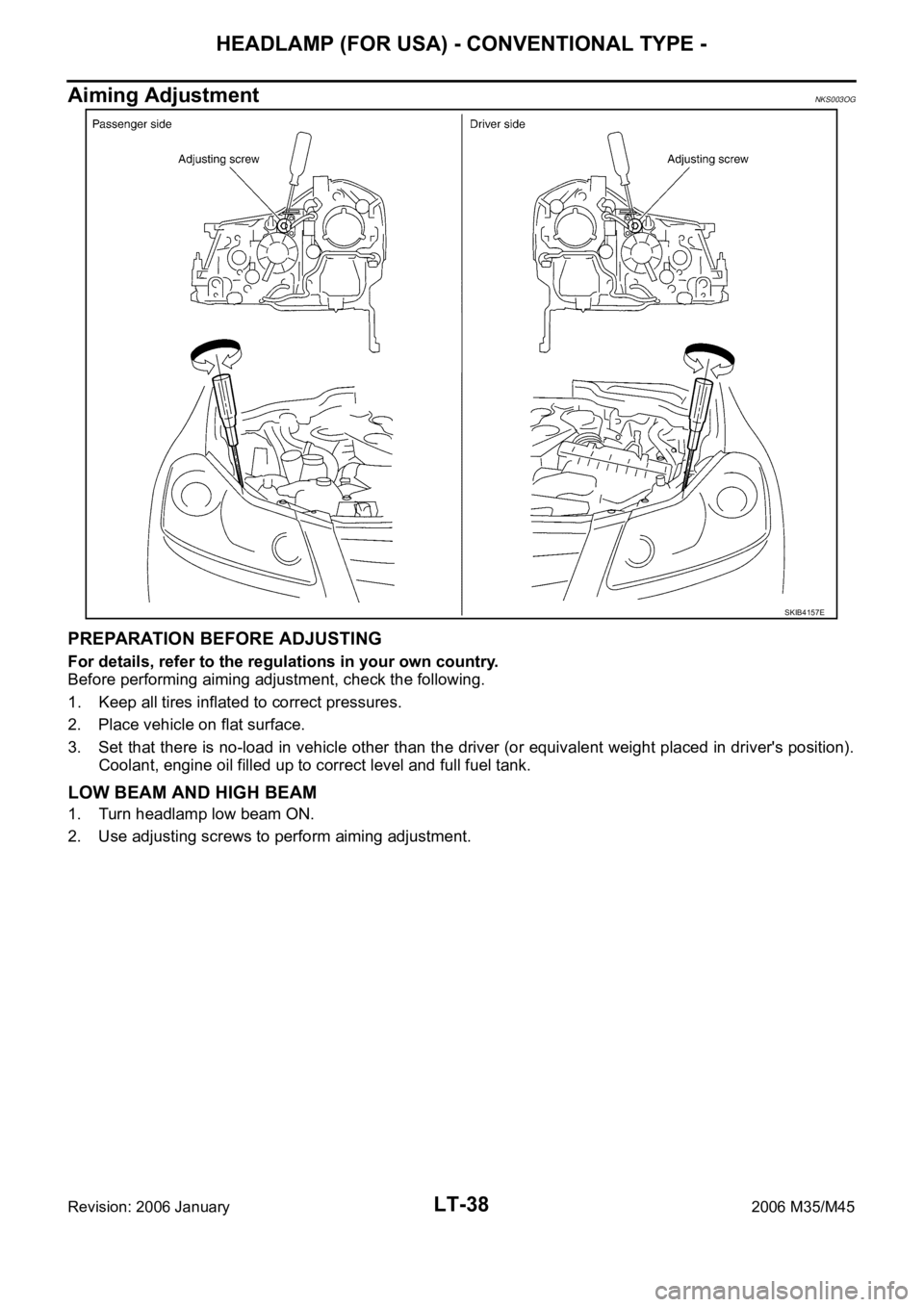
Aiming AdjustmentNKS003OG
PREPARATION BEFORE ADJUSTING
For details, refer to the regulations in your own country.
Before performing aiming adjustment, check the following.
1. Keep all tires inflated to correct pressures.
2. Place vehicle on flat surface.
3. Set that there is no-load in vehicle other than the driver (or equivalent weight placed in driver's position).
Coolant, engine oil filled up to correct level and full fuel tank.
LOW BEAM AND HIGH BEAM
1. Turn headlamp low beam ON.
2. Use adjusting screws to perform aiming adjustment.
SKIB4157E