Page 1270 of 5621
BODY REPAIR
BL-331
C
D
E
F
G
H
J
K
L
MA
B
BL
Revision: 2006 January2006 M35/M45
SIIA2491E
Page 1271 of 5621
BL-332
BODY REPAIR
Revision: 2006 January2006 M35/M45
REAR PANEL
Change parts
Rear panel assembly
SIIA2493E
Page 1272 of 5621
BODY REPAIR
BL-333
C
D
E
F
G
H
J
K
L
MA
B
BL
Revision: 2006 January2006 M35/M45
REAR FLOOR REAR
Work after rear panel has been removed.
SIIA2494E
Page 1273 of 5621
BL-334
BODY REPAIR
Revision: 2006 January2006 M35/M45
Change parts
Rear floor rearDifferential mounting bracket assembly
Page 1274 of 5621
BODY REPAIR
BL-335
C
D
E
F
G
H
J
K
L
MA
B
BL
Revision: 2006 January2006 M35/M45
REAR SIDE MEMBER EXTENSION
Work after rear panel has been removed.
SIIA2495E
Page 1275 of 5621
BL-336
BODY REPAIR
Revision: 2006 January2006 M35/M45
Change parts
Rear side member extension (LH)
Page 1290 of 5621

BRAKE MASTER CYLINDER
BR-15
C
D
E
G
H
I
J
K
L
MA
B
BR
Revision: 2006 January2006 M35/M45
BRAKE MASTER CYLINDERPFP:46010
On-Board InspectionNFS000P2
LEAK INSPECTION
Check for leaking in a master cylinder installation surface, a reservoir tank installation surface, and brake
tube connections.
Removal and InstallationNFS000P3
CAUTION:
Be careful not to splash brake fluid on painted areas; it may cause paint damage. If brake fluid is
splashed on painted areas, wash it away with water immediately.
Never scratch the piston of master cylinder when installing/removing because the piston is
exposed. Check if any dust is not on the piston, and wash with brake fluid if needed.
Hold cylinder body when handing master cylinder. Never hold the piston because the piston might
be detached if pulled strongly.
REMOVAL
1. Drain brake fluid. Refer to BR-10, "Drain and Refill" .
2. Disconnect brake fluid level switch harness connector.
3. Disconnect master cylinder brake tubes, using a flare nut wrench.
4. Remove master cylinder mounting nuts and remove master cylinder assembly from vehicle.
INSTALLATION
CAUTION:
Refill with new brake fluid “DOT 3”.
Never reuse drained brake fluid.
1. Installation is in the reverse order of removal.
CAUTION:
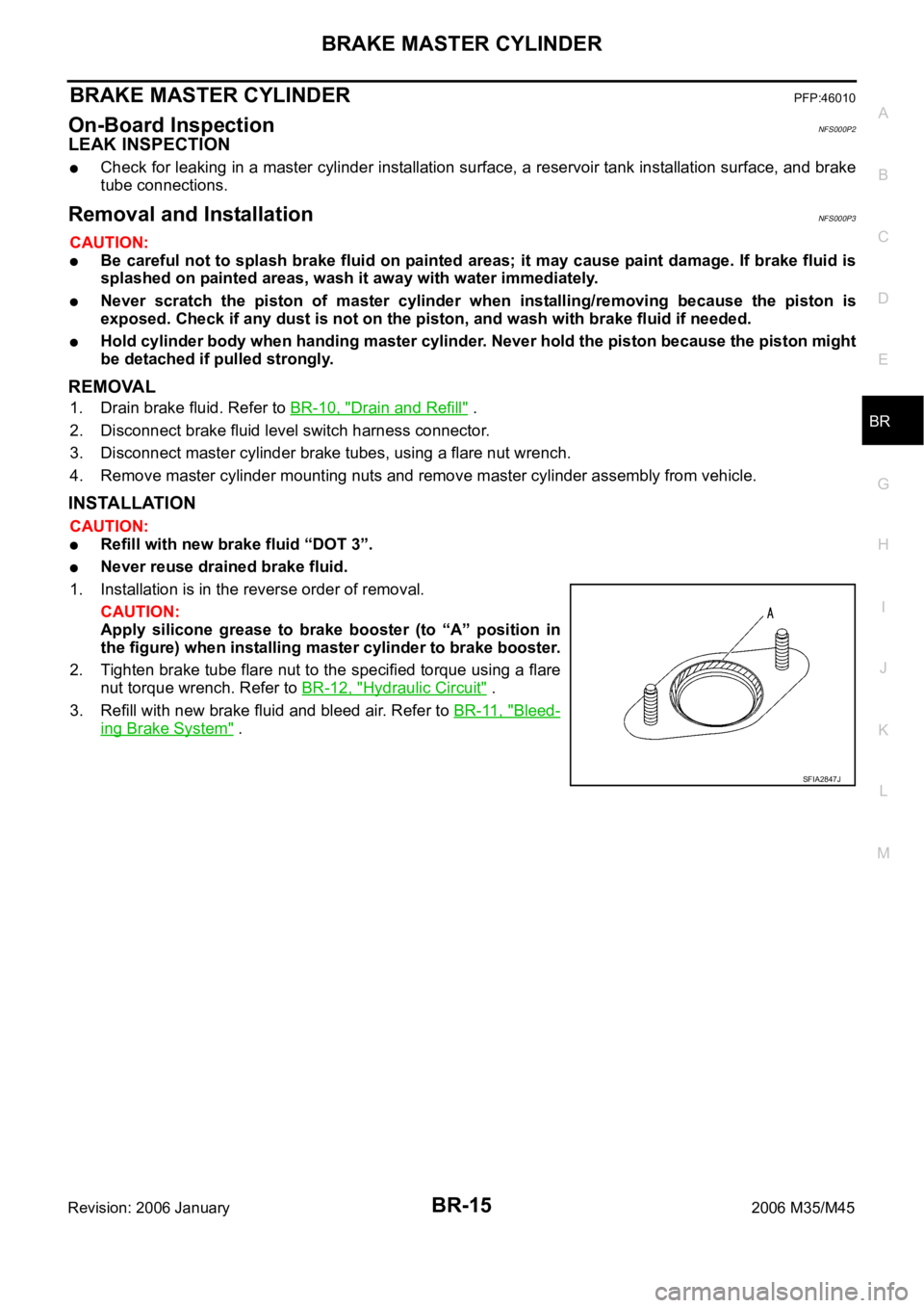
Apply silicone grease to brake booster (to “A” position in
the figure) when installing master cylinder to brake booster.
2. Tighten brake tube flare nut to the specified torque using a flare
nut torque wrench. Refer to BR-12, "
Hydraulic Circuit" .
3. Refill with new brake fluid and bleed air. Refer to BR-11, "
Bleed-
ing Brake System" .
SFIA2847J
Page 1291 of 5621
BR-16
BRAKE MASTER CYLINDER
Revision: 2006 January2006 M35/M45
Disassembly and AssemblyNFS000P4
COMPONENTS
Disassembly and AssemblyNFS000P5
DISASSEMBLY
CAUTION:
Master cylinder cannot be disassembled.
Remove reservoir tank only when absolutely necessary.
When securing master cylinder assembly in a vise, be sure not to over-tighten.
When securing in a vise use copper plates or cloth to protect the flange.
1. Using a pin punch [commercial service tool: diameter approxi-
mately 4 mm (0.16 in)], remove mounting pin on reservoir tank.
2. Remove reservoir tank and grommet from cylinder body.
1. Reservoir cap 2. Oil strainer 3. Reservoir tank
4. Grommet 5. Pin 6. Master cylinder assembly
7. O-ring 8. Brake fluid level switch connector
: PBC (Poly Butyl Cuprysil) grease
or silicone-based grease: Brake fluid
Refer to GI section for symbol marks except in the above.
SFIA2955E
BRA0559D