Page 4337 of 4462

TROUBLE DIAGNOSIS FOR SYMPTOMS TF-35
C E F
G H
I
J
K L
M A
B
TF
Revision: 2006 December 2006 FX35/FX45
4. CHECK AWD CONTROL UNIT
Check AWD control unit input/output signal. Refer to TF-20, "
AWD Control Unit Input/Output Signal Reference
Va l u e s" .
OK or NG
OK >> GO TO 5.
NG >> Check AWD control unit pin terminals for damage or loose connection with harness connector. If any items are damaged, repair or replace damaged parts.
5. CHECK OUTPUT SIGNAL WITH UNIFIED METER AND A/C AMP.
With CONSULT-II
1. Turn ignition switch “ON”. (Do not start engine.)
2. Select “DATA MONITOR” mode for “METER A/C AMP” with CONSULT-II.
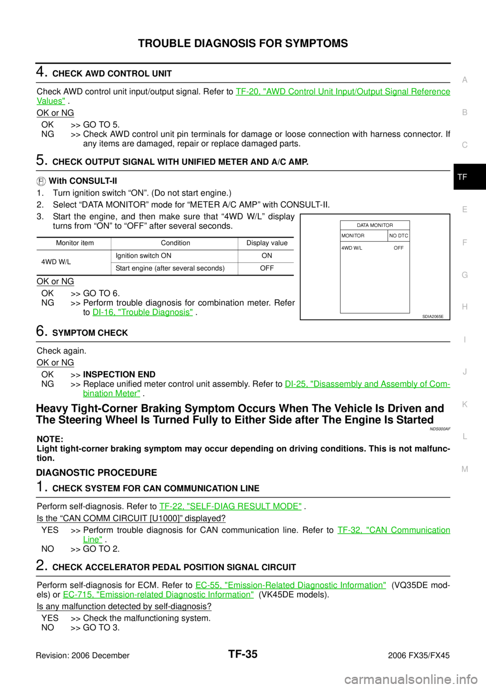
3. Start the engine, and then make sure that “4WD W/L” display turns from “ON” to “OFF” after several seconds.
OK or NG
OK >> GO TO 6.
NG >> Perform trouble diagnosis for combination meter. Refer to DI-16, "
Trouble Diagnosis" .
6. SYMPTOM CHECK
Check again.
OK or NG
OK >> INSPECTION END
NG >> Replace unified meter control unit assembly. Refer to DI-25, "
Disassembly and Assembly of Com-
bination Meter" .
Heavy Tight-Corner Braking Symptom Occurs When The Vehicle Is Driven and
The Steering Wheel Is Turned Fully to Either Side after The Engine Is Started
NDS000AF
NOTE:
Light tight-corner braking symptom may occur depending on driving conditions. This is not malfunc-
tion.
DIAGNOSTIC PROCEDURE
1. CHECK SYSTEM FOR CAN COMMUNICATION LINE
Perform self-diagnosis. Refer to TF-22, "
SELF-DIAG RESULT MODE" .
Is the
“CAN COMM CIRCUIT [U1000]” displayed?
YES >> Perform trouble diagnosis for CAN communication line. Refer to TF-32, "CAN Communication
Line" .
NO >> GO TO 2.
2. CHECK ACCELERATOR PEDAL POSITION SIGNAL CIRCUIT
Perform self-diagnosis for ECM. Refer to EC-55, "
Emission-Related Diagnostic Information" (VQ35DE mod-
els) or EC-715, "
Emission-related Diagnostic Information" (VK45DE models).
Is any malfunction detected by self-diagnosis?
YES >> Check the malfunctioning system.
NO >> GO TO 3.
Monitor item Condition Display value
4WD W/L Ignition switch ON ON
Start engine (after several seconds) OFF
SDIA2065E
Page 4339 of 4462

TROUBLE DIAGNOSIS FOR SYMPTOMS TF-37
C E F
G H
I
J
K L
M A
B
TF
Revision: 2006 December 2006 FX35/FX45
3. SYMPTOM CHECK
Check again.
OK or NG
OK >> INSPECTION END
NG >> Replace electric controlled coupling for mechanical malfunction (mechanical engagement of
clutch is not possible.). Refer to TF-45, "
Disassembly and Assembly" .
While Driving, AWD Warning Lamp Flashes Rapidly (When Flashing in Approx.
1 Minute and Then Turning OFF)
NDS000AH
NOTE:
Rapid flashing: 2 times/second
This symptom protects drivetrain parts when a heavy load is applied to the electric controlled coupling and
multiple disc clutch temperature increases. Also, optional distribution of torque sometimes becomes rigid
before lamp flashes rapidly. Both cases are not malfunction.
When this symptom occurs, stop vehicle and allow it to idle for some times. Flashing will stop and system will
be restored.
While Driving, AWD Warning Lamp Flashes Slowly (When Continuing to Flash
until Turning Ignition Switch OFF)
NDS000AI
NOTE:
Slow flashing: 1 time/2 seconds
DIAGNOSTIC PROCEDURE
1. CHECK TIRE
Check the following.
�Tire pressure
�Wear condition
�Longitudinal tire size (There is no difference between longitudinal tires.)
OK or NG
OK >> GO TO 2.
NG >> Drive at vehicle speed of 20 km/h (12 MPH) or more for 5 seconds or more after repairing or
replacing damaged parts. (Initialize improper size tire information.)
2. CHECK INPUT SIGNAL OF TIRE DIAMETER
With CONSULT-II
1. Start engine.
2. Drive at 20 km/h (12 MPH) or more for approx. 200 seconds.
3. Select “DATA MONITOR” mode for “ALL MODE AWD/4WD” with CONSULT-II.
4. Check monitor “DIS-TIRE MONI”.
Display of
“DIS-TIRE MONI”
“0-4mm”>> INSPECTION END
Except for “0-4mm”>>GO TO 3.
SDIA1900E
Page 4346 of 4462

TF-44
TRANSFER ASSEMBLY
Revision: 2006 December 2006 FX35/FX45
TRANSFER ASSEMBLYPFP:33100
Removal and InstallationNDS000AN
REMOVAL
1. Remove tunnel stay with power tool. Refer to RSU-7, "Removal and installation" .
2. Remove exhaust front tube with power tool. Refer to EX-3, "
EXHAUST SYSTEM" .
3. Remove front and rear propeller shaft. Refer to PR-4, "
FRONT PROPELLER SHAFT" and PR-7, "REAR
PROPELLER SHAFT" .
4. Disconnect transfer assembly harness connector and separate harness from transfer assembly.
5. Remove air breather hose. Refer to TF-43, "
AIR BREATHER HOSE" .
6. Support transfer assembly and transmission assembly with a jack.
7. Remove engine rear member with power tool. Refer to EM-113, "
ENGINE ASSEMBLY" (VQ35DE) or
EM-243, "
ENGINE ASSEMBLY" (VK45DE).
8. Remove transfer mounting bolts and separate transfer from transmission. CAUTION:
Secure transfer assembly to a jack.
INSTALLATION
Note the following, and install in the reverse order of removal.
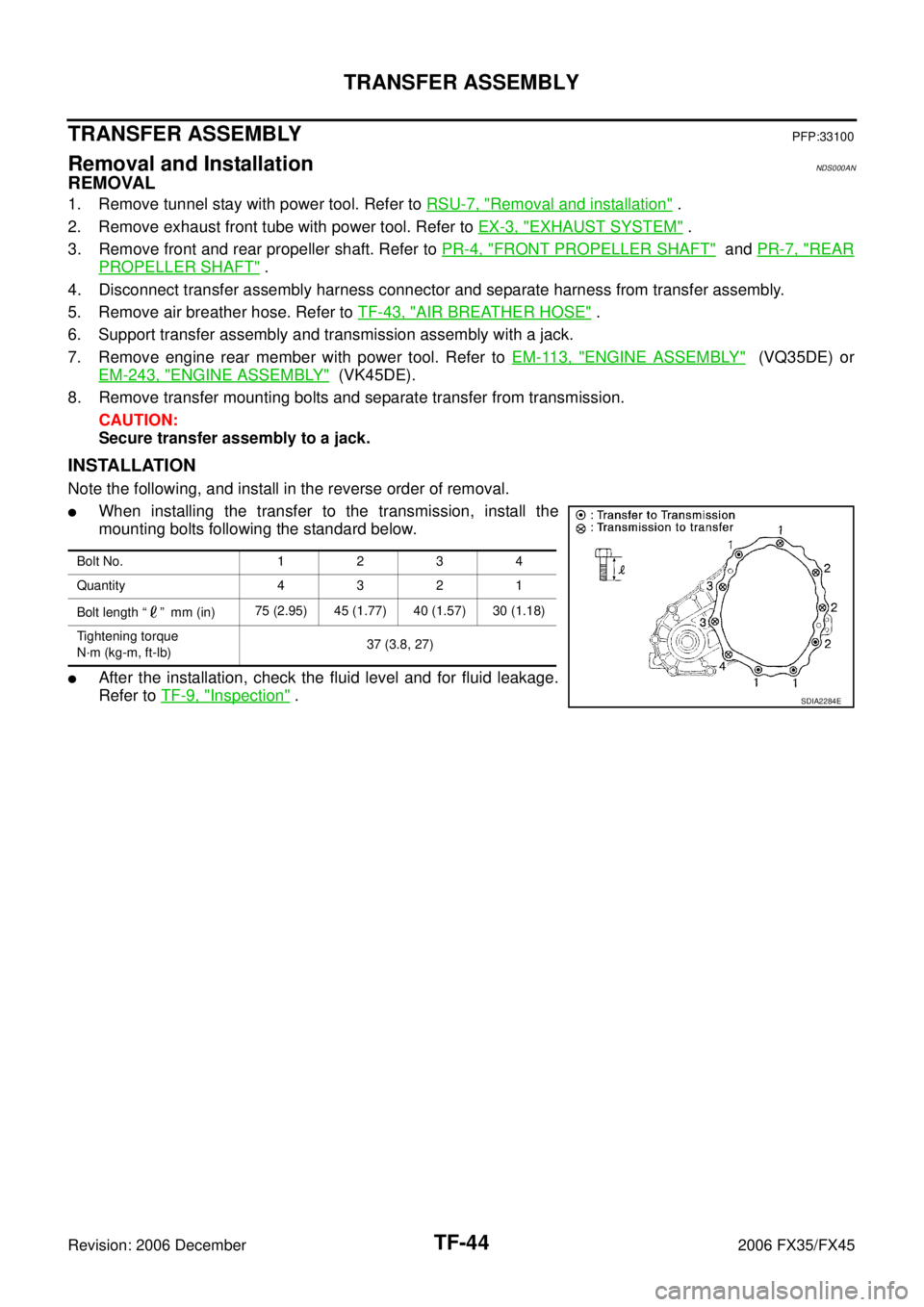
�When installing the transfer to the transmission, install the
mounting bolts following the standard below.
�After the installation, check the fluid level and for fluid leakage.
Refer to TF-9, "
Inspection" .
Bolt No. 1 2 3 4
Quantity 4 3 2 1
Bolt length “ ” mm (in) 75 (2.95) 45 (1.77) 40 (1.57) 30 (1.18)
Tightening torque
N·m (kg-m, ft-lb) 37 (3.8, 27)
SDIA2284E