Page 3937 of 4462
NOISE, VIBRATION AND HARSHNESS (NVH) TROUBLESHOOTING PR-3
C E F
G H
I
J
K L
M A
B
PR
Revision: 2006 December 2006 FX35/FX45
NOISE, VIBRATION AND HARSHNESS (NVH) TROUBLESHOOTINGPFP:00003
NVH Troubleshooting ChartNDS000AS
Use the chart below to help you find the cause of the symptom. If necessary, repair or replace these parts.
× : Applicable
Reference page
Front
PR-4—
—
—
—
PR-4PR-5
NVH in FFD and RFD section
NVH in FAX, RAX, FSU, and RSU section
NVH in WT section
NVH in WT section
NVH in RAX section
NVH in BR section
NVH in PS section
RearPR-7PR-11—
PR-8—
PR-7PR-10
Possible cause and SUSPECTED PARTS
Uneven rotating torque
Center bearing improper installation
Excessive center bearing axial end play
Center bearing mounting (insulator) cracks, damage or deterioration
Excessive joint angle
Rotation imbalance
Excessive runout
DIFFERENTIAL
AXLE AND SUSPENSION
TIRES
ROAD WHEEL
DRIVE SHAFT
BRAKES
STEERING
Symptom Noise
××××××××××××××
Shake × × ××××××
Vibration ××××××× ×× × ×
Page 3939 of 4462
FRONT PROPELLER SHAFT PR-5
C E F
G H
I
J
K L
M A
B
PR
Revision: 2006 December 2006 FX35/FX45
Removal and InstallationNDS000AV
REMOVAL
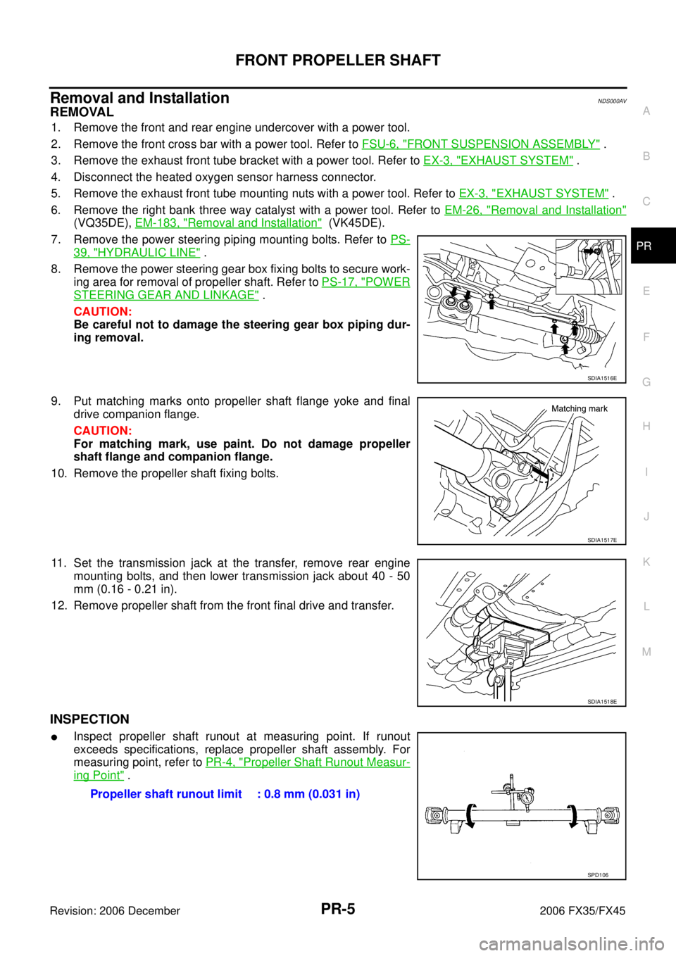
1. Remove the front and rear engine undercover with a power tool.
2. Remove the front cross bar with a power tool. Refer to FSU-6, "
FRONT SUSPENSION ASSEMBLY" .
3. Remove the exhaust front tube bracket with a power tool. Refer to EX-3, "
EXHAUST SYSTEM" .
4. Disconnect the heated oxygen sensor harness connector.
5. Remove the exhaust front tube mounting nuts with a power tool. Refer to EX-3, "
EXHAUST SYSTEM" .
6. Remove the right bank three way catalyst with a power tool. Refer to EM-26, "
Removal and Installation"
(VQ35DE), EM-183, "Removal and Installation" (VK45DE).
7. Remove the power steering piping mounting bolts. Refer to PS-
39, "HYDRAULIC LINE" .
8. Remove the power steering gear box fixing bolts to secure work- ing area for removal of propeller shaft. Refer to PS-17, "
POWER
STEERING GEAR AND LINKAGE" .
CAUTION:
Be careful not to damage the steering gear box piping dur-
ing removal.
9. Put matching marks onto propeller shaft flange yoke and final drive companion flange.
CAUTION:
For matching mark, use paint. Do not damage propeller
shaft flange and companion flange.
10. Remove the propeller shaft fixing bolts.
11. Set the transmission jack at the transfer, remove rear engine mounting bolts, and then lower transmission jack about 40 - 50
mm (0.16 - 0.21 in).
12. Remove propeller shaft from the front final drive and transfer.
INSPECTION
�Inspect propeller shaft runout at measuring point. If runout
exceeds specifications, replace propeller shaft assembly. For
measuring point, refer to PR-4, "
Propeller Shaft Runout Measur-
ing Point" .
SDIA1516E
SDIA1517E
SDIA1518E
Propeller shaft runout limit : 0.8 mm (0.031 in)
SPD106
Page 3943 of 4462
REAR PROPELLER SHAFT PR-9
C E F
G H
I
J
K L
M A
B
PR
Revision: 2006 December 2006 FX35/FX45
Removal and InstallationNDS000AY
REMOVAL
1. Move the A/T select lever to N position and release the parking brake.
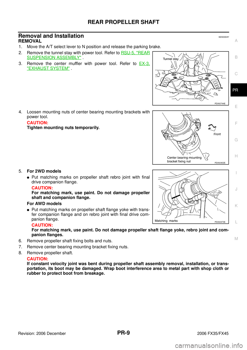
2. Remove the tunnel stay with power tool. Refer to RSU-5, "
REAR
SUSPENSION ASSEMBLY" .
3. Remove the center muffler with power tool. Refer to EX-3,
"EXHAUST SYSTEM" .
4. Loosen mounting nuts of center bearing mounting brackets with power tool.
CAUTION:
Tighten mounting nuts temporarily.
5. For 2WD models
�Put matching marks on propeller shaft rebro joint with final
drive companion flange.
CAUTION:
For matching mark, use paint. Do not damage propeller
shaft and companion flange.
For AWD models
�Put matching marks on propeller shaft flange yoke with trans-
fer companion flange and on rebro joint with final drive com-
panion flange.
CAUTION:
For matching mark, use paint. Do not damage propeller shaft flange yoke, rebro joint and com-
panion flanges.
6. Remove propeller shaft fixing bolts and nuts.
7. Remove center bearing mounting bracket fixing nuts.
8. Remove propeller shaft.
CAUTION:
If constant velocity joint was bent during propeller shaft assembly removal, installation, or trans-
portation, its boot may be damaged. Wrap boot interference area to metal part with shop cloth or
rubber to protect boot from breakage.
PDIA0744E
PDIA0402E
PDIA0470E
Page 3955 of 4462
NOISE, VIBRATION AND HARSHNESS (NVH) TROUBLESHOOTING PS-7
C
D E
F
H I
J
K L
M A
B
PS
Revision: 2006 December 2006 FX35/FX45
NOISE, VIBRATION AND HARSHNESS (NVH) TROUBLESHOOTINGPFP:00003
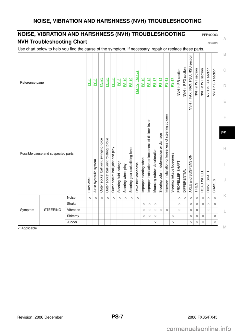
NVH Troubleshooting ChartNGS000BS
Use chart below to help you find the cause of the symptom. If necessary, repair or replace these parts.
× : Applicable Reference page
PS-8PS-8PS-23PS-23PS-23PS-8PS-10PS-10
EM-15
,
EM-174PS-10PS-12PS-17PS-12PS-12PS-17
NVH in PR section
NVH in RFD section
NVH in FAX, RAX, FSU, RSU section NVH in WT section
NVH in WT section
NVH in FAX section
NVH in BR section
Possible cause and suspected parts
Fluid level
Air in hydraulic system
Outer socket ball joint swinging force
Outer socket ball joint rotating torque
Outer socket ball joint end play
Steering fluid leakage
Steering wheel play
Steering gear rack sliding force
Drive belt looseness
Improper steering wheel
Improper installation or looseness of tilt lock lever
Mounting rubber deterioration
Steering column deformation or damage
Improper installation or looseness of steering column
Steering linkage looseness
PROPELLER SHAFT
DIFFERENTIAL
AXLE and SUSPENSION
TIRES
ROAD WHEEL
DRIVE SHAFT
BRAKES
Symptom STEERING Noise
× × ××××× × × ×××××× ×
Shake ××× × ×××× ×
Vibration ××××× × ×× ×
Shimmy ××× × ××× ×
Judder ××××××
Page 3958 of 4462
PS-10
STEERING WHEEL
Revision: 2006 December 2006 FX35/FX45
STEERING WHEELPFP:48430
On-Vehicle Inspection and ServiceNGS000BW
CHECKING CONDITION OF INSTALLATION
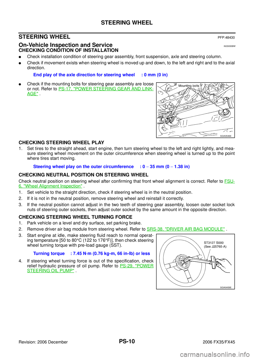
�Check installation condition of steering gear assembly, front suspension, axle and steering column.
�Check if movement exists when steering wheel is moved up and down, to the left and right and to the axial
direction.
�Check if the mounting bolts for steering gear assembly are loose
or not. Refer to PS-17, "
POWER STEERING GEAR AND LINK-
AGE" .
CHECKING STEERING WHEEL PLAY
1. Set tires to the straight ahead, start engine, then turn steering wheel to the left and right lightly, and mea-
sure steering wheel movement on the outer circumference when steering wheel is turned up to the point
where tires start moving.
CHECKING NEUTRAL POSITION ON STEERING WHEEL
Check neutral position on steering wheel after confirming that front wheel alignment is correct. Refer to FSU-
6, "Wheel Alignment Inspection" .
1. Set vehicle to the straight direction, check if steering wheel is in the neutral position.
2. If it is not in the neutral position, remove steering wheel and reinstall it correctly.
3. If the neutral position cannot adjust in the two teeth of steering gear assembly, loosen outer socket lock nuts of steering outer sockets, then adjust outer socket by the same amount in the opposite direction.
CHECKING STEERING WHEEL TURNING FORCE
1. Park vehicle on a level and dry surface, set parking brake.
2. Remove driver air bag module from steering wheel. Refer to SRS-38, "
DRIVER AIR BAG MODULE" .
3. Start engine at idle, make steering fluid reach to normal operat- ing temperature [50 to 80 °C (122 to 176 °F)], then check steering
wheel turning torque with pre-load gauge (SST).
4. If steering wheel turning force is out of the specification, check relief hydraulic pressure of oil pump. Refer to PS-29, "
POWER
STEERING OIL PUMP" .
End play of the axle direction for steering wheel : 0 mm (0 in)
SGIA0546E
Steering wheel play on the outer circumference : 0
− 35 mm (0 − 1.38 in)
Turning torque : 7.45 N·m (0.76 kg-m, 66 in-lb) or less
SGIA0459E
Page 3959 of 4462
STEERING WHEEL PS-11
C
D E
F
H I
J
K L
M A
B
PS
Revision: 2006 December 2006 FX35/FX45
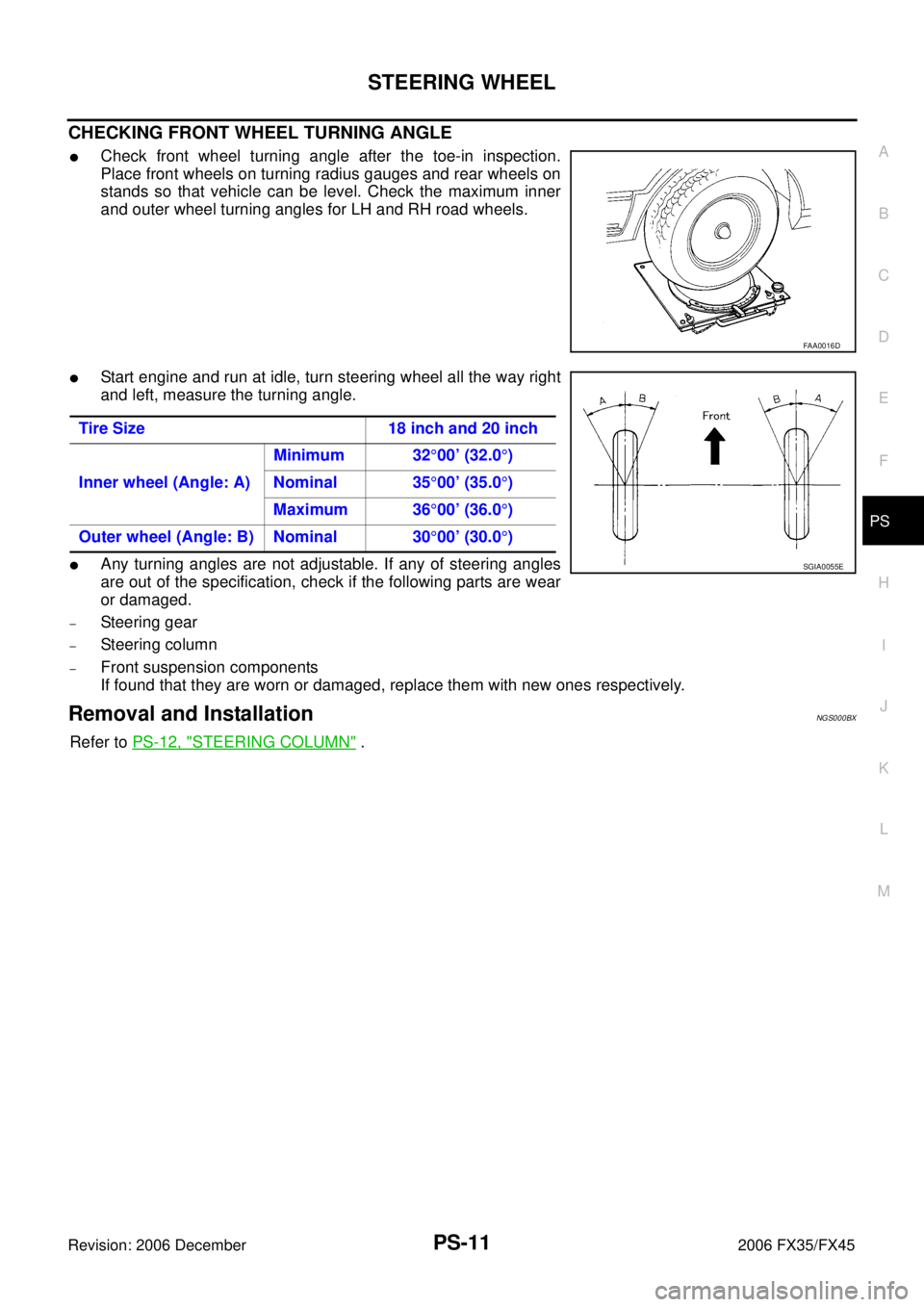
CHECKING FRONT WHEEL TURNING ANGLE
�Check front wheel turning angle after the toe-in inspection.
Place front wheels on turning radius gauges and rear wheels on
stands so that vehicle can be level. Check the maximum inner
and outer wheel turning angles for LH and RH road wheels.
�Start engine and run at idle, turn steering wheel all the way right
and left, measure the turning angle.
�Any turning angles are not adjustable. If any of steering angles
are out of the specification, check if the following parts are wear
or damaged.
–Steering gear
–St ee rin g c o lum n
–Front suspension components
If found that they are worn or damaged, replace them with new ones respectively.
Removal and InstallationNGS000BX
Refer to PS-12, "STEERING COLUMN" .
FAA0016D
Tire Size 18 inch and 20 inch
Inner wheel (Angle: A) Minimum 32
°00’ (32.0 °)
Nominal 35 °00’ (35.0 °)
Maximum 36 °00’ (36.0 °)
Outer wheel (Angle: B) Nominal 30 °00’ (30.0 °)
SGIA0055E
Page 3997 of 4462
PREPARATION RAX-3
C E F
G H
I
J
K L
M A
B
RAX
Revision: 2006 December 2006 FX35/FX45
PREPARATIONPFP:00002
Special Service Tools (SST)NDS000CE
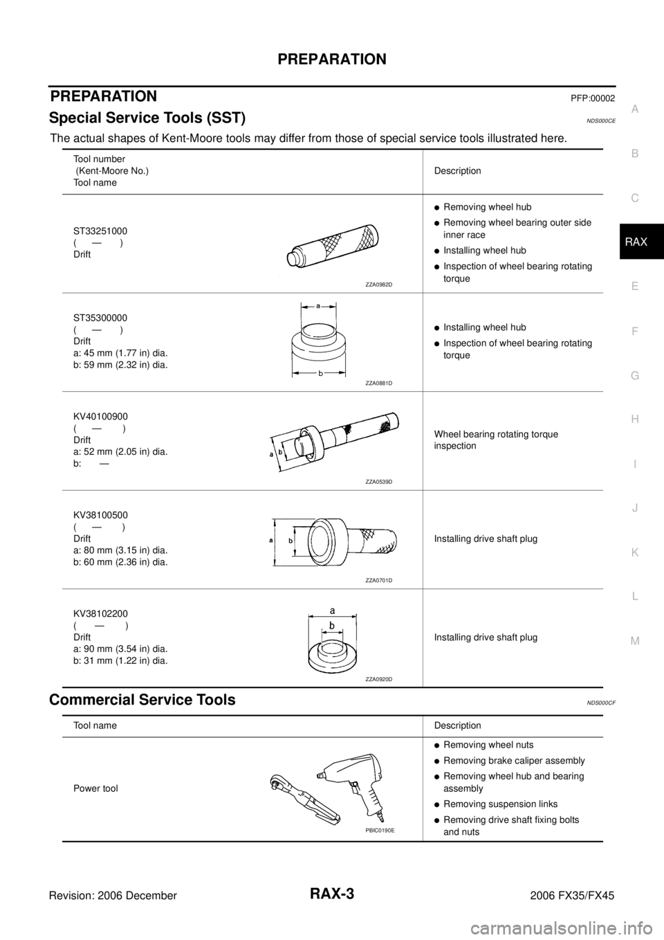
The actual shapes of Kent-Moore tools may differ from those of special service tools illustrated here.
Commercial Service ToolsNDS000CF
Tool number
(Kent-Moore No.)
Tool name Description
ST33251000
( — )
Drift
�Removing wheel hub
�Removing wheel bearing outer side
inner race
�Installing wheel hub
�Inspection of wheel bearing rotating
torque
ST35300000
( — )
Drift
a: 45 mm (1.77 in) dia.
b: 59 mm (2.32 in) dia.
�Installing wheel hub
�Inspection of wheel bearing rotating
torque
KV40100900
( — )
Drift
a: 52 mm (2.05 in) dia.
b: — Wheel bearing rotating torque
inspection
KV38100500
( — )
Drift
a: 80 mm (3.15 in) dia.
b: 60 mm (2.36 in) dia. Installing drive shaft plug
KV38102200
( — )
Drift
a: 90 mm (3.54 in) dia.
b: 31 mm (1.22 in) dia. Installing drive shaft plug
ZZA0982D
ZZA0881D
ZZA0539D
ZZA0701D
ZZA0920D
Tool name
Description
Power tool
�Removing wheel nuts
�Removing brake caliper assembly
�Removing wheel hub and bearing
assembly
�Removing suspension links
�Removing drive shaft fixing bolts
and nutsPBIC0190E
Page 3998 of 4462

RAX-4
NOISE, VIBRATION AND HARSHNESS (NVH) TROUBLESHOOTING
Revision: 2006 December 2006 FX35/FX45
NOISE, VIBRATION AND HARSHNESS (NVH) TROUBLESHOOTINGPFP:00003
NVH Troubleshooting ChartNDS000CG
Use chart below to help you find the cause of the symptom. If necessary, repair or replace these parts.
× : Applicable Reference page
—
RAX-9—
RAX-5—
NVH in PR section
NVH in RFD section
NVH in RAX and RSU section
Refer to REAR AXLE in this chart. NVH in WT section
NVH in WT section
Refer to DRIVE SHAFT in this chart. NVH in BR section
NVH in PS section
Possible cause and SUSPECTED PARTS
Excessive joint angle
Joint sliding resistance
Imbalance
Improper installation, looseness
Parts interference
PROPELLER SHAFT
DIFFERENTIAL
REAR AXLE AND REAR SUSPENSION
REAR AXLE
TIRES
ROAD WHEEL
DRIVE SHAFT
BRAKES
STEERING
Symptom DRIVE
SHAFT Noise
×× ×××××× ××
Shake ×× ×××××××
REAR
AXLE Noise
×× ××× ×××××
Shake ×××××××××
Vibration ×××××××
Shimmy ×× ×××××
Judder × × ×× ××
Poor quality ride or handling ×× × ××