Page 846 of 4462
BL-32
POWER DOOR LOCK SYSTEM
Revision: 2006 December 2006 FX35/FX45
Wiring Diagram — D/LOCK —/Without Intelligent KeyNIS001M1
TIWM1653E
Page 873 of 4462
REMOTE KEYLESS ENTRY SYSTEM BL-59
C
D E
F
G H
J
K L
M A
B
BL
Revision: 2006 December 2006 FX35/FX45
Wiring Diagram — KEYLES —NIS001MM
TIWM1656E
Page 912 of 4462
BL-98
INTELLIGENT KEY SYSTEM
Revision: 2006 December 2006 FX35/FX45
Wiring Diagram — I/KEY —NIS001NA
TIWM1661E
Page 980 of 4462
BL-166
BACK DOOR AUTO CLOSURE SYSTEM
Revision: 2006 December 2006 FX35/FX45
Wiring Diagram — B/CLOS —NIS001OO
TIWM1712E
Page 1000 of 4462
BL-186
VEHICLE SECURITY (THEFT WARNING) SYSTEM
Revision: 2006 December 2006 FX35/FX45
Wiring Diagram — VEHSEC —NIS001P7
TIWM1673E
Page 1022 of 4462
BL-208
IVIS (INFINITI VEHICLE IMMOBILIZER SYSTEM-NATS)
Revision: 2006 December 2006 FX35/FX45
Wiring Diagram – NATS –NIS001PO
MODELS WITH INTELLIGENT KEY SYSTEM
TIWM1677E
Page 1041 of 4462
INTEGRATED HOMELINK TRANSMITTER BL-227
C
D E
F
G H
J
K L
M A
B
BL
Revision: 2006 December 2006 FX35/FX45
INTEGRATED HOMELINK TRANSMITTERPFP:96401
Wiring Diagram —TRNSCV—NIS001Q4
TIWM1680E
Page 1133 of 4462

BRC-1
BRAKE CONTROL SYSTEM
F BRAKES
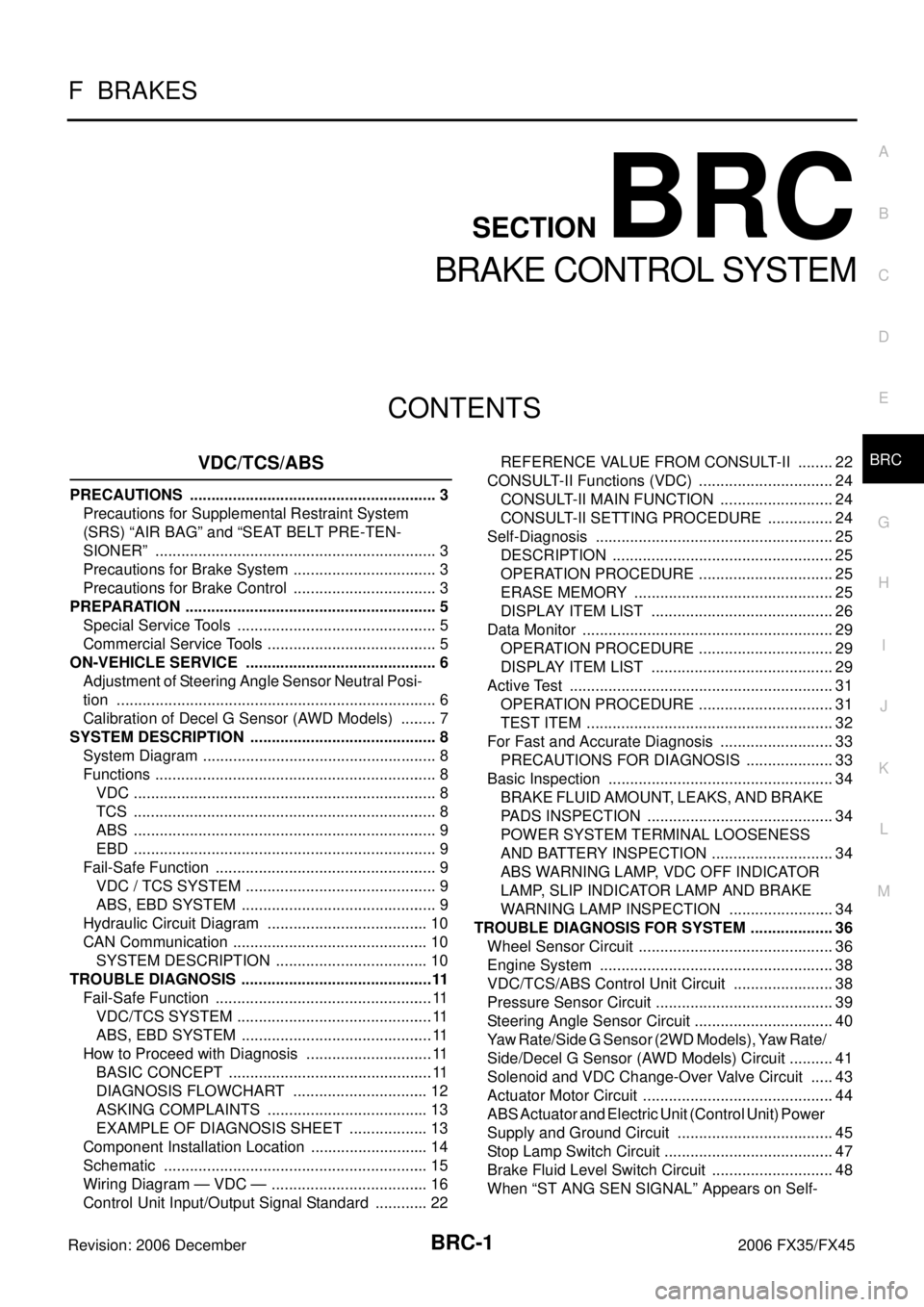
CONTENTS
C
D E
G H
I
J
K L
M
SECTION BRC
A
B
BRC
Revision: 2006 December 2006 FX35/FX45
BRAKE CONTROL SYSTEM
VDC/TCS/ABS
PRECAUTIONS ..................................................... ..... 3
Precautions for Supplemental Restraint System
(SRS) “AIR BAG” and “SEAT BELT PRE-TEN-
SIONER” ............................................................. ..... 3
Precautions for Brake System ............................. ..... 3
Precautions for Brake Control ............................. ..... 3
PREPARATION ...................................................... ..... 5
Special Service Tools .......................................... ..... 5
Commercial Service Tools ................................... ..... 5
ON-VEHICLE SERVICE ........................................ ..... 6
Adjustment of Steering Angle Sensor Neutral Posi-
tion ...................................................................... ..... 6
Calibration of Decel G Sensor (AWD Models) .... ..... 7
SYSTEM DESCRIPTION ....................................... ..... 8
System Diagram .................................................. ..... 8
Functions ............................................................. ..... 8
VDC .................................................................. ..... 8
TCS .................................................................. ..... 8
ABS .................................................................. ..... 9
EBD .................................................................. ..... 9
Fail-Safe Function ............................................... ..... 9
VDC / TCS SYSTEM ........................................ ..... 9
ABS, EBD SYSTEM ......................................... ..... 9
Hydraulic Circuit Diagram ................................... ... 10
CAN Communication ........................................... ... 10
SYSTEM DESCRIPTION ................................. ... 10
TROUBLE DIAGNOSIS ......................................... ....11
Fail-Safe Function ............................................... .... 11
VDC/TCS SYSTEM .......................................... .... 11
ABS, EBD SYSTEM ......................................... .... 11
How to Proceed with Diagnosis .......................... .... 11
BASIC CONCEPT ............................................ .... 11
DIAGNOSIS FLOWCHART ............................. ... 12
ASKING COMPLAINTS ................................... ... 13
EXAMPLE OF DIAGNOSIS SHEET ................ ... 13
Component Installation Location ......................... ... 14
Schematic ........................................................... ... 15
Wiring Diagram — VDC — .................................. ... 16
Control Unit Input/Output Signal Standard .......... ... 22 REFERENCE VALUE FROM CONSULT-II ......
... 22
CONSULT-II Functions (VDC) ............................. ... 24
CONSULT-II MAIN FUNCTION ........................ ... 24
CONSULT-II SETTING PROCEDURE ............. ... 24
Self-Diagnosis ..................................................... ... 25
DESCRIPTION ................................................. ... 25
OPERATION PROCEDURE ............................. ... 25
ERASE MEMORY ............................................ ... 25
DISPLAY ITEM LIST ........................................ ... 26
Data Monitor ........................................................ ... 29
OPERATION PROCEDURE ............................. ... 29
DISPLAY ITEM LIST ........................................ ... 29
Active Test ........................................................... ... 31
OPERATION PROCEDURE ............................. ... 31
TEST ITEM ....................................................... ... 32
For Fast and Accurate Diagnosis ........................ ... 33
PRECAUTIONS FOR DIAGNOSIS .................. ... 33
Basic Inspection .................................................. ... 34
BRAKE FLUID AMOUNT, LEAKS, AND BRAKE
PADS INSPECTION ......................................... ... 34
POWER SYSTEM TERMINAL LOOSENESS
AND BATTERY INSPECTION .......................... ... 34
ABS WARNING LAMP, VDC OFF INDICATOR
LAMP, SLIP INDICATOR LAMP AND BRAKE
WARNING LAMP INSPECTION ...................... ... 34
TROUBLE DIAGNOSIS FOR SYSTEM ................. ... 36
Wheel Sensor Circuit ........................................... ... 36
Engine System .................................................... ... 38
VDC/TCS/ABS Control Unit Circuit ..................... ... 38
Pressure Sensor Circuit ....................................... ... 39
Steering Angle Sensor Circuit .............................. ... 40
Yaw Rate/Side G Sensor (2WD Models), Yaw Rate/
Side/Decel G Sensor (AWD Models) Circuit ........ ... 41
Solenoid and VDC Change-Over Valve Circuit ... ... 43
Actuator Motor Circuit .......................................... ... 44
ABS Actuator and Electric Unit (Control Unit) Power
Supply and Ground Circuit .................................. ... 45
Stop Lamp Switch Circuit ..................................... ... 47
Brake Fluid Level Switch Circuit .......................... ... 48
When “ST ANG SEN SIGNAL” Appears on Self-