Page 1290 of 4462
DI-40
WARNING LAMPS
Revision: 2006 December 2006 FX35/FX45
Wiring Diagram — WARN —NKS0030D
TKWM4346E
Page 1303 of 4462
A/T INDICATOR DI-53
C
D E
F
G H
I
J
L
M A
B
DI
Revision: 2006 December 2006 FX35/FX45
Wiring Diagram — AT/IND —NKS0030H
TKWM4354E
Page 1311 of 4462
WARNING CHIME DI-61
C
D E
F
G H
I
J
L
M A
B
DI
Revision: 2006 December 2006 FX35/FX45
Wiring Diagram — CHIME —NKS0030O
TKWM4357E
Page 1332 of 4462

DI-82
LANE DEPARTURE WARNING SYSTEM
Revision: 2006 December 2006 FX35/FX45
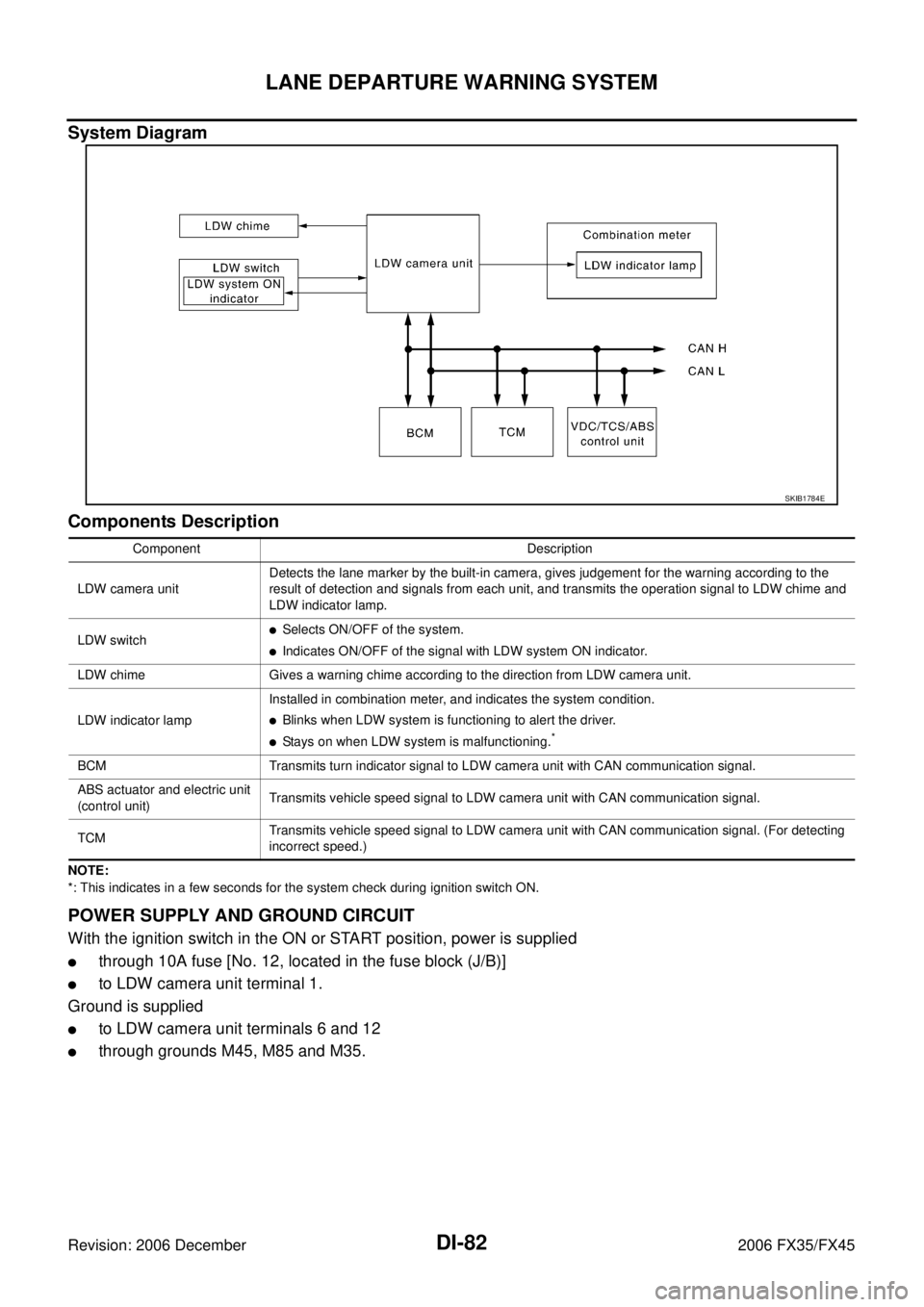
System Diagram
Components Description
NOTE:
*: This indicates in a few seconds for the system check during ignition switch ON.
POWER SUPPLY AND GROUND CIRCUIT
With the ignition switch in the ON or START position, power is supplied
�through 10A fuse [No. 12, located in the fuse block (J/B)]
�to LDW camera unit terminal 1.
Ground is supplied
�to LDW camera unit terminals 6 and 12
�through grounds M45, M85 and M35.
SKIB1784E
Component Description
LDW camera unit Detects the lane marker by the built-in camera, gives judgement for the warning according to the
result of detection and signals from each unit, and transmits the operation signal to LDW chime and
LDW indicator lamp.
LDW switch
�Selects ON/OFF of the system.
�Indicates ON/OFF of the signal with LDW system ON indicator.
LDW chime Gives a warning chime according to the direction from LDW camera unit.
LDW indicator lamp Installed in combination meter, and indicates the system condition.
�Blinks when LDW system is functioning to alert the driver.
�Stays on when LDW system is malfunctioning.*
BCM Transmits turn indicator signal to LDW camera unit with CAN communication signal.
ABS actuator and electric unit
(control unit) Transmits vehicle speed signal to LDW camera unit with CAN communication signal.
TCM Transmits vehicle speed signal to LDW camera unit with CAN communication signal. (For detecting
incorrect speed.)
Page 1342 of 4462
DI-92
LANE DEPARTURE WARNING SYSTEM
Revision: 2006 December 2006 FX35/FX45
Wiring Diagram — LDW —NKS00318
TKWM4367E
Page 1362 of 4462
DI-112
COMPASS
Revision: 2006 December 2006 FX35/FX45
Wiring Diagram — COMPAS —NKS003HV
TKWM4344E
Page 1364 of 4462
DI-114
CLOCK
Revision: 2006 December 2006 FX35/FX45
CLOCKPFP:25820
Wiring Diagram — CLOCK —NKS0031R
TKWM4360E
Page 1369 of 4462
REAR VIEW MONITOR DI-119
C
D E
F
G H
I
J
L
M A
B
DI
Revision: 2006 December 2006 FX35/FX45
Wiring Diagram — R/VIEW —NKS0031W
TKWM4362E