Page 955 of 4462

INTELLIGENT KEY SYSTEM BL-141
C
D E
F
G H
J
K L
M A
B
BL
Revision: 2006 December 2006 FX35/FX45
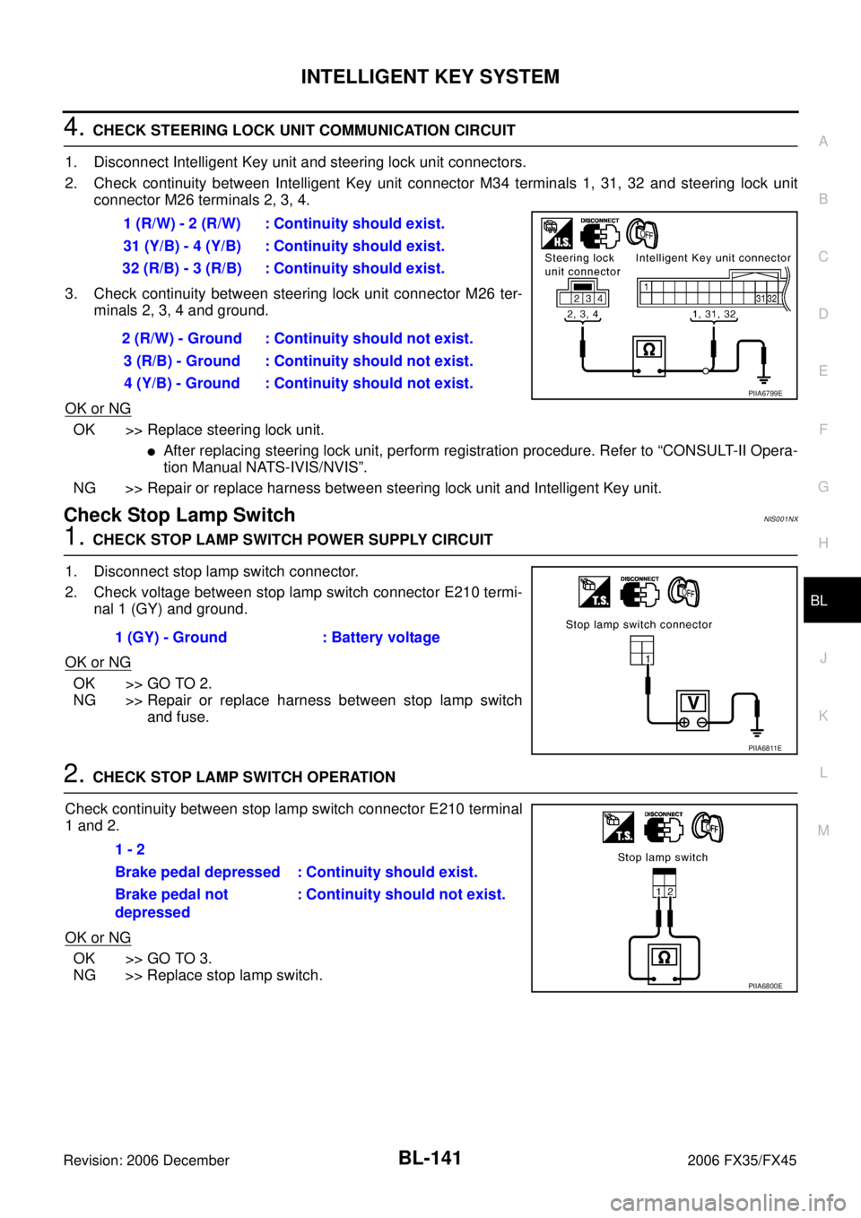
4. CHECK STEERING LOCK UNIT COMMUNICATION CIRCUIT
1. Disconnect Intelligent Key unit and steering lock unit connectors.
2. Check continuity between Intelligent Key unit connector M34 terminals 1, 31, 32 and steering lock unit connector M26 terminals 2, 3, 4.
3. Check continuity between steering lock unit connector M26 ter- minals 2, 3, 4 and ground.
OK or NG
OK >> Replace steering lock unit.
�After replacing steering lock unit, perform registration procedure. Refer to “CONSULT-II Opera-
tion Manual NATS-IVIS/NVIS”.
NG >> Repair or replace harness between steering lock unit and Intelligent Key unit.
Check Stop Lamp SwitchNIS001NX
1. CHECK STOP LAMP SWITCH POWER SUPPLY CIRCUIT
1. Disconnect stop lamp switch connector.
2. Check voltage between stop lamp switch connector E210 termi- nal 1 (GY) and ground.
OK or NG
OK >> GO TO 2.
NG >> Repair or replace harness between stop lamp switch and fuse.
2. CHECK STOP LAMP SWITCH OPERATION
Check continuity between stop lamp switch connector E210 terminal
1 and 2.
OK or NG
OK >> GO TO 3.
NG >> Replace stop lamp switch. 1 (R/W) - 2 (R/W) : Continuity should exist.
31 (Y/B) - 4 (Y/B) : Continuity should exist.
32 (R/B) - 3 (R/B) : Continuity should exist.
2 (R/W) - Ground : Continuity should not exist. 3 (R/B) - Ground : Continuity should not exist.4 (Y/B) - Ground : Continuity should not exist.
PIIA6799E
1 (GY) - Ground : Battery voltage
PIIA6811E
1 - 2
Brake pedal depressed : Continuity should exist.
Brake pedal not
depressed : Continuity should not exist.
PIIA6800E
Page 956 of 4462
BL-142
INTELLIGENT KEY SYSTEM
Revision: 2006 December 2006 FX35/FX45
3. CHECK STOP LAMP SWITCH GROUND CIRCUIT
1. Check continuity between stop lamp switch connector E210 ter- minal 2 (P) and Intelligent Key unit connector M34 terminal 26
(P/L).
2. Check continuity between stop lamp switch connector E210 ter- minal 2 (P) and ground.
OK or NG
OK >> Stop lamp switch is OK.
NG >> Repair or replace harness.
Check Detention SwitchNIS001NY
1. CHECK DETENTION SWITCH INPUT SIGNAL
1. Turn ignition knob LOCK position.
2. Check voltage between Intelligent Key unit connector and ground.
OK or NG
OK >> Door switch circuit is OK.
NG >> GO TO 2. 2 (P) - 26 (P/L) : Continuity should exist.
2 (P) - Ground : Continuity should not exist.
PIIA6801E
Connector Terminal
(Wire color) Condition Voltage (V)
(Approx.)
(+) (-)
M34 39 (R/Y) Ground When selector lever is locked
at the “P” position 0
When selector lever is not
locked at the “P” position Battery voltage
PIIA6805E
Page 957 of 4462
INTELLIGENT KEY SYSTEM BL-143
C
D E
F
G H
J
K L
M A
B
BL
Revision: 2006 December 2006 FX35/FX45
2. CHECK DETENTION SWITCH CIRCUIT
1. Disconnect A/T device (detention switch) connector.
2. Check voltage between A/T device (detention switch) connector M67 terminal 3 (R/Y) and ground. (Check harness for open.)
3. Check continuity between A/T device (detention switch) connec- tor M67 terminals 3 (R/Y) and ground. (Check harness for
short.)
OK or NG
OK >> GO TO 3.
NG >> Repair or replace harness.
3. CHECK DETENTION SWITCH
Check continuity between A/T device (detention switch) terminals 2 and 3.
OK or NG
OK >> GO TO 4.
NG >> Replace back A/T device (detention switch). 3 (R/Y) – Ground : Battery voltage
PIIA6806E
3 (R/Y) – Ground : Continuity should not exist.
PIIA6807E
Terminal Condition Continuity
23 When selector lever is not
locked at the “P” position No
When selector lever is
locked at the “P” position Ye s
PIIA6808E
Page 958 of 4462

BL-144
INTELLIGENT KEY SYSTEM
Revision: 2006 December 2006 FX35/FX45
4. DETENTION SWITCH GROUND CIRCUIT INSPECTION
Check continuity between A/T device (detention switch) connector
M67 terminal 2 (B) and ground.
OK or NG
OK >> Check harness connection.
NG >> Repair or replace harness.
Check Select Unlock RelayNIS001NZ
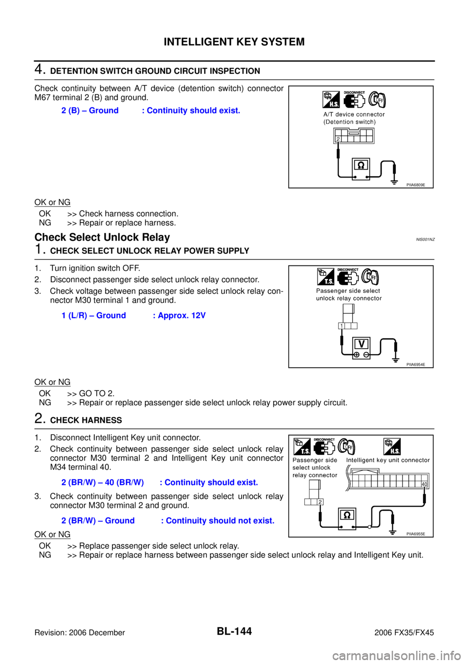
1. CHECK SELECT UNLOCK RELAY POWER SUPPLY
1. Turn ignition switch OFF.
2. Disconnect passenger side select unlock relay connector.
3. Check voltage between passenger side select unlock relay con- nector M30 terminal 1 and ground.
OK or NG
OK >> GO TO 2.
NG >> Repair or replace passenger side select unlock relay power supply circuit.
2. CHECK HARNESS
1. Disconnect Intelligent Key unit connector.
2. Check continuity between passenger side select unlock relay connector M30 terminal 2 and Intelligent Key unit connector
M34 terminal 40.
3. Check continuity between passenger side select unlock relay connector M30 terminal 2 and ground.
OK or NG
OK >> Replace passenger side select unlock relay.
NG >> Repair or replace harness between passenger side select unlock relay and Intelligent Key unit. 2 (B) – Ground : Continuity should exist.
PIIA6809E
1 (L/R) – Ground : Approx. 12V
PIIA6954E
2 (BR/W) – 40 (BR/W) : Continuity should exist.
2 (BR/W) – Ground : Continuity should not exist.
PIIA6955E
Page 959 of 4462

INTELLIGENT KEY SYSTEM BL-145
C
D E
F
G H
J
K L
M A
B
BL
Revision: 2006 December 2006 FX35/FX45
Check Hazard FunctionNIS001O0
1. CHECK HAZARD WARNING LAMP
Does hazard warning lamp flash with hazard switch?
YES or NO
YES >> Hazard warning lamp circuit is OK.
NO >> Check hazard circuit. Refer to LT- 9 0 , "
TURN SIGNAL AND HAZARD WARNING LAMPS" .
Check Horn FunctionNIS001O1
First perform the “SELF-DIAG RESULTS” in “BCM” with CONSULT-II, then perform the trouble diagnosis of
malfunction system indicated “SELF-DIAG RESULTS” of “BCM”. Refer to BCS-14, "
CAN Communication
Inspection Using CONSULT-II (Self-Diagnosis)" .
1. CHECK HORN FUNCTION
Does horn sound with horn switch?
YES or NO
YES >> Horn circuit is OK.
NO >> Check horn circuit. Refer to WW-58, "
HORN" .
Check Headlamp FunctionNIS001O2
First perform the “SELF-DIAG RESULTS” in “BCM” with CONSULT-II, then perform the trouble diagnosis of
malfunction system indicated “SELF-DIAG RESULTS” of “BCM”. Refer to BCS-14, "
CAN Communication
Inspection Using CONSULT-II (Self-Diagnosis)" .
1. CHECK HEADLAMP OPERATION
Does headlamp come on when turning lighting switch “ON”?
YES or NO
YES >> Headlamp operation circuit is OK.
NO >> Check headlamp system. Refer to LT- 7 , "
HEADLAMP - XENON TYPE -" .
Check IPDM E/R OperationNIS001O3
1. CHECK IPDM E/R INPUT VOLTAGE
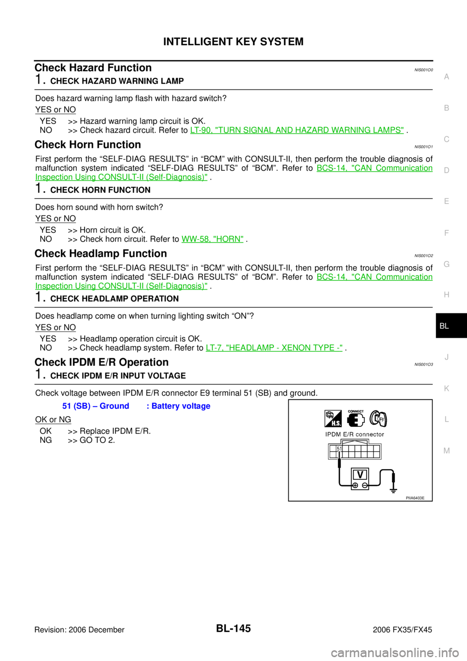
Check voltage between IPDM E/R connector E9 terminal 51 (SB) and ground.
OK or NG
OK >> Replace IPDM E/R.
NG >> GO TO 2. 51 (SB) – Ground : Battery voltage
PIIA6403E
Page 960 of 4462
BL-146
INTELLIGENT KEY SYSTEM
Revision: 2006 December 2006 FX35/FX45
2. CHECK IPDM E/R HARNESS
1. Turn ignition switch OFF.
2. Disconnect IPDM E/R and horn relay connector.
3. Check continuity between IPDM E/R connector E9 terminal 51 (SB) and horn relay connector E10 termi- nal 1 (SB).
OK or NG
OK >> Check harness connection.
NG >> Repair or replace harness.
Removal and Installation of Intelligent Key UnitNIS001O4
REMOVAL
1. Remove the instrument lower driver panel. Refer to IP-11, "Removal and Installation" .
2. Disconnect the Intelligent Key unit connector, remove the screw and Intelligent Key unit.
INSTALLATION
Install in the reverse order of removal. 51 (SB) – 1 (SB) : Continuity should exist.
PIIA6404E
PIIA6371E
Page 961 of 4462
INTELLIGENT KEY SYSTEM BL-147
C
D E
F
G H
J
K L
M A
B
BL
Revision: 2006 December 2006 FX35/FX45
Intelligent Key Battery ReplacementNIS001O5
INTELLIGENT KEY BATTERY INSPECTION
Check by connecting a resistance (approximately 300 Ω) so that the
current value becomes about 10 mA.
PIIB4646E
Standard : Approx. 2.5V - 3.0V
OCC0607D
Page 978 of 4462

BL-164
BACK DOOR AUTO CLOSURE SYSTEM
Revision: 2006 December 2006 FX35/FX45
BACK DOOR AUTO CLOSURE SYSTEMPFP:90542
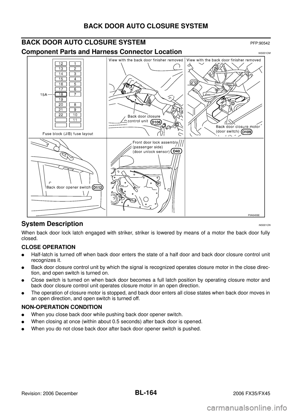
Component Parts and Harness Connector LocationNIS001OM
System DescriptionNIS001ON
When back door lock latch engaged with striker, striker is lowered by means of a motor the back door fully
closed.
CLOSE OPERATION
�Half-latch is turned off when back door enters the state of a half door and back door closure control unit
recognizes it.
�Back door closure control unit by which the signal is recognized operates closure motor in the close direc-
tion, and open switch is turned on.
�Close switch is turned on when back door becomes a full latch position by operating closure motor and
back door closure control unit operates closure motor in an open direction.
�The operation of closure motor is stopped, and back door enters all close states when back door moves in
an open direction, and open switch is turned off.
NON-OPERATION CONDITION
�When you close back door while pushing back door opener switch.
�When closing at once (within about 0.5 seconds) after back door is opened.
�When you do not close back door after back door opener switch is pushed.
PIIA6406E