Page 2958 of 4462
![INFINITI FX35 2006 Service Manual EM-164
[VK45DE]
PRECAUTIONS
Revision: 2006 December 2006 FX35/FX45
[VK45DE]PRECAUTIONSPFP:00001
Precautions Necessary for Steering Wheel Rotation After Battery DisconnectNBS003HA
NOTE:
�This Procedure](/manual-img/42/57019/w960_57019-2957.png "INFINITI FX35 2006 Service Manual EM-164
[VK45DE]
PRECAUTIONS
Revision: 2006 December 2006 FX35/FX45
[VK45DE]PRECAUTIONSPFP:00001
Precautions Necessary for Steering Wheel Rotation After Battery DisconnectNBS003HA
NOTE:
�This Procedure")
EM-164
[VK45DE]
PRECAUTIONS
Revision: 2006 December 2006 FX35/FX45
[VK45DE]PRECAUTIONSPFP:00001
Precautions Necessary for Steering Wheel Rotation After Battery DisconnectNBS003HA
NOTE:
�This Procedure is applied only to models with Intelligent Key system ang NVIS/IVIS (NISSAN/INFINITI
VEHICLE IMMOBILIZER SYSTEM - NATS).
�Remove and install all control units after disconnecting both battery cables with the ignition knob in the
″ LOCK ″ position.
�Always use CONSULT-II to perform self-diagnosis as a part of each function inspection after finishing
work. If DTC is detected, perform trouble diagnosis according to self-diagnosis results.
For models equipped with the Intelligent Key system and NVIS/IVIS, an electrically controlled steering lock
mechanism is adopted on the key cylinder.
For this reason, if the battery is disconnected or if the battery is discharged, the steering wheel will lock and
steering wheel rotation will become impossible.
If steering wheel rotation is required when battery power is interrupted, follow the procedure below before
starting the repair operation.
OPERATION PROCEDURE
1. Connect both battery cables.
NOTE:
Supply power using jumper cables if battery is discharged.
2. Use the Intelligent Key or mechanical key to turn the ignition switch to the ″ACC ″ position. At this time, the
steering lock will be released.
3. Disconnect both battery cables. The steering lock will remain released and the steering wheel can be rotated.
4. Perform the necessary repair operation.
5. When the repair work is completed, return the ignition switch to the ″LOCK ″ position before connecting
the battery cables. (At this time, the steering lock mechanism will engage.)
6. Perform a self-diagnosis check of all control units using CONSULT-II.
Precautions for Drain Engine Coolant and Engine OilNBS003HB
Drain engine coolant and engine oil when engine is cooled.
Precautions for Disconnecting Fuel PipingNBS003HC
�Before starting work, make sure no fire or spark producing items are in the work area.
�Release fuel pressure before disconnecting and disassembly.
�After disconnecting pipes, plug openings to stop fuel leakage.
Precautions for Removal and DisassemblyNBS003HD
�When instructed to use SST, use specified tools. Always be careful to work safely, avoid forceful or unin-
structed operations.
�Exercise maximum care to avoid damage to mating or sliding surfaces.
�Cover openings of engine system with tape or the equivalent, if necessary, to seal out foreign materials.
�Mark and arrange disassembly parts in an organized way for easy troubleshooting and assembly.
�When loosening nuts and bolts, as a basic rule, start with the one furthest outside, then the one diagonally
opposite, and so on. If the order of loosening is specified, do exactly as specified. Power tools may be
used where noted in the step.
Precautions for Inspection, Repair and ReplacementNBS003HE
Before repairing or replacing, thoroughly inspect parts. Inspect new replacement parts in the same way, and
replace if necessary.
Precautions for Assembly and InstallationNBS003HF
�Use torque wrench to tighten bolts or nuts to specification.
Page 2963 of 4462
PREPARATION EM-169
[VK45DE]
C
D E
F
G H
I
J
K L
M A
EM
Revision: 2006 December 2006 FX35/FX45
Commercial Service ToolsNBS003HJ
—
(J-45476)
Ring gear stopper Removing and installing crankshaft pulley
—
(J-45488)
Quick connector release Removing fuel tube quick connectors in
engine room
Tool number
(Kent-Moore No.)
Tool name Description
PBIC1655E
PBIC0198E
(Kent-Moore No.)
Tool name Description
(—)
Power tool Loosening nuts and bolts
(—)
Spark plug wrench Removing and installing spark plug
(—)
Manual lift table caddy Removing and installing engine
(J–24239-01)
Cylinder head bolt wrench Loosening and tightening cylinder head bolt,
and use with angle wrench [SST:
KV10112100 (BT–8653-A)]
a: 13 (0.51) dia.
b: 12 (0.47)
c: 10 (0.39)
Unit: mm (in)
PBIC0190E
S-NT047
ZZA1210D
NT583
Page 2985 of 4462
IGNITION COIL EM-191
[VK45DE]
C
D E
F
G H
I
J
K L
M A
EM
Revision: 2006 December 2006 FX35/FX45
IGNITION COILPFP:22448
ComponentsNBS003I3
Removal and InstallationNBS003I4
REMOVAL
1. Remove engine cover with power tool. Refer to EM-173, "ENGINE ROOM COVER" .
2. Remove air duct (inlet), air cleaner case and mass air flow sensor assembly, air duct and resonator assembly. Refer to EM-177, "
AIR CLEANER AND AIR DUCT" .
3. Disconnect harness connector from ignition coil.
4. Remove ignition coil. CAUTION:
Do not shock it.
INSTALLATION
Install in the reverse order of removal.
1. Ignition coil 2. Spark plug
PBIC1589E
Page 2986 of 4462
![INFINITI FX35 2006 Service Manual EM-192
[VK45DE]
SPARK PLUG (PLATINUM-TIPPED TYPE)
Revision: 2006 December 2006 FX35/FX45
SPARK PLUG (PLATINUM-TIPPED TYPE)PFP:22401
ComponentsNBS003I5
Removal and InstallationNBS003I6
REMOVAL
1. Remo](/manual-img/42/57019/w960_57019-2985.png "INFINITI FX35 2006 Service Manual EM-192
[VK45DE]
SPARK PLUG (PLATINUM-TIPPED TYPE)
Revision: 2006 December 2006 FX35/FX45
SPARK PLUG (PLATINUM-TIPPED TYPE)PFP:22401
ComponentsNBS003I5
Removal and InstallationNBS003I6
REMOVAL
1. Remo")
EM-192
[VK45DE]
SPARK PLUG (PLATINUM-TIPPED TYPE)
Revision: 2006 December 2006 FX35/FX45
SPARK PLUG (PLATINUM-TIPPED TYPE)PFP:22401
ComponentsNBS003I5
Removal and InstallationNBS003I6
REMOVAL
1. Remove engine cover with power tool. Refer to EM-173, "ENGINE ROOM COVER" .
2. Remove ignition coil. Refer to EM-191, "
IGNITION COIL" .
3. Remove spark plug with spark plug wrench (commercial service tool).
CAUTION:
Do not drop or shock it.
INSPECTION AFTER REMOVAL
Use standard type spark plug for normal condition.
Hot type spark plug is suitable when fouling occurs with standard type spark plug under conditions such as:
�Frequent engine starts
�Low ambient temperatures
Cold type spark plug is suitable when spark plug knock occurs with standard type spark plug under conditions
such as:
�Extended highway driving
�Frequent high engine revolution
1. Ignition coil 2. Spark plug
PBIC1589E
SEM294A
Make NGK
Standard type PLFR5A-11
Hot type PLFR4A-11
Cold type PLFR6A-11
Gap (Nominal) : 1.1 mm (0.043 in)
Page 2987 of 4462
SPARK PLUG (PLATINUM-TIPPED TYPE) EM-193
[VK45DE]
C
D E
F
G H
I
J
K L
M A
EM
Revision: 2006 December 2006 FX35/FX45
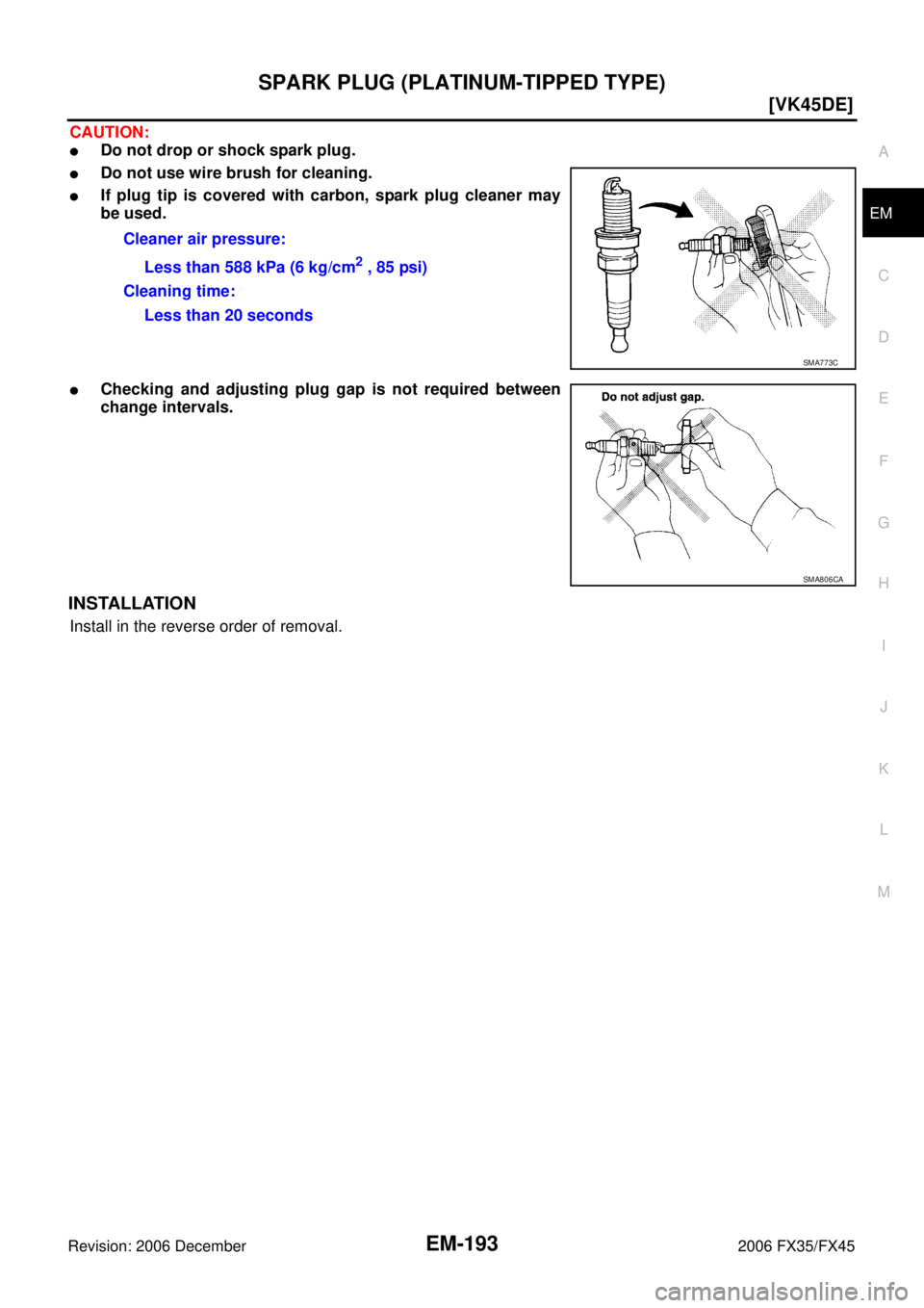
CAUTION:
�Do not drop or shock spark plug.
�Do not use wire brush for cleaning.
�If plug tip is covered with carbon, spark plug cleaner may
be used.
�Checking and adjusting plug gap is not required between
change intervals.
INSTALLATION
Install in the reverse order of removal. Cleaner air pressure:
Less than 588 kPa (6 kg/cm
2 , 85 psi)
Cleaning time: Less than 20 seconds
SMA773C
SMA806CA
Page 3026 of 4462
![INFINITI FX35 2006 Service Manual EM-232
[VK45DE]
CYLINDER HEAD
Revision: 2006 December 2006 FX35/FX45
CYLINDER HEADPFP:11041
On-Vehicle ServiceNBS003IJ
CHECKING COMPRESSION PRESSURE
1. Warm up engine thoroughly. Then, stop it.
2. Re](/manual-img/42/57019/w960_57019-3025.png "INFINITI FX35 2006 Service Manual EM-232
[VK45DE]
CYLINDER HEAD
Revision: 2006 December 2006 FX35/FX45
CYLINDER HEADPFP:11041
On-Vehicle ServiceNBS003IJ
CHECKING COMPRESSION PRESSURE
1. Warm up engine thoroughly. Then, stop it.
2. Re")
EM-232
[VK45DE]
CYLINDER HEAD
Revision: 2006 December 2006 FX35/FX45
CYLINDER HEADPFP:11041
On-Vehicle ServiceNBS003IJ
CHECKING COMPRESSION PRESSURE
1. Warm up engine thoroughly. Then, stop it.
2. Release fuel pressure. Refer to EC-746, "
FUEL PRESSURE RELEASE" .
a. Remove fuel pump fuse to avoid fuel injection during measure- ment.
3. Remove engine cover with power tool. Refer to EM-173, "
ENGINE ROOM COVER" .
4. Remove ignition coil and spark plug from each cylinder. Refer to EM-191, "
IGNITION COIL" and EM-192,
"SPARK PLUG (PLATINUM-TIPPED TYPE)" .
5. Connect engine tachometer (not required in use of CONSULT-II).
6. Install compression gauge with adapter (SST or commercial ser- vice tool) onto spark plug hole.
�Use compression gauge adapter (SST) which is required on
No. 7 and 8 cylinders.
�Use compression gauge adapter (if no SST is used) whose
picking up end inserted to spark plug hole is smaller than 20
mm (0.79 in) in diameter. Otherwise, it may be caught by cyl-
inder head during removal.
7. With accelerator pedal fully depressed, turn ignition switch to “START” for cranking. When the gauge pointer stabilizes, read the compression pressure and engine rpm. Perform these steps to check each cyl-
inder.
Compression pressure:
Unit: kPa (kg/cm2 , psi) /rpm
CAUTION:
Always use a fully changed battery to obtain the specified engine speed.
PBIB1482E
PBIC1554E
SBIA0533E
Standard Minimum Deferential limit between cylinders
1,320 (13.5, 191) / 300 1,130 (11.5, 164) / 300 98 (1.0, 14) / 300
Page 3027 of 4462
![INFINITI FX35 2006 Service Manual CYLINDER HEAD EM-233
[VK45DE]
C
D E
F
G H
I
J
K L
M A
EM
Revision: 2006 December 2006 FX35/FX45
�If the engine speed is out of specified range, check battery liquid for proper gravity. Che](/manual-img/42/57019/w960_57019-3026.png "INFINITI FX35 2006 Service Manual CYLINDER HEAD EM-233
[VK45DE]
C
D E
F
G H
I
J
K L
M A
EM
Revision: 2006 December 2006 FX35/FX45
�If the engine speed is out of specified range, check battery liquid for proper gravity. Che")
CYLINDER HEAD EM-233
[VK45DE]
C
D E
F
G H
I
J
K L
M A
EM
Revision: 2006 December 2006 FX35/FX45
�If the engine speed is out of specified range, check battery liquid for proper gravity. Check engine
speed again with normal battery gravity.
�If compression pressure is below minimum value, check valve clearances and parts associated with
combustion chamber (valve, valve seat, piston, piston ring, cylinder bore, cylinder head, cylinder head
gasket). After the checking, measure compression pressure again.
�If some cylinders have low compression pressure, pour small amount of engine oil into the spark plug
hole of the cylinder to re-check it for compression.
–If the added engine oil improves the compression, piston rings may be worn out or damaged. Check the
piston rings and replace if necessary.
–If the compression pressure remains at low level despite the addition of engine oil, valves may be mal-
functioning. Check valves for damage. Replace valve or valve seat accordingly.
�If two adjacent cylinders have respectively low compression pressure and their compression remains
low even after the addition of engine oil, cylinder head gaskets are leaking. In such a case, replace cyl-
inder head gaskets.
8. After inspection is completed, install removed parts in the reverse order of removal.
9. Start engine, and make sure that engine runs smoothly.
10. Perform trouble diagnosis. If DTC appears, erase it. Refer to EC-748, "
TROUBLE DIAGNOSIS" .
ComponentsNBS003IK
Removal and InstallationNBS003IL
REMOVAL
1. Remove engine assembly from vehicle. Refer to EM-243, "ENGINE ASSEMBLY" .
2. Remove exhaust manifold. Refer to EM-183, "
EXHAUST MANIFOLD AND THREE WAY CATALYST" .
3. Remove camshaft. Refer to EM-215, "
CAMSHAFT" .
1. Engine coolant temperature sensor 2. Washer 3. Cylinder head gasket (left bank)
4. Harness bracket 5. Cylinder head (right bank) 6. Cylinder head bolt
7. Cylinder head gasket (right bank) 8. Cylinder head bolt 9. Cylinder head (left bank)
PBIC2756E
Page 3030 of 4462
![INFINITI FX35 2006 Service Manual EM-236
[VK45DE]
CYLINDER HEAD
Revision: 2006 December 2006 FX35/FX45
Disassembly and AssemblyNBS003IM
COMPONENTS
DISASSEMBLY
1. Remove spark plug with spark plug wrench (commercial service tool).
2.](/manual-img/42/57019/w960_57019-3029.png "INFINITI FX35 2006 Service Manual EM-236
[VK45DE]
CYLINDER HEAD
Revision: 2006 December 2006 FX35/FX45
Disassembly and AssemblyNBS003IM
COMPONENTS
DISASSEMBLY
1. Remove spark plug with spark plug wrench (commercial service tool).
2.")
EM-236
[VK45DE]
CYLINDER HEAD
Revision: 2006 December 2006 FX35/FX45
Disassembly and AssemblyNBS003IM
COMPONENTS
DISASSEMBLY
1. Remove spark plug with spark plug wrench (commercial service tool).
2. Remove adjusting shim and valve lifter.
�Identify installation positions, and store them without mixing them up.
3. Remove valve collet.
�Compress valve spring with valve spring compressor, attach-
ment and adapter (SST). Remove valve collet with magnetic
hand.
CAUTION:
When working, take care not to damage valve lifter holes.
4. Remove valve spring retainer and valve spring (with valve spring seat). CAUTION:
Do not remove valve spring seat from valve spring.
5. Push valve stem to combustion chamber side, and remove valve.
1. Spark plug 2. Adjusting shim 3. Valve lifter
4. Valve collet 5. Valve spring retainer 6. Valve spring (with valve spring seat)
7. Valve oil seal 8. Valve guide 9. Valve seat
10. Valve (INT) 11. Valve (EXH) 12. Cylinder head (left bank)
13. Spark plug tube 14. Cylinder head (right bank)
PBIC2757E
PBIC2360E
![INFINITI FX35 2006 Service Manual PREPARATION EM-169
[VK45DE]
C
D E
F
G H
I
J
K L
M A
EM
Revision: 2006 December 2006 FX35/FX45
Commercial Service ToolsNBS003HJ
—
(J-45476)
Ring gear stopper Removing and installing cr](/manual-img/42/57019/w960_57019-2962.png "INFINITI FX35 2006 Service Manual PREPARATION EM-169
[VK45DE]
C
D E
F
G H
I
J
K L
M A
EM
Revision: 2006 December 2006 FX35/FX45
Commercial Service ToolsNBS003HJ
—
(J-45476)
Ring gear stopper Removing and installing cr")
![INFINITI FX35 2006 Service Manual IGNITION COIL EM-191
[VK45DE]
C
D E
F
G H
I
J
K L
M A
EM
Revision: 2006 December 2006 FX35/FX45
IGNITION COILPFP:22448
ComponentsNBS003I3
Removal and InstallationNBS003I4
REMOVAL
1. Remove](/manual-img/42/57019/w960_57019-2984.png "INFINITI FX35 2006 Service Manual IGNITION COIL EM-191
[VK45DE]
C
D E
F
G H
I
J
K L
M A
EM
Revision: 2006 December 2006 FX35/FX45
IGNITION COILPFP:22448
ComponentsNBS003I3
Removal and InstallationNBS003I4
REMOVAL
1. Remove")