2006 INFINITI FX35 wiring diagram
[x] Cancel search: wiring diagramPage 4107 of 4462
SC-1
STARTING & CHARGING SYSTEM
K ELECTRICAL
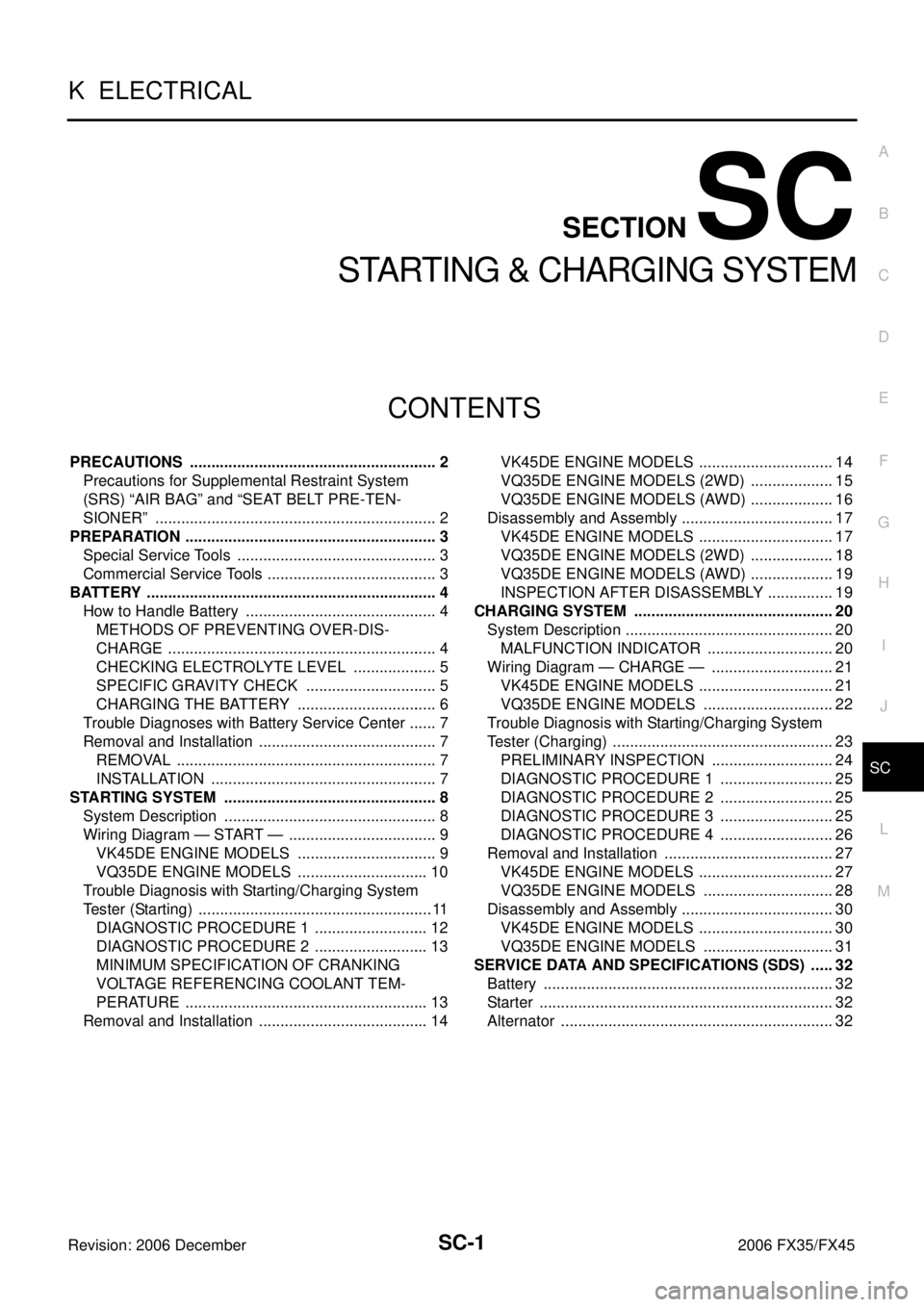
CONTENTS
C
D E
F
G H
I
J
L
M
SECTION SC
A
B
SC
Revision: 2006 December 2006 FX35/FX45
STARTING & CHARGING SYSTEM
PRECAUTIONS ..................................................... ..... 2
Precautions for Supplemental Restraint System
(SRS) “AIR BAG” and “SEAT BELT PRE-TEN-
SIONER” ............................................................. ..... 2
PREPARATION ...................................................... ..... 3
Special Service Tools .......................................... ..... 3
Commercial Service Tools ................................... ..... 3
BATTERY ............................................................... ..... 4
How to Handle Battery ........................................ ..... 4
METHODS OF PREVENTING OVER-DIS-
CHARGE .......................................................... ..... 4
CHECKING ELECTROLYTE LEVEL ............... ..... 5
SPECIFIC GRAVITY CHECK .......................... ..... 5
CHARGING THE BATTERY ............................ ..... 6
Trouble Diagnoses with Battery Service Center .. ..... 7
Removal and Installation ..................................... ..... 7
REMOVAL ........................................................ ..... 7
INSTALLATION ................................................ ..... 7
STARTING SYSTEM ............................................. ..... 8
System Description ............................................. ..... 8
Wiring Diagram — START — .............................. ..... 9
VK45DE ENGINE MODELS ............................ ..... 9
VQ35DE ENGINE MODELS ............................ ... 10
Trouble Diagnosis with Starting/Charging System
Tester (Starting) ................................................... .... 11
DIAGNOSTIC PROCEDURE 1 ........................ ... 12
DIAGNOSTIC PROCEDURE 2 ........................ ... 13
MINIMUM SPECIFICATION OF CRANKING
VOLTAGE REFERENCING COOLANT TEM-
PERATURE ...................................................... ... 13
Removal and Installation ..................................... ... 14 VK45DE ENGINE MODELS .............................
... 14
VQ35DE ENGINE MODELS (2WD) ................. ... 15
VQ35DE ENGINE MODELS (AWD) ................. ... 16
Disassembly and Assembly ................................. ... 17
VK45DE ENGINE MODELS ............................. ... 17
VQ35DE ENGINE MODELS (2WD) ................. ... 18
VQ35DE ENGINE MODELS (AWD) ................. ... 19
INSPECTION AFTER DISASSEMBLY ............. ... 19
CHARGING SYSTEM ............................................ ... 20
System Description .............................................. ... 20
MALFUNCTION INDICATOR ........................... ... 20
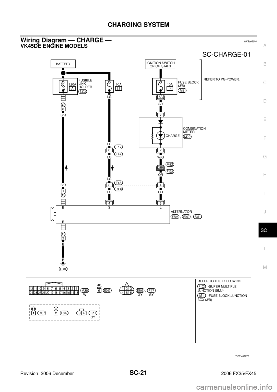
Wiring Diagram — CHARGE — .......................... ... 21
VK45DE ENGINE MODELS ............................. ... 21
VQ35DE ENGINE MODELS ............................ ... 22
Trouble Diagnosis with Starting/Charging System
Tester (Charging) ................................................. ... 23
PRELIMINARY INSPECTION .......................... ... 24
DIAGNOSTIC PROCEDURE 1 ........................ ... 25
DIAGNOSTIC PROCEDURE 2 ........................ ... 25
DIAGNOSTIC PROCEDURE 3 ........................ ... 25
DIAGNOSTIC PROCEDURE 4 ........................ ... 26
Removal and Installation ..................................... ... 27
VK45DE ENGINE MODELS ............................. ... 27
VQ35DE ENGINE MODELS ............................ ... 28
Disassembly and Assembly ................................. ... 30
VK45DE ENGINE MODELS ............................. ... 30
VQ35DE ENGINE MODELS ............................ ... 31
SERVICE DATA AND SPECIFICATIONS (SDS) ... ... 32
Battery ................................................................. ... 32
Starter .................................................................. ... 32
Alternator ............................................................. ... 32
Page 4115 of 4462

STARTING SYSTEM SC-9
C
D E
F
G H
I
J
L
M A
B
SC
Revision: 2006 December 2006 FX35/FX45
Wiring Diagram — START —NKS002UR
VK45DE ENGINE MODELS
TKWM1275E
Page 4127 of 4462
CHARGING SYSTEM SC-21
C
D E
F
G H
I
J
L
M A
B
SC
Revision: 2006 December 2006 FX35/FX45
Wiring Diagram — CHARGE —NKS002UW
VK45DE ENGINE MODELS
TKWM4287E
Page 4139 of 4462
SE-1
SEAT
I BODY
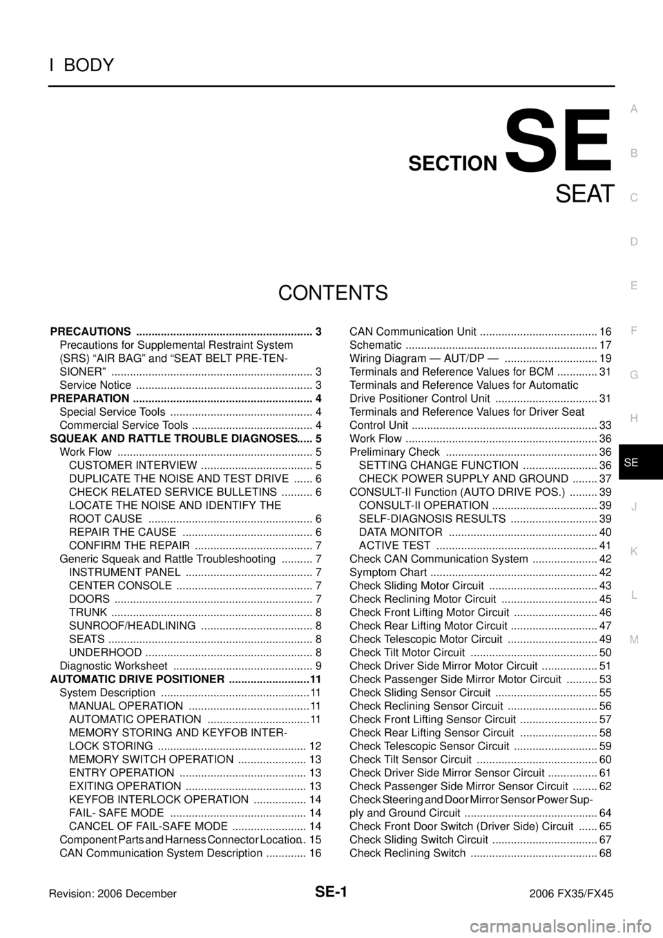
CONTENTS
C
D E
F
G H
J
K L
M
SECTION SE
A
B
SE
Revision: 2006 December 2006 FX35/FX45
SEAT
PRECAUTIONS ..................................................... ..... 3
Precautions for Supplemental Restraint System
(SRS) “AIR BAG” and “SEAT BELT PRE-TEN-
SIONER” ............................................................. ..... 3
Service Notice ..................................................... ..... 3
PREPARATION ...................................................... ..... 4
Special Service Tools .......................................... ..... 4
Commercial Service Tools ................................... ..... 4
SQUEAK AND RATTLE TROUBLE DIAGNOSES ..... 5
Work Flow ........................................................... ..... 5
CUSTOMER INTERVIEW ................................ ..... 5
DUPLICATE THE NOISE AND TEST DRIVE .. ..... 6
CHECK RELATED SERVICE BULLETINS ...... ..... 6
LOCATE THE NOISE AND IDENTIFY THE
ROOT CAUSE ................................................. ..... 6
REPAIR THE CAUSE ...................................... ..... 6
CONFIRM THE REPAIR .................................. ..... 7
Generic Squeak and Rattle Troubleshooting ...... ..... 7
INSTRUMENT PANEL ..................................... ..... 7
CENTER CONSOLE ........................................ ..... 7
DOORS ............................................................ ..... 7
TRUNK ............................................................. ..... 8
SUNROOF/HEADLINING ................................ ..... 8
SEATS .............................................................. ..... 8
UNDERHOOD .................................................. ..... 8
Diagnostic Worksheet ......................................... ..... 9
AUTOMATIC DRIVE POSITIONER ....................... ....11
System Description ............................................. .... 11
MANUAL OPERATION .................................... .... 11
AUTOMATIC OPERATION .............................. .... 11
MEMORY STORING AND KEYFOB INTER-
LOCK STORING .............................................. ... 12
MEMORY SWITCH OPERATION .................... ... 13
ENTRY OPERATION ....................................... ... 13
EXITING OPERATION ..................................... ... 13
KEYFOB INTERLOCK OPERATION ............... ... 14
FAIL- SAFE MODE .......................................... ... 14
CANCEL OF FAIL-SAFE MODE ...................... ... 14
Component Parts and Harness Connector Location ... 15
CAN Communication System Description ........... ... 16 CAN Communication Unit ....................................
... 16
Schematic ............................................................ ... 17
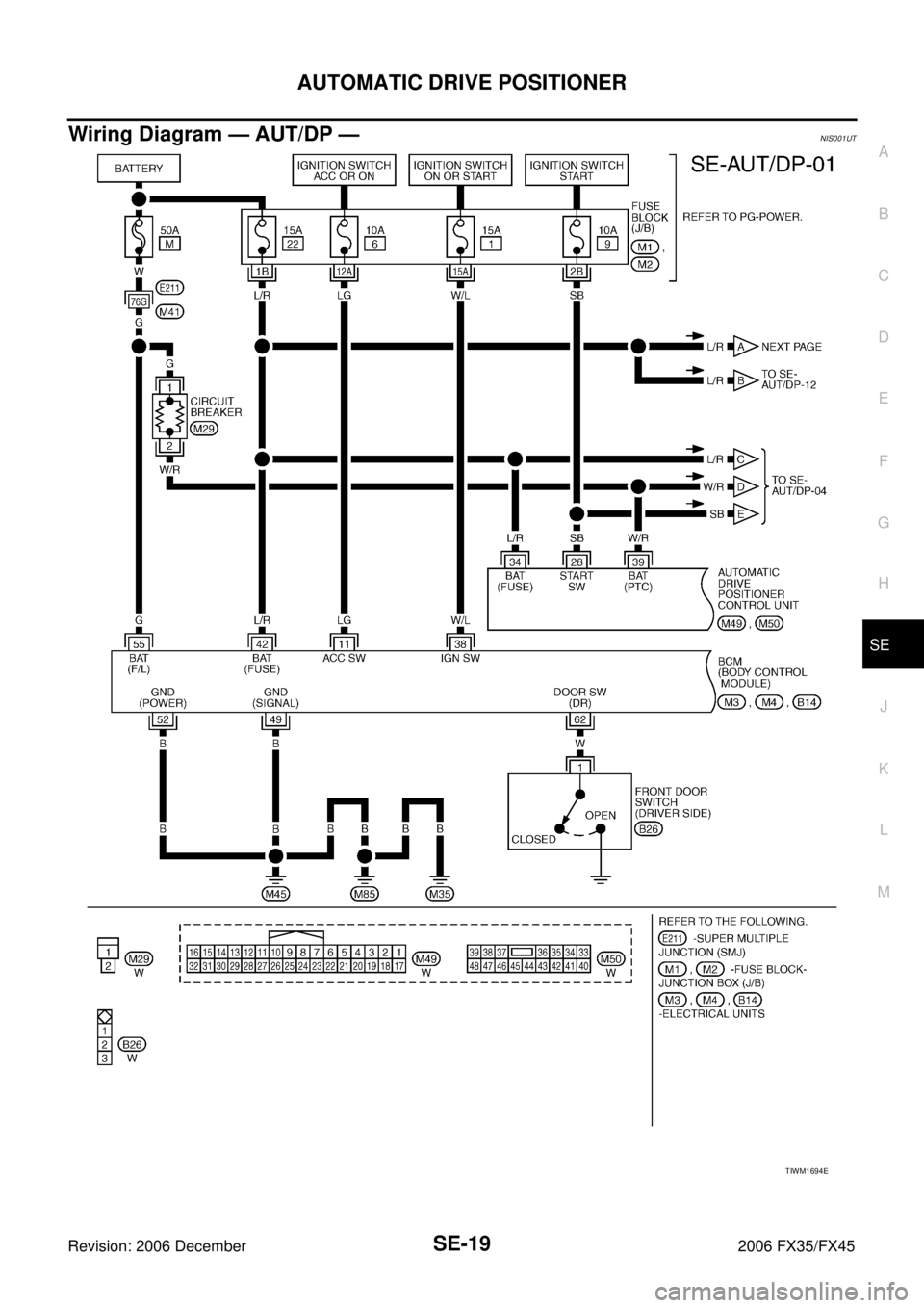
Wiring Diagram — AUT/DP — ............................ ... 19
Terminals and Reference Values for BCM ........... ... 31
Terminals and Reference Values for Automatic
Drive Positioner Control Unit ............................... ... 31
Terminals and Reference Values for Driver Seat
Control Unit .......................................................... ... 33
Work Flow ............................................................ ... 36
Preliminary Check ............................................... ... 36
SETTING CHANGE FUNCTION ...................... ... 36
CHECK POWER SUPPLY AND GROUND ...... ... 37
CONSULT-II Function (AUTO DRIVE POS.) ....... ... 39
CONSULT-II OPERATION ................................ ... 39
SELF-DIAGNOSIS RESULTS .......................... ... 39
DATA MONITOR .............................................. ... 40
ACTIVE TEST .................................................. ... 41
Check CAN Communication System ................... ... 42
Symptom Chart .................................................... ... 42
Check Sliding Motor Circuit ................................. ... 43
Check Reclining Motor Circuit ............................. ... 45
Check Front Lifting Motor Circuit ......................... ... 46
Check Rear Lifting Motor Circuit .......................... ... 47
Check Telescopic Motor Circuit ........................... ... 49
Check Tilt Motor Circuit ....................................... ... 50
Check Driver Side Mirror Motor Circuit ................ ... 51
Check Passenger Side Mirror Motor Circuit ........ ... 53
Check Sliding Sensor Circuit ............................... ... 55
Check Reclining Sensor Circuit ........................... ... 56
Check Front Lifting Sensor Circuit ....................... ... 57
Check Rear Lifting Sensor Circuit ....................... ... 58
Check Telescopic Sensor Circuit ......................... ... 59
Check Tilt Sensor Circuit ..................................... ... 60
Check Driver Side Mirror Sensor Circuit .............. ... 61
Check Passenger Side Mirror Sensor Circuit ...... ... 62
Check Steering and Door Mirror Sensor Power Sup-
ply and Ground Circuit ......................................... ... 64
Check Front Door Switch (Driver Side) Circuit .... ... 65
Check Sliding Switch Circuit ................................ ... 67
Check Reclining Switch ....................................... ... 68
Page 4140 of 4462

SE-2Revision: 2006 December 2006 FX35/FX45 Check Front Lifting Switch Circuit ........................
... 70
Check Rear Lifting Switch Circuit ........................ ... 71
Check Power Seat Switch Ground Circuit ........... ... 72
Check Telescopic Switch Circuit .......................... ... 73
Check Tilt Switch Circuit ...................................... ... 75
Check Door Mirror Remote Control Switch
(Changeover Switch) Circuit ................................ ... 77
Check Door Mirror Remote Control Switch (Mirror
Switch) Circuit ...................................................... ... 79
Check Detention Switch (P Range Switch) Circuit ... 81
Check Key Switch Circuit (With Intelligent Key) .. ... 82
Check Key Switch Circuit (Without Intelligent Key) ... 84
Check Seat Memory Switch Circuit ..................... ... 85
Check Seat Memory Indicator Lamp Circuit ........ ... 87
Check UART Communication Line Circuit ........... ... 88
Check Lumbar Support Circuit ............................ ... 90
POWER SEAT ........................................................ ... 92
Wiring Diagram — SEAT — ................................. ... 92
HEATED SEAT ....................................................... ... 94
Description ........................................................... ... 94
Wiring Diagram — HSEAT — .............................. ... 95 FRONT SEAT .........................................................
... 97
Removal and Installation ...................................... ... 97
REMOVAL ......................................................... .100
INSTALLATION ................................................. .102
REMOVAL OF SEATBACK TRIM AND PAD .... .102
INSTALLATION OF SEATBACK TRIM AND PAD .103
REMOVAL OF SEAT CUSHION TRIM AND PAD .103
INSTALLATION OF SEAT CUSHION TRIM AND
PAD ................................................................... .104
REAR SEAT ............................................................ .105
Removal and Installation ...................................... .105
REMOVAL ......................................................... .107
INSTALLATION ................................................. .107
REMOVAL OF SEAT CUSHION TRIM AND PAD .107
INSTALLATION OF SEAT CUSHION TRIM AND
PAD ................................................................... .108
REMOVAL OF SEATBACK TRIM AND PAD .... .108
INSTALLATION OF SEATBACK TRIM AND PAD .108
REMOVAL OF REMOTE CONTROL LEVER ... .109
INSTALLATION OF REMOTE CONTROL
LEVER .............................................................. .109
Page 4157 of 4462
AUTOMATIC DRIVE POSITIONER SE-19
C
D E
F
G H
J
K L
M A
B
SE
Revision: 2006 December 2006 FX35/FX45
Wiring Diagram — AUT/DP —NIS001UT
TIWM1694E
Page 4230 of 4462
SE-92
POWER SEAT
Revision: 2006 December 2006 FX35/FX45
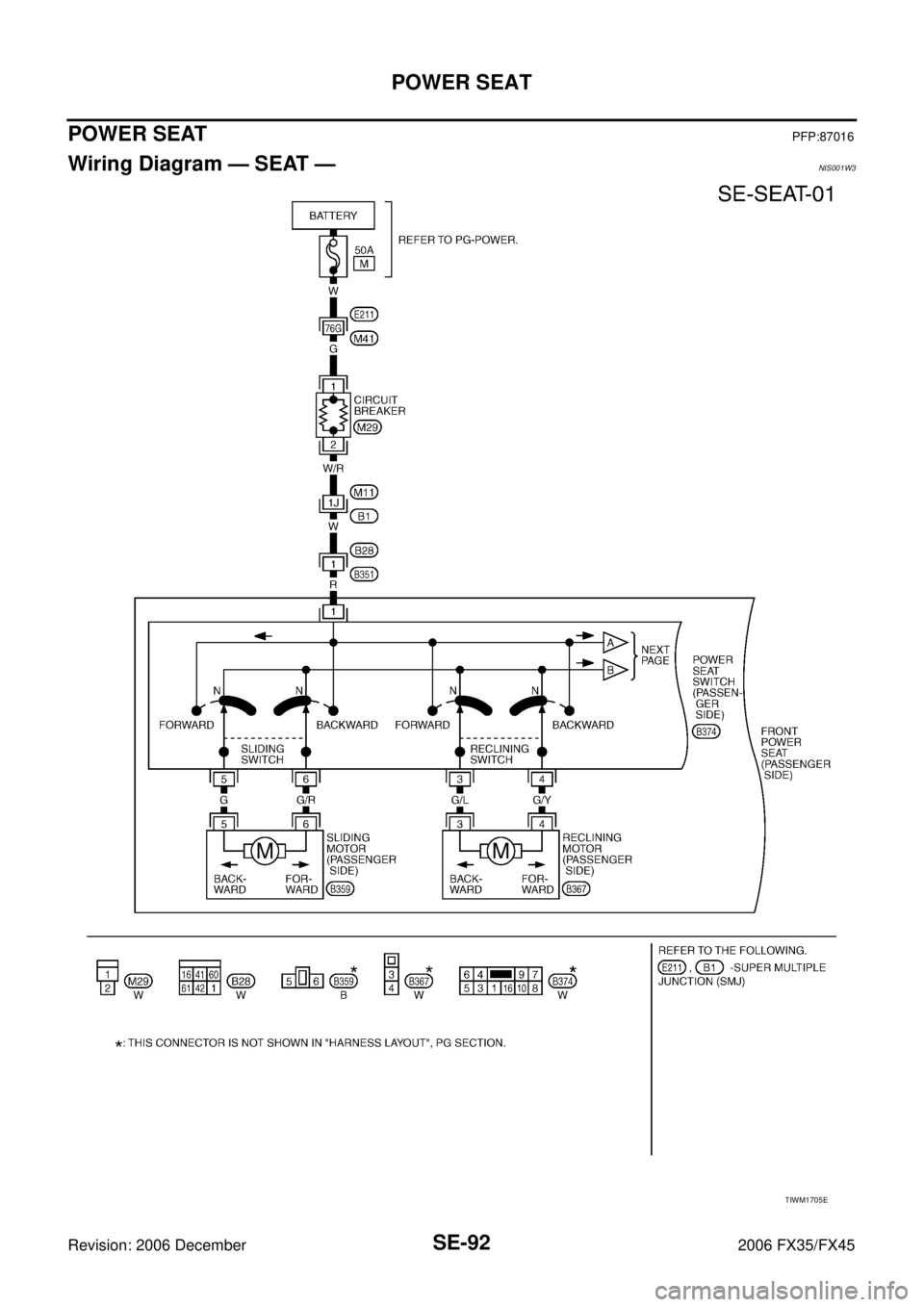
POWER SEATPFP:87016
Wiring Diagram — SEAT —NIS001W3
TIWM1705E
Page 4233 of 4462
HEATED SEAT SE-95
C
D E
F
G H
J
K L
M A
B
SE
Revision: 2006 December 2006 FX35/FX45
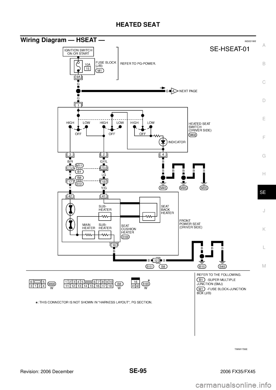
Wiring Diagram — HSEAT —NIS001W6
TIWM1706E