2006 INFINITI FX35 ignition
[x] Cancel search: ignitionPage 1377 of 4462
REAR VIEW MONITOR DI-127
C
D E
F
G H
I
J
L
M A
B
DI
Revision: 2006 December 2006 FX35/FX45
Rear View Is Not Displayed With The A/T Selector Lever In R-PositionNKS00321
1. BACK-UP LAMP INSPECTION
1. Turn ignition switch ON.
2. Shift A/T selector lever to R position.
Does back-up lamp illuminate?
YES >> GO TO 2.
NO >> Check back-up lamp system. Refer to LT- 1 3 1 , "
BACK-UP LAMP" in LT section.
2. CHECK REVERSE POSITION INPUT SIGNAL
With CONSULT-II
1. Select “DATA MONITOR” of “REARVIEW CAMERA”.
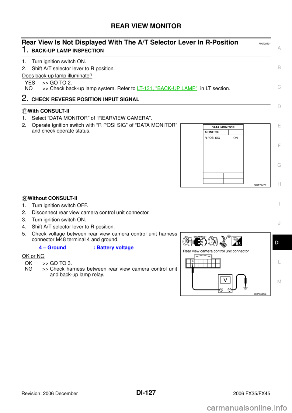
2. Operate ignition switch with “R POSI SIG” of “DATA MONITOR” and check operate status.
Without CONSULT-II
1. Turn ignition switch OFF.
2. Disconnect rear view camera control unit connector.
3. Turn ignition switch ON.
4. Shift A/T selector lever to R position.
5. Check voltage between rear view camera control unit harness connector M48 terminal 4 and ground.
OK or NG
OK >> GO TO 3.
NG >> Check harness between rear view camera control unit
and back-up lamp relay.
SKIA7147E
4 – Ground : Battery voltage
SKIA5086E
Page 1378 of 4462
DI-128
REAR VIEW MONITOR
Revision: 2006 December 2006 FX35/FX45
3. CHECK DISPLAY CONTROL UNIT OUTPUT SIGNAL
1. Turn ignition switch OFF.
2. Disconnect rear view camera control unit connector.
3. Turn ignition switch ON.
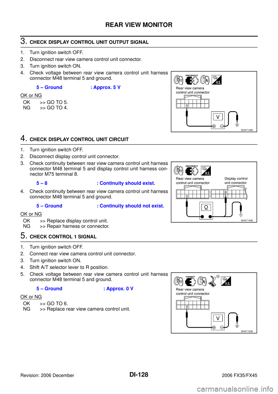
4. Check voltage between rear view camera control unit harness connector M48 terminal 5 and ground.
OK or NG
OK >> GO TO 5.
NG >> GO TO 4.
4. CHECK DISPLAY CONTROL UNIT CIRCUIT
1. Turn ignition switch OFF.
2. Disconnect display control unit connector.
3. Check continuity between rear view camera control unit harness connector M48 terminal 5 and display control unit harness con-
nector M75 terminal 8.
4. Check continuity between rear view camera control unit harness connector M48 terminal 5 and ground.
OK or NG
OK >> Replace display control unit.
NG >> Repair harness or connector.
5. CHECK CONTROL 1 SIGNAL
1. Turn ignition switch OFF.
2. Connect rear view camera control unit connector.
3. Turn ignition switch ON.
4. Shift A/T selector lever to R position.
5. Check voltage between rear view camera control unit harness connector M48 terminal 5 and ground.
OK or NG
OK >> GO TO 6.
NG >> Replace rear view camera control unit. 5 – Ground : Approx. 5 V
SKIA7148E
5 – 8 : Continuity should exist.
5 – Ground : Continuity should not exist.
SKIA7149E
5 – Ground : Approx. 0 V
SKIA7150E
Page 1379 of 4462
REAR VIEW MONITOR DI-129
C
D E
F
G H
I
J
L
M A
B
DI
Revision: 2006 December 2006 FX35/FX45
6. CHECK REAR VIEW CAMERA OPEN CIRCUIT
1. Turn ignition switch OFF.
2. Disconnect rear view camera connector.
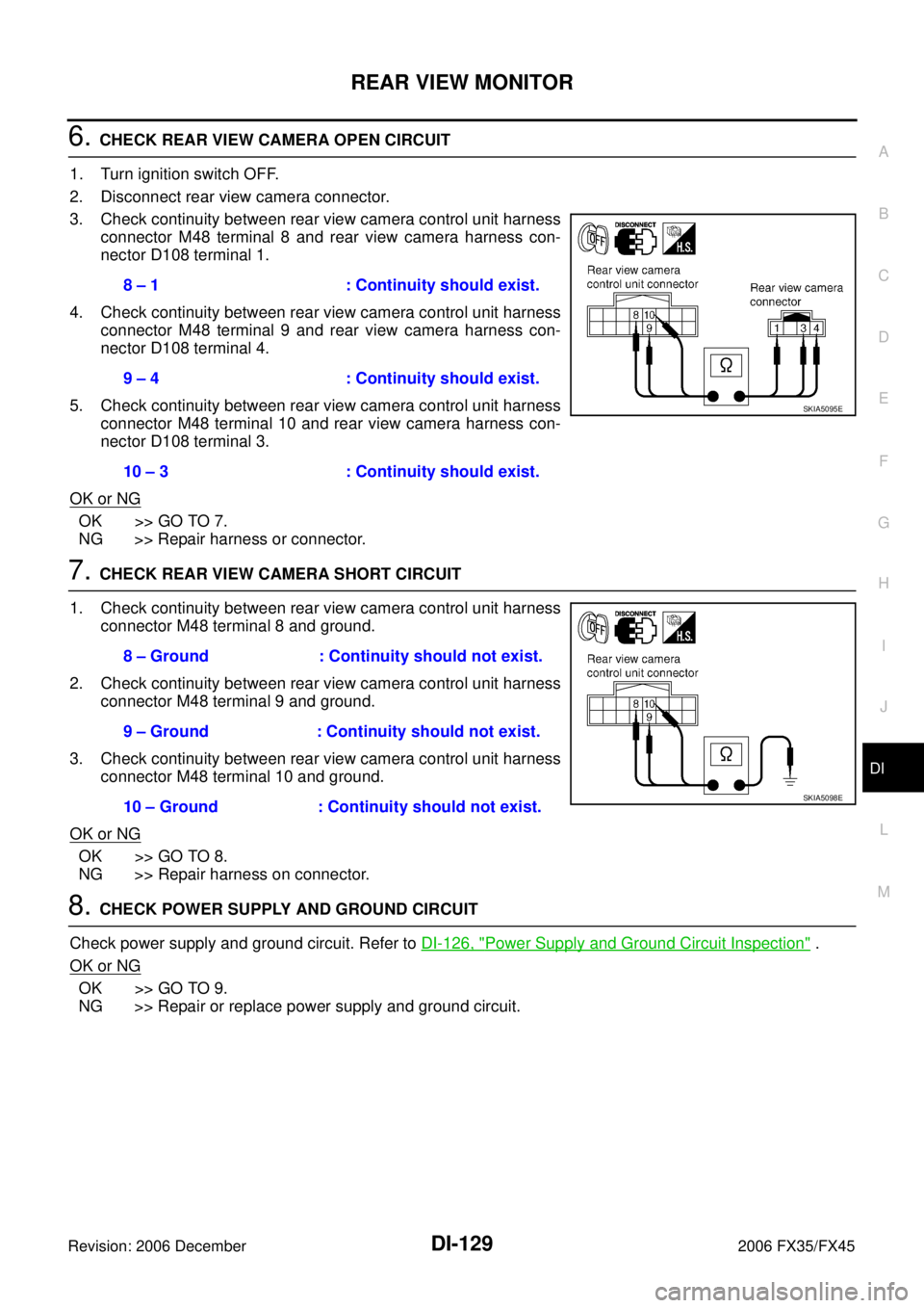
3. Check continuity between rear view camera control unit harness connector M48 terminal 8 and rear view camera harness con-
nector D108 terminal 1.
4. Check continuity between rear view camera control unit harness connector M48 terminal 9 and rear view camera harness con-
nector D108 terminal 4.
5. Check continuity between rear view camera control unit harness connector M48 terminal 10 and rear view camera harness con-
nector D108 terminal 3.
OK or NG
OK >> GO TO 7.
NG >> Repair harness or connector.
7. CHECK REAR VIEW CAMERA SHORT CIRCUIT
1. Check continuity between rear view camera control unit harness connector M48 terminal 8 and ground.
2. Check continuity between rear view camera control unit harness connector M48 terminal 9 and ground.
3. Check continuity between rear view camera control unit harness connector M48 terminal 10 and ground.
OK or NG
OK >> GO TO 8.
NG >> Repair harness on connector.
8. CHECK POWER SUPPLY AND GROUND CIRCUIT
Check power supply and ground circuit. Refer to DI-126, "
Power Supply and Ground Circuit Inspection" .
OK or NG
OK >> GO TO 9.
NG >> Repair or replace power supply and ground circuit. 8 – 1 : Continuity should exist.
9 – 4 : Continuity should exist.
10 – 3 : Continuity should exist.
SKIA5095E
8 – Ground : Continuity should not exist.
9 – Ground : Continuity should not exist.
10 – Ground : Continuity should not exist.
SKIA5098E
Page 1380 of 4462
DI-130
REAR VIEW MONITOR
Revision: 2006 December 2006 FX35/FX45
9. CHECK REAR VIEW CAMERA CONTROL UNIT OUTPUT SIGNAL
1. Turn ignition switch OFF.
2. Connect rear view camera control unit connector.
3. Turn ignition switch ON.
4. Shift A/T selector lever to R position.
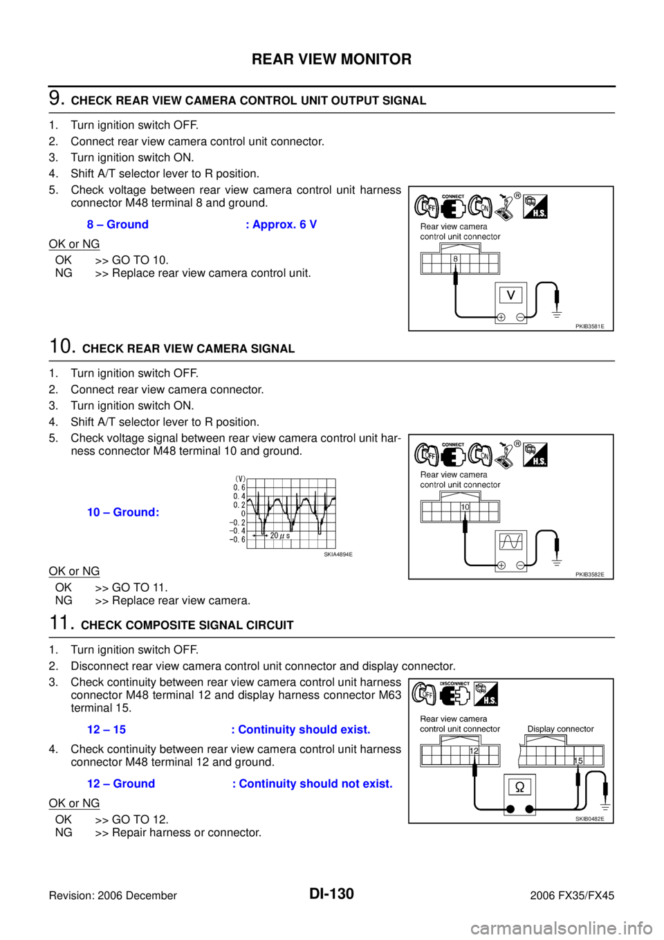
5. Check voltage between rear view camera control unit harness connector M48 terminal 8 and ground.
OK or NG
OK >> GO TO 10.
NG >> Replace rear view camera control unit.
10. CHECK REAR VIEW CAMERA SIGNAL
1. Turn ignition switch OFF.
2. Connect rear view camera connector.
3. Turn ignition switch ON.
4. Shift A/T selector lever to R position.
5. Check voltage signal between rear view camera control unit har- ness connector M48 terminal 10 and ground.
OK or NG
OK >> GO TO 11.
NG >> Replace rear view camera.
11 . CHECK COMPOSITE SIGNAL CIRCUIT
1. Turn ignition switch OFF.
2. Disconnect rear view camera control unit connector and display connector.
3. Check continuity between rear view camera control unit harness connector M48 terminal 12 and display harness connector M63
terminal 15.
4. Check continuity between rear view camera control unit harness connector M48 terminal 12 and ground.
OK or NG
OK >> GO TO 12.
NG >> Repair harness or connector. 8 – Ground : Approx. 6 V
PKIB3581E
10 – Ground:
PKIB3582E
SKIA4894E
12 – 15 : Continuity should exist.
12 – Ground : Continuity should not exist.
SKIB0482E
Page 1381 of 4462
REAR VIEW MONITOR DI-131
C
D E
F
G H
I
J
L
M A
B
DI
Revision: 2006 December 2006 FX35/FX45
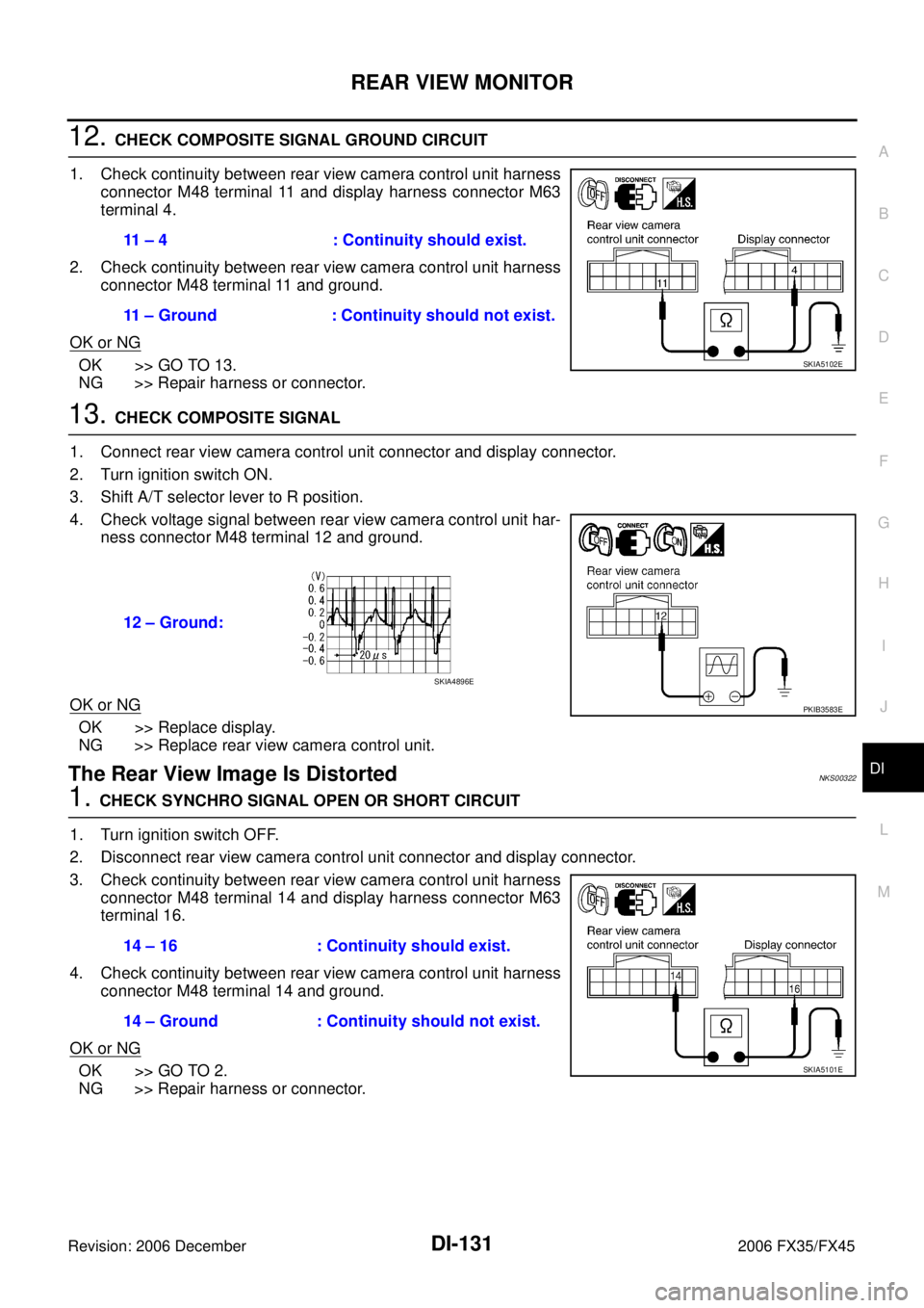
12. CHECK COMPOSITE SIGNAL GROUND CIRCUIT
1. Check continuity between rear view camera control unit harness connector M48 terminal 11 and display harness connector M63
terminal 4.
2. Check continuity between rear view camera control unit harness connector M48 terminal 11 and ground.
OK or NG
OK >> GO TO 13.
NG >> Repair harness or connector.
13. CHECK COMPOSITE SIGNAL
1. Connect rear view camera control unit connector and display connector.
2. Turn ignition switch ON.
3. Shift A/T selector lever to R position.
4. Check voltage signal between rear view camera control unit har- ness connector M48 terminal 12 and ground.
OK or NG
OK >> Replace display.
NG >> Replace rear view camera control unit.
The Rear View Image Is DistortedNKS00322
1. CHECK SYNCHRO SIGNAL OPEN OR SHORT CIRCUIT
1. Turn ignition switch OFF.
2. Disconnect rear view camera control unit connector and display connector.
3. Check continuity between rear view camera control unit harness connector M48 terminal 14 and display harness connector M63
terminal 16.
4. Check continuity between rear view camera control unit harness connector M48 terminal 14 and ground.
OK or NG
OK >> GO TO 2.
NG >> Repair harness or connector. 11 – 4 : Continuity should exist.
11 – Ground : Continuity should not exist.
SKIA5102E
12 – Ground:
PKIB3583E
SKIA4896E
14 – 16 : Continuity should exist.
14 – Ground : Continuity should not exist.
SKIA5101E
Page 1382 of 4462
DI-132
REAR VIEW MONITOR
Revision: 2006 December 2006 FX35/FX45
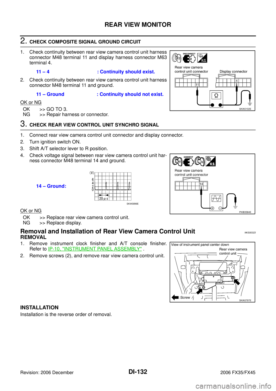
2. CHECK COMPOSITE SIGNAL GROUND CIRCUIT
1. Check continuity between rear view camera control unit harness connector M48 terminal 11 and display harness connector M63
terminal 4.
2. Check continuity between rear view camera control unit harness connector M48 terminal 11 and ground.
OK or NG
OK >> GO TO 3.
NG >> Repair harness or connector.
3. CHECK REAR VIEW CONTROL UNIT SYNCHRO SIGNAL
1. Connect rear view camera control unit connector and display connector.
2. Turn ignition switch ON.
3. Shift A/T selector lever to R position.
4. Check voltage signal between rear view camera control unit har- ness connector M48 terminal 14 and ground.
OK or NG
OK >> Replace rear view camera control unit.
NG >> Replace display.
Removal and Installation of Rear View Camera Control UnitNKS00323
REMOVAL
1. Remove instrument clock finisher and A/T console finisher. Refer to IP-10, "
INSTRUMENT PANEL ASSEMBLY" .
2. Remove screws (2), and remove rear view camera control unit.
INSTALLATION
Installation is the reverse order of removal. 11 – 4 : Continuity should exist.
11 – Ground : Continuity should not exist.
SKIA5102E
14 – Ground:
PKIB3584E
SKIA5896E
SKIA5797E
Page 1385 of 4462
EC-1
ENGINE CONTROL SYSTEM
B ENGINE
CONTENTS
C
D E
F
G H
I
J
K L
M
SECTION EC
A
EC
Revision: 2006 December 2006 FX35/FX45
ENGINE CONTROL SYSTEM
VQ35DE
INDEX FOR DTC ................................................... ... 15
DTC No. Index .................................................... ... 15
Alphabetical Index ............................................... ... 19
PRECAUTIONS ..................................................... ... 23
Precautions for Supplemental Restraint System
(SRS) “AIR BAG” and “SEAT BELT PRE-TEN-
SIONER” ............................................................. ... 23
On Board Diagnostic (OBD) System of Engine and
A/T ....................................................................... ... 23
Precaution ........................................................... ... 23
PREPARATION ...................................................... ... 27
Special Service Tools .......................................... ... 27
Commercial Service Tools ................................... ... 29
ENGINE CONTROL SYSTEM ............................... ... 30
System Diagram .................................................. ... 30
Multiport Fuel Injection (MFI) System ................. ... 31
Electronic Ignition (EI) System ............................ ... 33
Fuel Cut Control (at No Load and High Engine
Speed) ................................................................. ... 34
AIR CONDITIONING CUT CONTROL .................. ... 35
Input/Output Signal Chart .................................... ... 35
System Description ............................................. ... 35
AUTOMATIC SPEED CONTROL DEVICE (ASCD) ... 36
System Description ............................................. ... 36
Component Description ....................................... ... 37
CAN COMMUNICATION ....................................... ... 38
System Description ............................................. ... 38
EVAPORATIVE EMISSION SYSTEM .................... ... 39
Description .......................................................... ... 39
Component Inspection ........................................ ... 42
Removal and Installation ..................................... ... 43
How to Detect Fuel Vapor Leakage .................... ... 43
ON BOARD REFUELING VAPOR RECOVERY
(ORVR) ................................................................... ... 46
System Description ............................................. ... 46
Diagnostic Procedure .......................................... ... 47
Component Inspection ........................................ ... 49 POSITIVE CRANKCASE VENTILATION ..............
... 51
Description ........................................................... ... 51
Component Inspection ......................................... ... 51
IVIS (INFINITI VEHICLE IMMOBILIZER SYSTEM-
NATS) ..................................................................... ... 53
Description ........................................................... ... 53
ON BOARD DIAGNOSTIC (OBD) SYSTEM ......... ... 54
Introduction .......................................................... ... 54
Two Trip Detection Logic ..................................... ... 54
Emission-Related Diagnostic Information ............ ... 55
Malfunction Indicator Lamp (MIL) ........................ ... 68
OBD System Operation Chart ............................. ... 72
BASIC SERVICE PROCEDURE ............................ ... 77
Basic Inspection .................................................. ... 77
Idle Speed and Ignition Timing Check ................. ... 82
VIN Registration .................................................. ... 83
Accelerator Pedal Released Position Learning ... ... 84
Throttle Valve Closed Position Learning .............. ... 84
Idle Air Volume Learning ..................................... ... 84
Fuel Pressure Check ........................................... ... 86
TROUBLE DIAGNOSIS ......................................... ... 88
Trouble Diagnosis Introduction ............................ ... 88
DTC Inspection Priority Chart .............................. ... 94
Fail-Safe Chart .................................................... ... 96
Symptom Matrix Chart ......................................... ... 97
Engine Control Component Parts Location ......... .101
Vacuum Hose Drawing ........................................ .107
Circuit Diagram .................................................... .108
ECM Harness Connector Terminal Layout .......... .110
ECM Terminals and Reference Value .................. .110
CONSULT-II Function (ENGINE) ......................... .119
Generic Scan Tool (GST) Function ...................... .130
CONSULT-II Reference Value in Data Monitor .... .133
Major Sensor Reference Graph in Data Monitor
Mode .................................................................... .136
TROUBLE DIAGNOSIS - SPECIFICATION VALUE .138
Description ........................................................... .138
Testing Condition ................................................. .138
Inspection Procedure ........................................... .138
Diagnostic Procedure .......................................... .139
Page 1391 of 4462
EC-7
C
D E
F
G H
I
J
K L
M
EC A
Revision: 2006 December 2006 FX35/FX45 CONSULT-II Reference Value in Data Monitor Mode
. 589
On Board Diagnosis Logic .................................. . 589
DTC Confirmation Procedure .............................. . 590
Wiring Diagram ................................................... . 591
Diagnostic Procedure .......................................... . 592
Component Inspection ........................................ . 595
Removal and Installation ..................................... . 595
DTC P2138 APP SENSOR .................................... . 596
Component Description ....................................... . 596
CONSULT-II Reference Value in Data Monitor Mode . 596
On Board Diagnosis Logic .................................. . 596
DTC Confirmation Procedure .............................. . 597
Wiring Diagram ................................................... . 598
Diagnostic Procedure .......................................... . 599
Component Inspection ........................................ . 603
Removal and Installation ..................................... . 603
DTC P2A00, P2A03 A/F SENSOR 1 ..................... . 604
Component Description ....................................... . 604
CONSULT-II Reference Value in Data Monitor Mode . 604
On Board Diagnosis Logic .................................. . 604
DTC Confirmation Procedure .............................. . 605
Wiring Diagram ................................................... . 606
Diagnostic Procedure .......................................... . 609
Removal and Installation ..................................... . 615
ASCD BRAKE SWITCH ........................................ . 616
Component Description ....................................... . 616
CONSULT-II Reference Value in Data Monitor Mode . 616
Wiring Diagram ................................................... . 617
Diagnostic Procedure .......................................... . 618
Component Inspection ........................................ . 622
ASCD INDICATOR ................................................ . 623
Component Description ....................................... . 623
CONSULT-II Reference Value in Data Monitor Mode . 623
Wiring Diagram ................................................... . 624
Diagnostic Procedure .......................................... . 625
ELECTRICAL LOAD SIGNAL ............................... . 626
Description .......................................................... . 626
CONSULT-II Reference Value in Data Monitor Mode . 626
Diagnostic Procedure .......................................... . 626
FUEL INJECTOR ................................................... . 628
Component Description ....................................... . 628
CONSULT-II Reference Value in Data Monitor Mode . 628
Wiring Diagram ................................................... . 629
Diagnostic Procedure .......................................... . 630
Component Inspection ........................................ . 634
Removal and Installation ..................................... . 634
FUEL PUMP .......................................................... . 635
Description .......................................................... . 635
CONSULT-II Reference Value in Data Monitor Mode . 635
Wiring Diagram ................................................... . 636 Diagnostic Procedure ..........................................
.637
Component Inspection ......................................... .640
Removal and Installation ..................................... .640
ICC BRAKE SWITCH ............................................ .641
Component Description ....................................... .641
CONSULT-II Reference Value in Data Monitor Mode .641
Wiring Diagram .................................................... .642
Diagnostic Procedure .......................................... .643
Component Inspection ......................................... .648
IGNITION SIGNAL ................................................. .649
Component Description ....................................... .649
Wiring Diagram .................................................... .650
Diagnostic Procedure .......................................... .655
Component Inspection ......................................... .660
Removal and Installation ..................................... .661
REFRIGERANT PRESSURE SENSOR ................. .662
Component Description ....................................... .662
Wiring Diagram .................................................... .663
Diagnostic Procedure .......................................... .664
Removal and Installation ..................................... .666
SNOW MODE SWITCH ......................................... .667
Description ........................................................... .667
CONSULT-II Reference Value in the Data Monitor
Mode .................................................................... .667
Wiring Diagram .................................................... .668
Diagnostic Procedure .......................................... .669
Component Inspection ......................................... .671
MIL AND DATA LINK CONNECTOR ..................... .672
Wiring Diagram .................................................... .672
SERVICE DATA AND SPECIFICATIONS (SDS) ... .674
Fuel Pressure ...................................................... .674
Idle Speed and Ignition Timing ............................ .674
Calculated Load Value ......................................... .674
Mass Air Flow Sensor .......................................... .674
Intake Air Temperature Sensor ............................ .674
Engine Coolant Temperature Sensor .................. .674
Air Fuel Ratio (A/F) Sensor 1 Heater ................... .674
Heated Oxygen sensor 2 Heater ......................... .674
Crankshaft Position Sensor (POS) ...................... .674
Camshaft Position Sensor (PHASE) ................... .674
Throttle Control Motor .......................................... .674
Fuel Injector ......................................................... .675
Fuel Pump ........................................................... .675
VK45DE
INDEX FOR DTC .................................................... .676
DTC No. Index ..................................................... .676
Alphabetical Index ............................................... .680
PRECAUTIONS ..................................................... .684
Precautions for Supplemental Restraint System
(SRS) “AIR BAG” and “SEAT BELT PRE-TEN-
SIONER” .............................................................. .684
Precautions for Procedures without Cowl Top Cover .684
On Board Diagnostic (OBD) System of Engine and
A/T ....................................................................... .684
Precaution ........................................................... .685