Page 2755 of 4462

SQUEAK AND RATTLE TROUBLE DIAGNOSES EI-7
C
D E
F
G H
J
K L
M A
B
EI
Revision: 2006 December 2006 FX35/FX45
INSULATOR (Light foam block)
80845-71L00: 30 mm (1.18 in) thick, 30 × 50 mm (1.18 × 1.97 in)
FELT CLOTHTAPE
Used to insulate where movement does not occur. Ideal for instrument panel applications.
68370-4B000: 15 × 25 mm (0.59 × 0.98 in) pad/68239-13E00: 5 mm (0.20 in) wide tape roll The following
materials, not found in the kit, can also be used to repair squeaks and rattles.
UHMW(TEFLON) TAPE
Insulates where slight movement is present. Ideal for instrument panel applications.
SILICONE GREASE
Used in place of UHMW tape that will be visible or not fit.
Note: Will only last a few months.
SILICONE SPRAY
Use when grease cannot be applied.
DUCT TAPE
Use to eliminate movement.
CONFIRM THE REPAIR
Confirm that the cause of a noise is repaired by test driving the vehicle. Operate the vehicle under the same
conditions as when the noise originally occurred. Refer to the notes on the Diagnostic Worksheet.
Generic Squeak and Rattle TroubleshootingNIS001TL
Refer to Table of Contents for specific component removal and installation information.
INSTRUMENT PANEL
Most incidents are caused by contact and movement between:
1. The cluster lid A and instrument panel
2. Acrylic lens and combination meter housing
3. Instrument panel to front pillar garnish
4. Instrument panel to windshield
5. Instrument panel mounting pins
6. Wiring harnesses behind the combination meter
7. A/C defroster duct and duct joint
These incidents can usually be located by tapping or moving the components to duplicate the noise or by
pressing on the components while driving to stop the noise. Most of these incidents can be repaired by apply-
ing felt cloth tape or silicon spray (in hard to reach areas). Urethane pads can be used to insulate wiring har-
ness.
CAUTION:
Do not use silicone spray to isolate a squeak or rattle. If you saturate the area with silicone, you will
not be able to recheck the repair.
CENTER CONSOLE
Components to pay attention to include:
1. Shifter assembly cover to finisher
2. A/C control unit and cluster lid C
3. Wiring harnesses behind audio and A/C control unit
The instrument panel repair and isolation procedures also apply to the center console.
DOORS
Pay attention to the:
1. Finisher and inner panel making a slapping noise
2. Inside handle escutcheon to door finisher
3. Wiring harnesses tapping
4. Door striker out of alignment causing a popping noise on starts and stops
Tapping or moving the components or pressing on them while driving to duplicate the conditions can isolate
many of these incidents. You can usually insulate the areas with felt cloth tape or insulator foam blocks from
the Nissan Squeak and Rattle Kit (J-43980) to repair the noise.
Page 2762 of 4462
EI-14
FRONT BUMPER
Revision: 2006 December 2006 FX35/FX45
FRONT BUMPERPFP:F2022
Removal and InstallationNIS001TO
PIIA4330E
Page 2763 of 4462

FRONT BUMPER EI-15
C
D E
F
G H
J
K L
M A
B
EI
Revision: 2006 December 2006 FX35/FX45
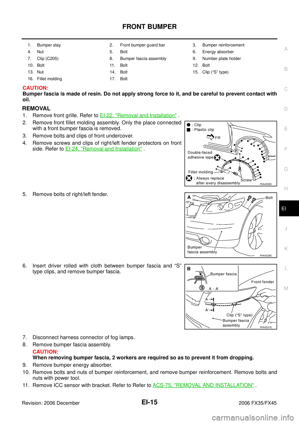
CAUTION:
Bumper fascia is made of resin. Do not apply strong force to it, and be careful to prevent contact with
oil.
REMOVAL
1. Remove front grille. Refer to EI-22, "Removal and Installation" .
2. Remove front fillet molding assembly. Only the place connected with a front bumper fascia is removed.
3. Remove bolts and clips of front undercover.
4. Remove screws and clips of right/left fender protectors on front side. Refer to EI-24, "
Removal and Installation" .
5. Remove bolts of right/left fender.
6. Insert driver rolled with cloth between bumper fascia and “S” type clips, and remove bumper fascia.
7. Disconnect harness connector of fog lamps.
8. Remove bumper fascia assembly.
CAUTION:
When removing bumper fascia, 2 workers are required so as to prevent it from dropping.
9. Remove bumper energy absorber.
10. Remove bolts and nuts of bumper reinforcement, and remove bumper reinforcement. Remove bolts and nuts with power tool.
11. Remove ICC sensor with bracket. Refer to Refer to ACS-75, "
REMOVAL AND INSTALLATION" .
1. Bumper stay 2. Front bumper guard bar 3. Bumper reinforcement
4. Nut 5. Bolt 6. Energy absorber
7. Clip (C205) 8. Bumper fascia assembly 9. Number plate holder
10. Bolt 11. Bolt 12. Bolt
13. Nut 14. Bolt 15. Clip (“S” type)
16. Fillet molding 17. Bolt
PIIA4350E
PIIA4338E
PIIA4331E
Page 2764 of 4462
EI-16
FRONT BUMPER
Revision: 2006 December 2006 FX35/FX45
12. Remove nuts of bumper stay, and remove bumper stay. Remove nuts with power tool.
13. Remove nuts of front bumper guard bar, and remove front bumper guard bar. Remove nuts with power tool.
14. Remove fog lamps located in bumper fascia. Refer to LT- 8 9 ,
"Removal and Installation" .
INSTALLATION
Install in the reverse order of removal.
NOTE:
After installation, adjust the clearance.
REMOVAL AND INSTALLATION OF FRONT FILLET MOLDING ASSEMBLY
REMOVAL
1. Remove screws of fillet molding assembly.
2. Remove clips of fillet molding assembly.
3. Remove fillet molding assembly.
INSTALLATION
1. Clean adhesive portion of front fender with white gasoline.
2. Strip pattern from the new double adhesive tape and paste on front fender.
3. Fillet molding assembly hold with front fender.
PIIA4339E
PIIA4350E
Page 2765 of 4462
REAR BUMPER EI-17
C
D E
F
G H
J
K L
M A
B
EI
Revision: 2006 December 2006 FX35/FX45
REAR BUMPERPFP:H5022
Removal and InstallationNIS001TP
PIIA4333E
Page 2766 of 4462

EI-18
REAR BUMPER
Revision: 2006 December 2006 FX35/FX45
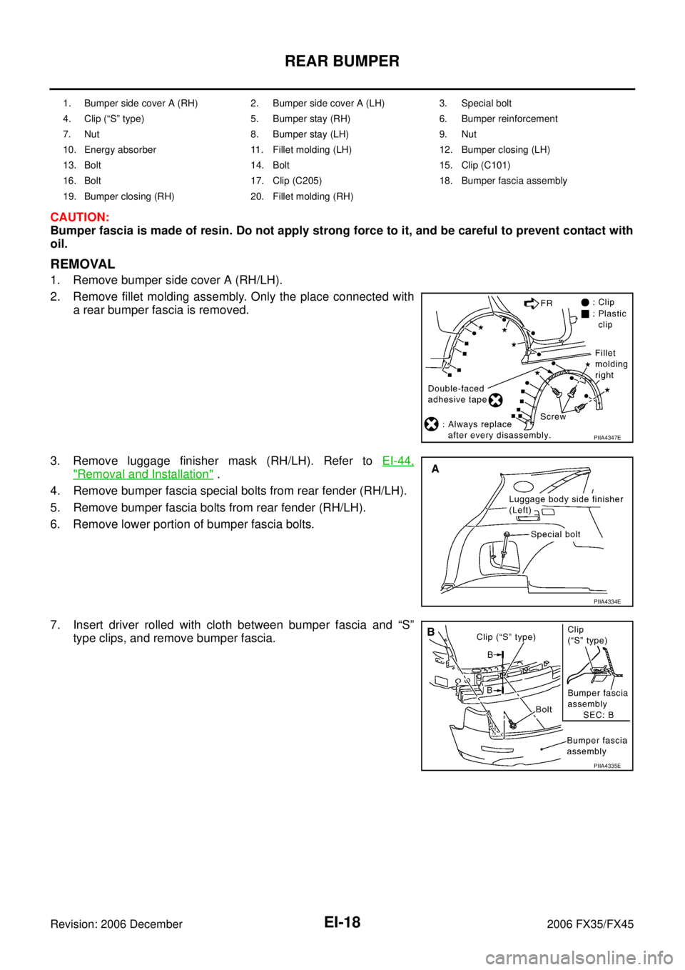
CAUTION:
Bumper fascia is made of resin. Do not apply strong force to it, and be careful to prevent contact with
oil.
REMOVAL
1. Remove bumper side cover A (RH/LH).
2. Remove fillet molding assembly. Only the place connected with a rear bumper fascia is removed.
3. Remove luggage finisher mask (RH/LH). Refer to EI-44,
"Removal and Installation" .
4. Remove bumper fascia special bolts from rear fender (RH/LH).
5. Remove bumper fascia bolts from rear fender (RH/LH).
6. Remove lower portion of bumper fascia bolts.
7. Insert driver rolled with cloth between bumper fascia and “S” type clips, and remove bumper fascia.
1. Bumper side cover A (RH) 2. Bumper side cover A (LH) 3. Special bolt
4. Clip (“S” type) 5. Bumper stay (RH) 6. Bumper reinforcement
7. Nut 8. Bumper stay (LH) 9. Nut
10. Energy absorber 11. Fillet molding (LH) 12. Bumper closing (LH)
13. Bolt 14. Bolt 15. Clip (C101)
16. Bolt 17. Clip (C205) 18. Bumper fascia assembly
19. Bumper closing (RH) 20. Fillet molding (RH)
PIIA4347E
PIIA4334E
PIIA4335E
Page 2767 of 4462
REAR BUMPER EI-19
C
D E
F
G H
J
K L
M A
B
EI
Revision: 2006 December 2006 FX35/FX45
8. Remove bumper fascia assembly. CAUTION:
When removing bumper fascia, 2 workers are required so
as to prevent it from dropping.
9. Remove bumper energy absorber.
10. Remove bumper reinforcement nuts and remove bumper rein- force assembly. Remove nuts with power tool.
11. Remove bumper nuts and remove bumper stay. Remove nuts with power tool.
INSTALLATION
Install in the reverse order of removal.
NOTE:
After installation, adjust the clearance.
DISASSEMBLY AND ASSEMBLY OF REAY BUMPER FASCIA
Disassembly
1. Remove rear fender cover bolt and remove rear fender.
2. Remove bracket clips and remove bracket.
PIIA4336E
PIIA4337E
PIIA4960E
PIIA6416E
Page 2768 of 4462
EI-20
REAR BUMPER
Revision: 2006 December 2006 FX35/FX45
3. Remove rear reflex reflector assembly screw and remove rear reflex reflector assembly.
Assembly
Assemble in the reverse order of disassembly.
REMOVAL AND INSTALLATION OF REAR BUMPER CLOSING
Removal
Remove clips of bumper closing and remove rear bumper closing.
Installation
Install in the reverse order of removal.
REMOVAL AND INSTALLATION OF DRAFTER GUARD
Removal
Remove clips and bolt of drafter guard and remove drafter guard.
Installation
Install in the reverse order of removal.
PIIA6417E
PIIA4954E
PIIA4955E