TROUBLE DIAGNOSIS TF-25
C E F
G H
I
J
K L
M A
B
TF
Revision: 2006 December 2006 FX35/FX45
ACTIVE TEST MODE
Description
Use this mode to determine and identify the details of a malfunction based on self-diagnostic results or data
monitor. AWD control unit gives drive signal to actuator with receiving command from CONSULT-II to check
operation of actuator.
Test Item
CAUTION:
Do not continuously energize for a long time.
AWD CONTROL UNIT PART NUMBER
Ignore the AWD control unit part number displayed in the “ECU PART NUMBER”.
Refer to parts catalog to order the AWD control unit.
Test item Condition Description
ETS S/V
(Detects AWD solenoid valve)
�Vehicle stopped
�Engine running
�No DTC detected
�Change command current value to AWD solenoid, and then change driv-
ing mode. (Monitor value is normal if it is within approximately ±10% of
command value.)
Qu: Increase current value in increments of 0.20A
Qd: Decrease current value in increments of 0.20A
UP: Increase current value in increments of 0.02A
DOWN: Decrease current value in increments of 0.02A
TF-44
TRANSFER ASSEMBLY
Revision: 2006 December 2006 FX35/FX45
TRANSFER ASSEMBLYPFP:33100
Removal and InstallationNDS000AN
REMOVAL
1. Remove tunnel stay with power tool. Refer to RSU-7, "Removal and installation" .
2. Remove exhaust front tube with power tool. Refer to EX-3, "
EXHAUST SYSTEM" .
3. Remove front and rear propeller shaft. Refer to PR-4, "
FRONT PROPELLER SHAFT" and PR-7, "REAR
PROPELLER SHAFT" .
4. Disconnect transfer assembly harness connector and separate harness from transfer assembly.
5. Remove air breather hose. Refer to TF-43, "
AIR BREATHER HOSE" .
6. Support transfer assembly and transmission assembly with a jack.
7. Remove engine rear member with power tool. Refer to EM-113, "
ENGINE ASSEMBLY" (VQ35DE) or
EM-243, "
ENGINE ASSEMBLY" (VK45DE).
8. Remove transfer mounting bolts and separate transfer from transmission. CAUTION:
Secure transfer assembly to a jack.
INSTALLATION
Note the following, and install in the reverse order of removal.
�When installing the transfer to the transmission, install the
mounting bolts following the standard below.
�After the installation, check the fluid level and for fluid leakage.
Refer to TF-9, "
Inspection" .
Bolt No. 1 2 3 4
Quantity 4 3 2 1
Bolt length “ ” mm (in) 75 (2.95) 45 (1.77) 40 (1.57) 30 (1.18)
Tightening torque
N·m (kg-m, ft-lb) 37 (3.8, 27)
SDIA2284E
TROUBLE DIAGNOSES WT-27
C
D
F
G H
I
J
K L
M A
B
WT
Revision: 2006 December 2006 FX35/FX45
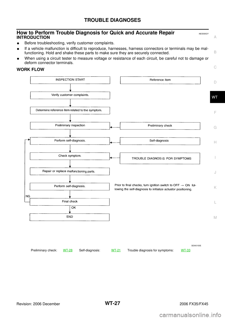
How to Perform Trouble Diagnosis for Quick and Accurate RepairNES000GY
INTRODUCTION
�Before troubleshooting, verify customer complaints.
�If a vehicle malfunction is difficult to reproduce, harnesses, harness connectors or terminals may be mal-
functioning. Hold and shake these parts to make sure they are securely connected.
�When using a circuit tester to measure voltage or resistance of each circuit, be careful not to damage or
deform connector terminals.
WORK FLOW
Preliminary check: WT-28Self-diagnosis:WT-21Trouble diagnosis for symptoms: WT-33
SEIA0100E