Page 3848 of 4462
PB-6
PARKING BRAKE SHOE
Revision: 2006 December 2006 FX35/FX45
PARKING BRAKE SHOEPFP:44060
ComponentsNFS000MS
Removal and InstallationNFS000MT
REMOVAL
WARNING:
Clean brakes with a vacuum dust collector to minimize the hazard of air borne particles or other mate-
rials.
CAUTION:
�Remove wheel, and remove disc rotor with parking brake pedal completely released. Refer to BR-
27, "Removal and Installation of Brake Caliper Assembly" .
�When removing disc rotor, mark both disc rotor and wheel hub for alignment.
1. Remove rear tires from vehicle with a power tool.
2. Remove disc rotor with the parking brake pedal in the completely released position.
3. Remove disc rotor. If disc rotor cannot be removed, remove as follows:
a. Secure the disc rotor in place with wheel nuts and remove adjuster hole plug.
1. Back plate 2. Anchor block 3. Toggle lever
4. Shoe 5. Adjuster 6. Return spring
7. Anti-rattle spring 8. Retainer 9. Anti-rattle pin
SFIA1167E
Page 3919 of 4462

HARNESS PG-67
C
D E
F
G H
I
J
L
M A
B
PG
Revision: 2006 December 2006 FX35/FX45
P/SCKT WW Power Socket
PGC/V EC EVAP Canister Purge Volume Control Solenoid Valve
PHASE EC Camshaft Position Sensor (PHASE)
PHSB1 EC Camshaft Position Sensor (PHASE) (Bank 1)
PHSB2 EC Camshaft Position Sensor (PHASE) (Bank 2)
PNP/SW AT Park/Neutral Position Switch
PNP/SW EC Park/Neutral Position Switch
POS EC Crankshaft Position Sensor (CKPS) (POS)
POWER PG Power Supply Routing
PRE/SE EC EVAP Control System Pressure Sensor
PS/SEN EC Power Steering Pressure Sensor
R/VIEW DI Rear View Camera Control System
ROOM/L LT Interior Room Lamp
RP/SEN EC Refrigerant Pressure Sensor
SEAT SE Power Seat
SEN/PW EC Sensor Power Supply
SHIFT AT A/T Shift Lock System
SNOWSW EC Snow Mode Switch
SROOF RF Sunroof
SRS SRS Supplemental Restraint System
START SC Starting System
STOP/L LT Stop Lamp
STSIG AT Start Signal Circuit
T/WARN WT Low Tire Pressure Warning System
TAIL/L LT Parking, License and Tail Lamps
TPS1 EC Throttle Position Sensor (Sensor 1)
TPS2 EC Throttle Position Sensor (Sensor 2)
TPS3 EC Throttle Position Sensor
TRNSCV BL Homelink Universal Transceiver
TURN LT Turn Signal and Hazard Warning Lamp
VDC BRC Vehicle Dynamics Control System
VEHSEC BL Vehicle Security System
VENT/V EC EVAP Canister Vent Control Valve
VIAS EC Variable Induction Air Control System
VIAS/V EC VIAS Control Solenoid Valve
VSSA/T AT Vehicle Speed Sensor A/T (Revolution Sensor)
WARN DI Warning Lamps
WINDOW GW Power Window
WIP/R WW Rear Wiper and Washer
WIPER WW Front Wiper and Washer Code Section Wiring Diagram Name
Page 3939 of 4462

FRONT PROPELLER SHAFT PR-5
C E F
G H
I
J
K L
M A
B
PR
Revision: 2006 December 2006 FX35/FX45
Removal and InstallationNDS000AV
REMOVAL
1. Remove the front and rear engine undercover with a power tool.
2. Remove the front cross bar with a power tool. Refer to FSU-6, "
FRONT SUSPENSION ASSEMBLY" .
3. Remove the exhaust front tube bracket with a power tool. Refer to EX-3, "
EXHAUST SYSTEM" .
4. Disconnect the heated oxygen sensor harness connector.
5. Remove the exhaust front tube mounting nuts with a power tool. Refer to EX-3, "
EXHAUST SYSTEM" .
6. Remove the right bank three way catalyst with a power tool. Refer to EM-26, "
Removal and Installation"
(VQ35DE), EM-183, "Removal and Installation" (VK45DE).
7. Remove the power steering piping mounting bolts. Refer to PS-
39, "HYDRAULIC LINE" .
8. Remove the power steering gear box fixing bolts to secure work- ing area for removal of propeller shaft. Refer to PS-17, "
POWER
STEERING GEAR AND LINKAGE" .
CAUTION:
Be careful not to damage the steering gear box piping dur-
ing removal.
9. Put matching marks onto propeller shaft flange yoke and final drive companion flange.
CAUTION:
For matching mark, use paint. Do not damage propeller
shaft flange and companion flange.
10. Remove the propeller shaft fixing bolts.
11. Set the transmission jack at the transfer, remove rear engine mounting bolts, and then lower transmission jack about 40 - 50
mm (0.16 - 0.21 in).
12. Remove propeller shaft from the front final drive and transfer.
INSPECTION
�Inspect propeller shaft runout at measuring point. If runout
exceeds specifications, replace propeller shaft assembly. For
measuring point, refer to PR-4, "
Propeller Shaft Runout Measur-
ing Point" .
SDIA1516E
SDIA1517E
SDIA1518E
Propeller shaft runout limit : 0.8 mm (0.031 in)
SPD106
Page 3969 of 4462

POWER STEERING GEAR AND LINKAGE PS-21
C
D E
F
H I
J
K L
M A
B
PS
Revision: 2006 December 2006 FX35/FX45
CAUTION:
�Secure steering gear assembly with a vise, using copper
plates or something similar to prevent it from being dam-
aged. Do not grip cylinder with a vise.
�Before performing disassembly, clean steering gear assem-
bly with kerosene. Be careful not to bring any kerosene into
contact with the discharge and return port connectors.
DISASSEMBLY
1. Remove cylinder tubes from gear housing assembly.
2. Remove rear cover cap from gear housing assembly.
3. Measure adjusting screw height from gear housing assembly, then loosen adjusting screw.
CAUTION:
�Do not turn adjusting screw more than twice.
�Replace steering gear assembly when adjusting screw is
removed or more than twice.
4. Use a rear cover wrench (SST) to remove rear cover from sub- gear assembly.
5. Remove O-ring with a flat-bladed screwdriver, and pull out rear cover.
6. Remove sub-gear assembly from gear housing assembly. CAUTION:
In order to protect oil seal from any damage, pull sub-gear
assembly out straightly.
7. Loosen lock nut of outer socket, and remove outer socket.
8. Remove boot clamps of the small diameter side and the large diameter side, then remove boot.
1. Cotter pin 2. Outer socket 3. Boot clamp
4. Boot 5. Inner socket 6. Boot clamp
7. Gear housing assembly 8. Cylinder tubes 9. Rear cover cap
10. Rear cover 11. O-ring 12. Sub-gear assembly
13. Rack oil seal 14. Rack assembly 15. Rack Teflon ring
16. O-ring 17. End cover assembly
SGIA0544E
SGIA0568E
SGIA0728E
SGIA0508E
Page 3989 of 4462
HYDRAULIC LINE PS-41
C
D E
F
H I
J
K L
M A
B
PS
Revision: 2006 December 2006 FX35/FX45
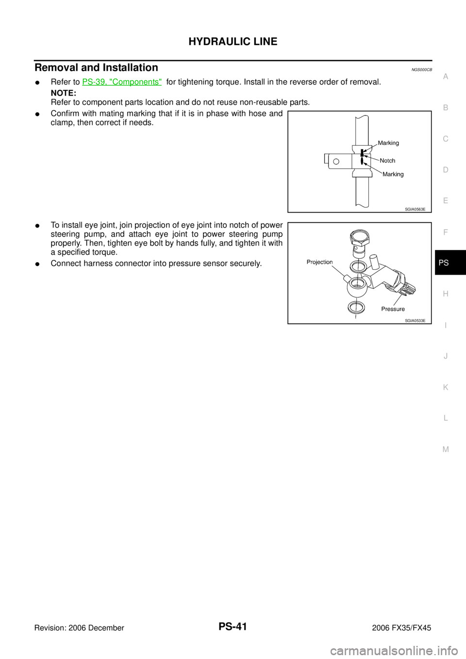
Removal and InstallationNGS000CB
�Refer to PS-39, "Components" for tightening torque. Install in the reverse order of removal.
NOTE:
Refer to component parts location and do not reuse non-reusable parts.
�Confirm with mating marking that if it is in phase with hose and
clamp, then correct if needs.
�To install eye joint, join projection of eye joint into notch of power
steering pump, and attach eye joint to power steering pump
properly. Then, tighten eye bolt by hands fully, and tighten it with
a specified torque.
�Connect harness connector into pressure sensor securely.
SGIA0563E
SGIA0533E
Page 4006 of 4462

RAX-12
REAR DRIVE SHAFT
Revision: 2006 December 2006 FX35/FX45
CAUTION:
If there are any irregular conditions in the component, replace with a new set of housing, ball
cage, steel ball and inner race.
ASSEMBLY
Final Drive Side
1. If plug has been removed, use a drift (SST) to press in a new one.
NOTE:
Discard old plug; replace with new one.
2. Wind serrated part of shaft with tape. Install boot band and boot to shaft. Be careful not to damage boot.
NOTE:
Discard old boot band and boot; replace with each new one.
3. Remove protective tape wound around serrated part of shaft.
4. Install ball cage/steel ball/inner race assembly to shaft, and secure them tightly with a snap ring.
NOTE:
Discard old snap ring; replace with new one.
5. Insert the amount of grease (NISSAN genuine grease or equiva- lent) onto housing (* point) to the quantity mentioned below, and
install it to shaft.
6. Install stopper ring to housing.
7. After installed, pull shaft to check engagement between joint sub-assembly and stopper ring.
SDIA1153E
SFA800
SDIA1125E
Grease amount
VK45DE : 175 − 195 g (6.17 − 6.88 oz)
VQ35DE : 124 − 134 g (4.37 − 4.73 oz)
RAC0678D
Page 4007 of 4462
 shown in the figure.
CAUTION:
If t")
REAR DRIVE SHAFT RAX-13
C E F
G H
I
J
K L
M A
B
RAX
Revision: 2006 December 2006 FX35/FX45
8. Install boot securely into grooves (indicated by * marks) shown in the figure.
CAUTION:
If there is grease on boot mounting surfaces (indicated by *
marks) of shaft and housing, boot may come off. Remove
all grease from surfaces.
9. Make sure boot installation length “L” is the length indicated below. Insert a flat-bladed screwdriver or similar tool into smaller
side of boot. Bleed air from boot to prevent boot deformation.
CAUTION:
�Boot may break if boot installation length is less than standard value.
�Take care not to touch the tip of screwdriver to inside of boot.
10. Secure big and small ends of boot with new boot bands as shown in the figure.
NOTE:
Discard old boot bands; replace with new ones.
11. After installing housing and shaft, rotate boot to check whether or not the actual position is correct. If boot position is not correct,
secure boot with new boot band again.
Wheel Side
1. Insert the amount of grease (NISSAN genuine grease or equiva-
lent) into joint sub-assembly serration hole until grease begins to
ooze from ball groove and serration hole. After insert grease,
use a shop cloth to wipe off old grease that has oozed out.
2. Wind serrated part of shaft with tape. Install boot band and boot to shaft. Be careful not to damage boot.
NOTE:
Discard old boot band and boot; replace with each new one.
3. Remove protective tape wound around serrated part of shaft. Boot installation Length “L ”
VK45DE : 147.9 mm (5.82 in)
VQ35DE : 93.9 mm (3.697 in)
SDIA1738E
SFA395
SDIA1127E
SFA800
Page 4008 of 4462

RAX-14
REAR DRIVE SHAFT
Revision: 2006 December 2006 FX35/FX45
4. Attach circular clip to shaft. At this time, circular clip must fit securely into shaft groove. Attach nut to joint sub-assembly.
Use a wooden hammer to press-fit.
NOTE:
Discard old circular clip; replace with new one.
5. Insert the amount of grease (NISSAN genuine grease or equiva- lent) listed below into housing from large end of boot.
6. Install boot securely into grooves (indicated by * marks) shown in the figure.
CAUTION:
If there is grease on boot mounting surfaces (indicated by *
marks) of shaft and housing, boot may come off. Remove
all grease from surfaces.
7. Make sure boot installation length “L” is the length indicated below. Insert a flat-bladed screwdriver or similar tool into smaller
side of boot. Bleed air from boot to prevent boot deformation.
CAUTION:
�Boot may break if boot installation length is less than standard value.
�Be careful that screwdriver tip does not contact inside surface of boot.
8. Secure big and small ends of boot with new boot bands as shown in the figure.
NOTE:
Discard old boot bands; replace with new ones.
9. After installing joint sub-assembly and shaft, rotate boot to check whether or not the actual position is correct. If boot position is
not correct, secure boot with new boot bands again. Grease amount
VK45DE : 140 − 160 g (4.93 − 5.64 oz)
VQ35DE : 86 − 96 g (3.03 − 3.39 oz)
RAC0049D
Boot installation length “L”
VK45DE : 141.5 mm (5.57 in)
VQ35DE : 97 mm (3.82 in) SDIA1739E
SFA395