Page 3846 of 4462
PB-4
PARKING BRAKE CONTROL
Revision: 2006 December 2006 FX35/FX45
PARKING BRAKE CONTROLPFP:36010
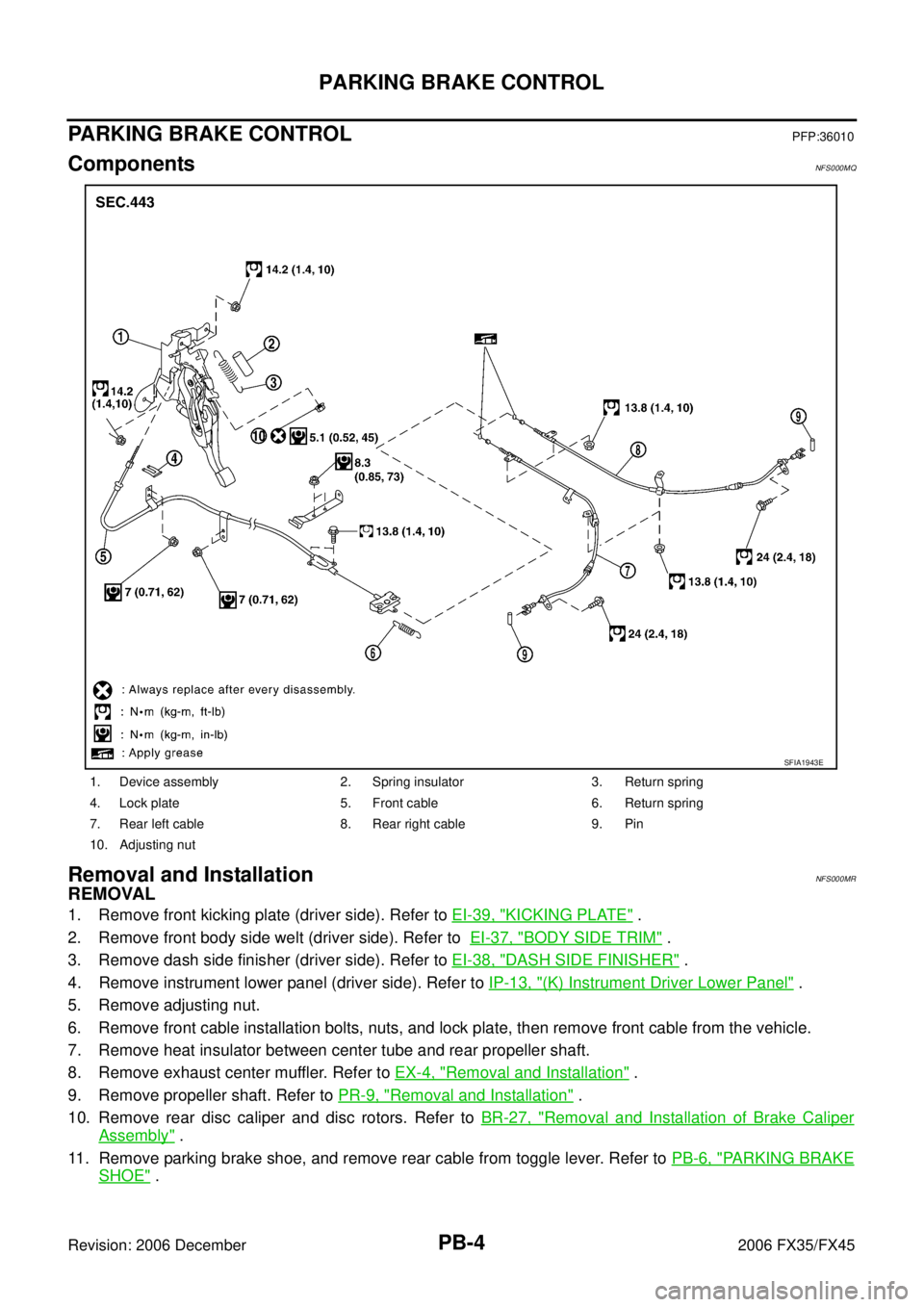
ComponentsNFS000MQ
Removal and InstallationNFS000MR
REMOVAL
1. Remove front kicking plate (driver side). Refer to EI-39, "KICKING PLATE" .
2. Remove front body side welt (driver side). Refer to EI-37, "
BODY SIDE TRIM" .
3. Remove dash side finisher (driver side). Refer to EI-38, "
DASH SIDE FINISHER" .
4. Remove instrument lower panel (driver side). Refer to IP-13, "
(K) Instrument Driver Lower Panel" .
5. Remove adjusting nut.
6. Remove front cable installation bolts, nuts, and lock plate, then remove front cable from the vehicle.
7. Remove heat insulator between center tube and rear propeller shaft.
8. Remove exhaust center muffler. Refer to EX-4, "
Removal and Installation" .
9. Remove propeller shaft. Refer to PR-9, "
Removal and Installation" .
10. Remove rear disc caliper and disc rotors. Refer to BR-27, "
Removal and Installation of Brake Caliper
Assembly" .
11. Remove parking brake shoe, and remove rear cable from toggle lever. Refer to PB-6, "
PARKING BRAKE
SHOE" .
1. Device assembly 2. Spring insulator 3. Return spring
4. Lock plate 5. Front cable 6. Return spring
7. Rear left cable 8. Rear right cable 9. Pin
10. Adjusting nut
SFIA1943E
Page 3848 of 4462
PB-6
PARKING BRAKE SHOE
Revision: 2006 December 2006 FX35/FX45
PARKING BRAKE SHOEPFP:44060
ComponentsNFS000MS
Removal and InstallationNFS000MT
REMOVAL
WARNING:
Clean brakes with a vacuum dust collector to minimize the hazard of air borne particles or other mate-
rials.
CAUTION:
�Remove wheel, and remove disc rotor with parking brake pedal completely released. Refer to BR-
27, "Removal and Installation of Brake Caliper Assembly" .
�When removing disc rotor, mark both disc rotor and wheel hub for alignment.
1. Remove rear tires from vehicle with a power tool.
2. Remove disc rotor with the parking brake pedal in the completely released position.
3. Remove disc rotor. If disc rotor cannot be removed, remove as follows:
a. Secure the disc rotor in place with wheel nuts and remove adjuster hole plug.
1. Back plate 2. Anchor block 3. Toggle lever
4. Shoe 5. Adjuster 6. Return spring
7. Anti-rattle spring 8. Retainer 9. Anti-rattle pin
SFIA1167E
Page 3849 of 4462
PARKING BRAKE SHOE PB-7
C
D E
G H
I
J
K L
M A
B
PB
Revision: 2006 December 2006 FX35/FX45
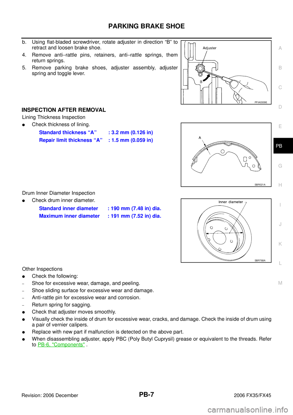
b. Using flat-bladed screwdriver, rotate adjuster in direction “B” to retract and loosen brake shoe.
4. Remove anti −rattle pins, retainers, anti −rattle springs, them
return springs.
5. Remove parking brake shoes, adjuster assembly, adjuster spring and toggle lever.
INSPECTION AFTER REMOVAL
Lining Thickness Inspection
�Check thickness of lining.
Drum Inner Diameter Inspection
�Check drum inner diameter.
Other Inspections
�Check the following:
–Shoe for excessive wear, damage, and peeling.
–Shoe sliding surface for excessive wear and damage.
–Anti-rattle pin for excessive wear and corrosion.
–Return spring for sagging.
�Check that adjuster moves smoothly.
�Visually check the inside of drum for excessive wear, cracks, and damage. Check the inside of drum using
a pair of vernier calipers.
�Replace with new part if malfunction is detected on the above part.
�When disassembling adjuster, apply PBC (Poly Butyl Cuprysil) grease or equivalent to the threads. Refer
to PB-6, "
Components" .
PFIA0309E
Standard thickness “A” : 3.2 mm (0.126 in)
Repair limit thickness “A” : 1.5 mm (0.059 in)
SBR021A
Standard inner diameter : 190 mm (7.48 in) dia.
Maximum inner diameter : 191 mm (7.52 in) dia.
SBR768A
Page 3997 of 4462
PREPARATION RAX-3
C E F
G H
I
J
K L
M A
B
RAX
Revision: 2006 December 2006 FX35/FX45
PREPARATIONPFP:00002
Special Service Tools (SST)NDS000CE
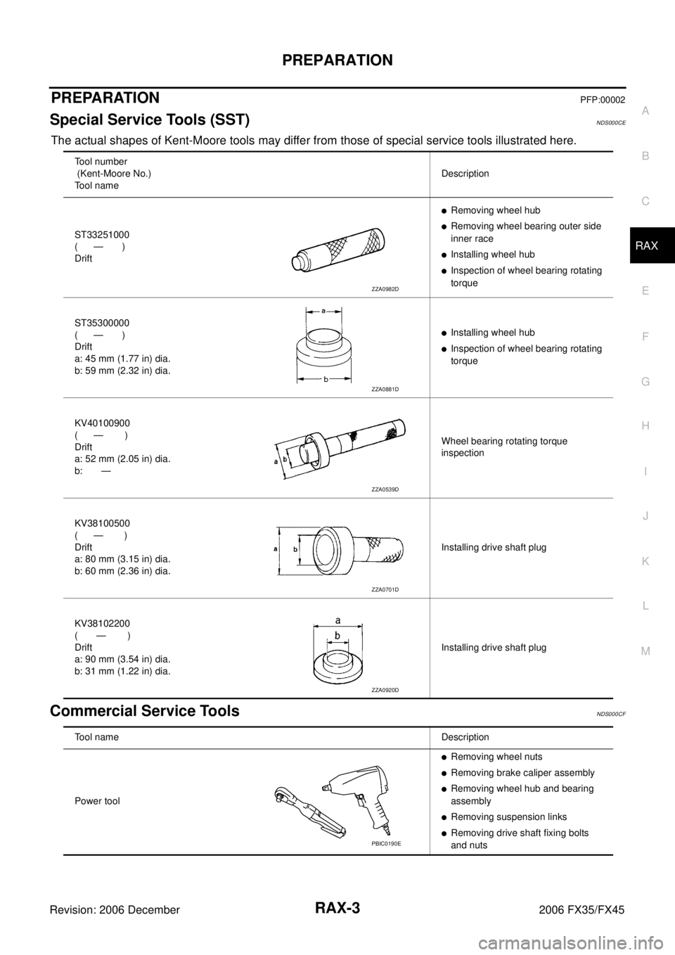
The actual shapes of Kent-Moore tools may differ from those of special service tools illustrated here.
Commercial Service ToolsNDS000CF
Tool number
(Kent-Moore No.)
Tool name Description
ST33251000
( — )
Drift
�Removing wheel hub
�Removing wheel bearing outer side
inner race
�Installing wheel hub
�Inspection of wheel bearing rotating
torque
ST35300000
( — )
Drift
a: 45 mm (1.77 in) dia.
b: 59 mm (2.32 in) dia.
�Installing wheel hub
�Inspection of wheel bearing rotating
torque
KV40100900
( — )
Drift
a: 52 mm (2.05 in) dia.
b: — Wheel bearing rotating torque
inspection
KV38100500
( — )
Drift
a: 80 mm (3.15 in) dia.
b: 60 mm (2.36 in) dia. Installing drive shaft plug
KV38102200
( — )
Drift
a: 90 mm (3.54 in) dia.
b: 31 mm (1.22 in) dia. Installing drive shaft plug
ZZA0982D
ZZA0881D
ZZA0539D
ZZA0701D
ZZA0920D
Tool name
Description
Power tool
�Removing wheel nuts
�Removing brake caliper assembly
�Removing wheel hub and bearing
assembly
�Removing suspension links
�Removing drive shaft fixing bolts
and nutsPBIC0190E
Page 3999 of 4462
REAR WHEEL HUB AND KNUCKLE RAX-5
C E F
G H
I
J
K L
M A
B
RAX
Revision: 2006 December 2006 FX35/FX45
REAR WHEEL HUB AND KNUCKLEPFP:40202
On-Vehicle Inspection NDS000D1
Make sure the mounting conditions (looseness, back lash) of each component and component status (wear,
damage) are normal.
WHEEL BEARING INSPECTION
With the vehicle raised, inspect the following.
�Move wheel hub in the axial direction by hand. Check that there is no looseness of front wheel bearing.
�Rotate wheel hub and make sure there is no unusual noise or other irregular conditions. If there are any
irregular conditions, replace wheel hub and bearing assembly.
Removal and InstallationNDS000CI
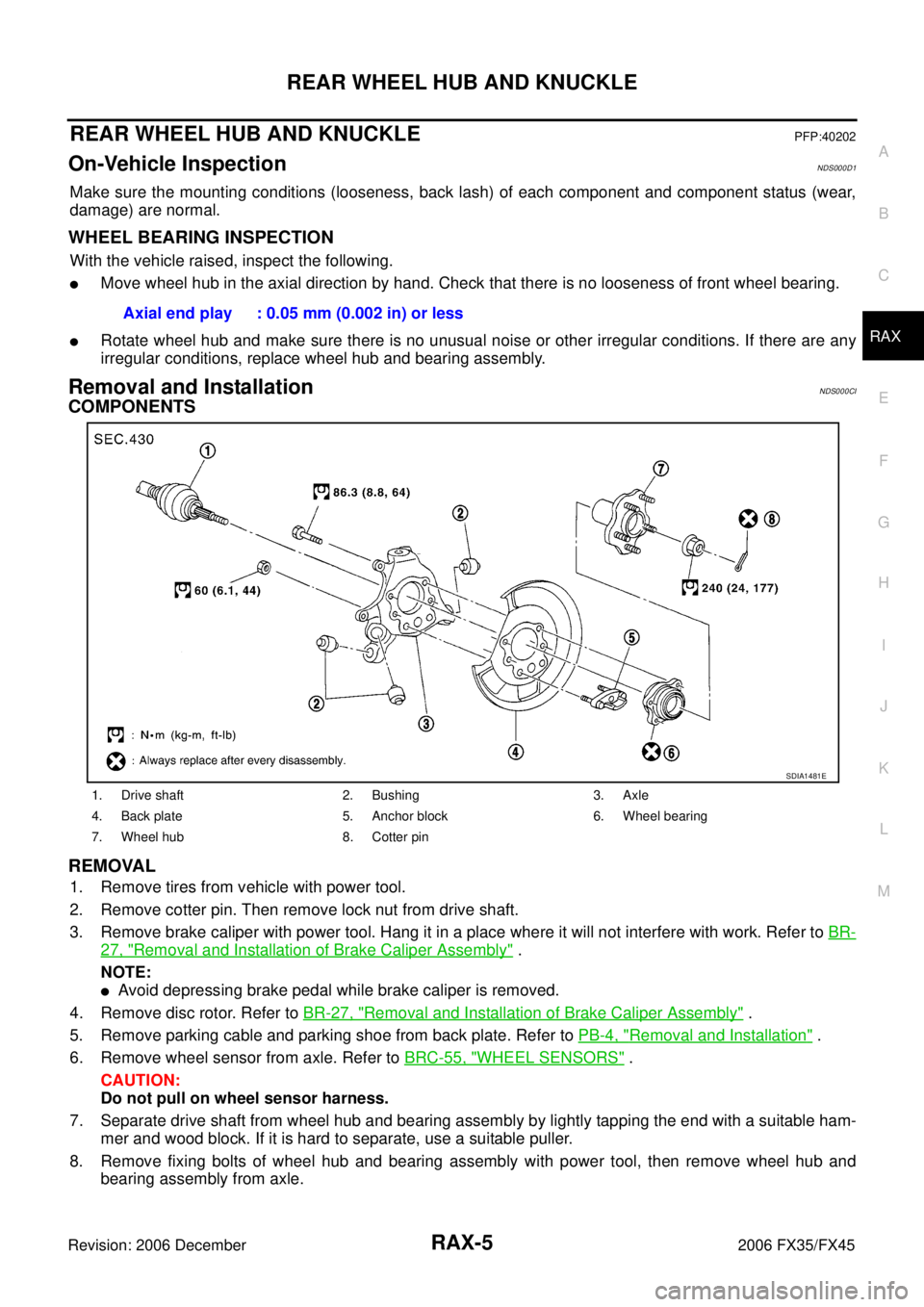
COMPONENTS
REMOVAL
1. Remove tires from vehicle with power tool.
2. Remove cotter pin. Then remove lock nut from drive shaft.
3. Remove brake caliper with power tool. Hang it in a place where it will not interfere with work. Refer to BR-
27, "Removal and Installation of Brake Caliper Assembly" .
NOTE:
�Avoid depressing brake pedal while brake caliper is removed.
4. Remove disc rotor. Refer to BR-27, "
Removal and Installation of Brake Caliper Assembly" .
5. Remove parking cable and parking shoe from back plate. Refer to PB-4, "
Removal and Installation" .
6. Remove wheel sensor from axle. Refer to BRC-55, "
WHEEL SENSORS" .
CAUTION:
Do not pull on wheel sensor harness.
7. Separate drive shaft from wheel hub and bearing assembly by lightly tapping the end with a suitable ham- mer and wood block. If it is hard to separate, use a suitable puller.
8. Remove fixing bolts of wheel hub and bearing assembly with power tool, then remove wheel hub and bearing assembly from axle. Axial end play : 0.05 mm (0.002 in) or less
1. Drive shaft 2. Bushing 3. Axle
4. Back plate 5. Anchor block 6. Wheel bearing
7. Wheel hub 8. Cotter pin
SDIA1481E
Page 4009 of 4462
SERVICE DATA AND SPECIFICATIONS (SDS) RAX-15
C E F
G H
I
J
K L
M A
B
RAX
Revision: 2006 December 2006 FX35/FX45
SERVICE DATA AND SPECIFICATIONS (SDS)PFP:00030
Wheel BearingNDS000CM
Drive ShaftNDS000CN
Axial end play 0.05 mm (0.002 in) or less
Rotational torque At a load of 49,033 N (5,000 kg, 11,000 lb)
Less than 2.7 N·m (0.28 kg-m, 24 in-lb)
Measurement of spring scale Less than 26.6 N (2.7 kg, 5.95 lb)
Measuring point (Brake caliper installation points)
SDIA0801E
Joint Wheel side Final drive side
Engine model VQ35DE VK45DE VQ35DE VK45DE
Grease quantity 86
− 96 g
(3.03 − 3.39 oz) 140
− 160 g
(4.93 − 5.64 oz) 124
− 134 g
(4.37 − 4.73 oz) 175
− 195 g
(6.17 − 6.88 oz)
Boots installed length 97 mm (3.82 in) 141.5 mm (5.57 in) 93.9 mm (3.697 in) 147.9 mm (5.82 in)
Page 4079 of 4462
PREPARATION RSU-3
C
D
F
G H
I
J
K L
M A
B
RSU
Revision: 2006 December 2006 FX35/FX45
PREPARATIONPFP:00002
Special Service Tools (SST)NES000G1
The actual shapes of Kent-Moore tools may differ from those of special service tools illustrated here.
Commercial Service ToolsNES000G2
Tool number
(Kent-Moore No.)
Tool name Description
ST3127S000
(See J −25742-1)
Preload gauge
1. GG91030000
Torque wrench (J −25765)
2. HT62940000 ( — )
Socket adapter (1/2 ″)
3. HT62900000 ( — )
Socket adapter (3/8 ″) Measuring rotating torque of ball joint
NT124
Tool name
Description
Power tool
�Removing wheel nuts
�Removing brake caliper assembly
�Removing rear suspension component
parts
PBIC0190E
Page 4084 of 4462
RSU-8
REAR SUSPENSION ASSEMBLY
Revision: 2006 December 2006 FX35/FX45
REMOVAL
1. Remove tires from vehicle with power tool.
2. Remove brake caliper with power tool. Hang it in a place where it will not interfere with work. Refer to BR-
25, "REAR DISC BRAKE" .
NOTE:
Avoid depressing brake pedal while brake caliper is removed.
3. Remove wheel sensor from rear final drive, then remove wheel sensor harness from rear suspension member.
4. Remove height sensor harness from rear suspension member (if equipped).
5. Remove center muffler and main muffler. Refer to EX-3, "
Components" .
6. Remove stabilizer bar. Refer to RSU-16, "
Removal and Installation" .
7. Remove rear propeller shaft. Refer to PR-9, "
Removal and Installation" .
8. Separate attachments between parking brake cable and vehicle and rear suspension member.
9. Remove rear lower link and coil spring. Refer to RSU-15, "
Removal and Installation" .
10. Remove fixing bolt in lower side of shock absorber with power tool.
11. Set jack under rear final drive.
12. Remove fixing bolts and nuts of tunnel stay and member stay with power tool, then remove those parts from vehicle.
13. Remove fixing bolts and nuts of rear pin stay with power tool and then remove rear pin stay from vehicle.
14. Gradually lowering jack, remove rear suspension assembly.
INSTALLATION
�Refer to RSU-7, "Removal and installation" for tightening torque. Install in the reverse order of removal.
NOTE:
Refer to component parts location and do not reuse non-reusable parts.
�Perform final tightening of installation position of links (rubber bushing) under unladen conditions with tires
on level ground. Check wheel alignment. Refer to RSU-5, "
Wheel Alignment Inspection" .
�After adjusting wheel alignment, adjust neutral position of steering angle sensor. Refer to BRC-6, "Adjust-
ment of Steering Angle Sensor Neutral Position" .
1. Bushing 2. Mounting seal 3. Mounting seal bracket
4. Distance tube 5. Bound bumper cover 6. Bound bumper
7. Shock absorber 8. Upper seat 9. Coil spring
10. Rubber seat 11. Rear lower link 12. Axle assembly
13. Cotter pin 14. Radius rod 15. Front lower link protector
16. Front lower link 17. Stopper rubber 18. Shock absorber assembly
19. Suspension arm 20. Stabilizer connecting rod mounting bracket 21. Stabilizer connecting rod
22. Rear pin stay 23. Rear suspension member 24. Stabilizer bar
25. Stabilizer bushing 26. Stabilizer clamp 27. Member stay
28. Tunnel stay A: With height sensor B: Without height sensor
Refer to GI-11, "
Components" , for the symbols in the figure.