Page 3096 of 4462
![INFINITI FX35 2006 Service Manual FAX-8
[AWD]
PREPARATION
Revision: 2006 December 2006 FX35/FX45
PREPARATIONPFP:00002
Special Service Tools (SST)NDS000C1
The actual shapes of Kent-Moore tools may differ from those of special service t](/manual-img/42/57019/w960_57019-3095.png "INFINITI FX35 2006 Service Manual FAX-8
[AWD]
PREPARATION
Revision: 2006 December 2006 FX35/FX45
PREPARATIONPFP:00002
Special Service Tools (SST)NDS000C1
The actual shapes of Kent-Moore tools may differ from those of special service t")
FAX-8
[AWD]
PREPARATION
Revision: 2006 December 2006 FX35/FX45
PREPARATIONPFP:00002
Special Service Tools (SST)NDS000C1
The actual shapes of Kent-Moore tools may differ from those of special service tools illustrated here.
Commercial Service ToolsNDS000C2
Tool number
(Kent-Moore No.)
Tool name Description
HT72520000
(J −25730-A)
Ball joint remover
a: 33 mm (1.30 in)
b: 50 mm (1.97 in)
r: 11.5 mm (0.453 in)
�Removing steering outer socket
�Removing transverse link
KV40107300
(–)
Boot band crimping tool Installing boot band
KV38107900
(–)
Protector
a: 32 mm (1.26 in) dia. Installing drive shaft
KV38100500
(–)
Drift
a: 80 mm (3.15 in) dia.
b: 60 mm (2.36 in) dia. Installing drive shaft plug
KV38102200
(–)
Drift
a: 90 mm (3.54 in) dia.
b: 31 mm (1.22 in) dia. Installing drive shaft plug
NT546
ZZA1229D
ZZA0835D
ZZA0701D
ZZA0920D
Tool name Description
Power tool
�Removing wheel nuts
�Removing brake caliper assembly
�Removing hub lock nut
�Removing strut lower side
�Removing wheel hub and bearing assembly
�Removing undercoverPBIC0190E
Page 3098 of 4462
![INFINITI FX35 2006 Service Manual FAX-10
[AWD]
FRONT WHEEL HUB AND KNUCKLE
Revision: 2006 December 2006 FX35/FX45
FRONT WHEEL HUB AND KNUCKLEPFP:40202
On-Vehicle Inspection NDS000D0
Make sure the mounting conditions (looseness, back l](/manual-img/42/57019/w960_57019-3097.png "INFINITI FX35 2006 Service Manual FAX-10
[AWD]
FRONT WHEEL HUB AND KNUCKLE
Revision: 2006 December 2006 FX35/FX45
FRONT WHEEL HUB AND KNUCKLEPFP:40202
On-Vehicle Inspection NDS000D0
Make sure the mounting conditions (looseness, back l")
FAX-10
[AWD]
FRONT WHEEL HUB AND KNUCKLE
Revision: 2006 December 2006 FX35/FX45
FRONT WHEEL HUB AND KNUCKLEPFP:40202
On-Vehicle Inspection NDS000D0
Make sure the mounting conditions (looseness, back lash) of each component and component status (wear,
damage) are normal.
WHEEL BEARING INSPECTION
�Move wheel hub in the axial direction by hand. Check that there is no looseness of front wheel bearing.
�Rotate wheel hub and make sure there is no unusual noise or other irregular conditions. If there are any
irregular conditions, replace wheel hub and bearing assembly.
Removal and InstallationNDS000C5
COMPONENTS
REMOVAL
1. Remove tires from vehicle with power tool.
2. Remove brake caliper with power tool. Hang it in a place where it will not interfere with work. Refer to BR-
20, "Removal and Installation of Brake Caliper Assembly" .
NOTE:
Avoid depressing brake pedal while brake caliper is removed.
3. Put alignment marks on disc rotor and wheel hub and bearing assembly, then remove disc rotor.
4. Remove wheel sensor from steering knuckle. Refer to BRC-55,
"WHEEL SENSORS"
CAUTION:
Do not pull on wheel sensor harness.
5. Remove cotter pin, then remove lock nut from drive shaft.
6. Remove steering outer socket and cotter pin at steering knuckle, then loosen mounting nut. Axial end play : 0.05 mm (0.002 in) or less
1. Cotter pin 2. Washer 3. Disc rotor
4. Wheel hub and bearing assembly 5. Splash guard 6. Steering knuckle
Refer to GI-11, "
Components" , for the symbols in the figure.
PDIA1217E
SDIA1480E
Page 3099 of 4462
![INFINITI FX35 2006 Service Manual FRONT WHEEL HUB AND KNUCKLE FAX-11
[AWD]
C E F
G H
I
J
K L
M A
B
FA X
Revision: 2006 December 2006 FX35/FX45
7. Use a ball joint remover (SST) to remove steering outer socket from steering](/manual-img/42/57019/w960_57019-3098.png "INFINITI FX35 2006 Service Manual FRONT WHEEL HUB AND KNUCKLE FAX-11
[AWD]
C E F
G H
I
J
K L
M A
B
FA X
Revision: 2006 December 2006 FX35/FX45
7. Use a ball joint remover (SST) to remove steering outer socket from steering")
FRONT WHEEL HUB AND KNUCKLE FAX-11
[AWD]
C E F
G H
I
J
K L
M A
B
FA X
Revision: 2006 December 2006 FX35/FX45
7. Use a ball joint remover (SST) to remove steering outer socket from steering knuckle. Be careful not to damage ball joint boot.
CAUTION:
To prevent damage to threads and to prevent ball joint
remover (SST) from coming off suddenly, temporarily
tighten mounting nut.
8. Using a puller (suitable tool), remove wheel hub and bearing assembly from drive shaft. NOTE:
�When removing wheel hub and bearing assembly, do not apply an excessive angle to drive shaft joint.
Also be careful not to excessively extend slide joint.
�Do not hang over drive shaft with out support.
9. Remove wheel hub and bearing assembly fixing bolt.
10. Remove splash guard and wheel hub and bearing assembly from steering knuckle.
11. Remove strut assembly and steering knuckle fixing bolts and nuts.
12. Remove transverse link and steering knuckle fixing bolt and nut.
13. Remove steering knuckle from vehicle.
INSPECTION AFTER REMOVAL
Check for deformity, cracks and damage on each parts, replace if necessary.
Ball Joint Inspection
Check for boot breakage, axial looseness, and torque of transverse link and steering outer socket ball joint.
Refer to FSU-14, "
TRANSVERSE LINK" , PS-17, "POWER STEERING GEAR AND LINKAGE" .
INSTALLATION
CAUTION:
Be sure to replace the new differential side oil seal every removal of drive shaft. Refer to FFD-11,
"SIDE OIL SEAL" .
�Refer to FAX-10, "Removal and Installation" for tightening torque. Install in the reverse order of removal.
NOTE:
Refer to component parts location and do not reuse non-reusable parts.
�To assemble disc rotor and wheel hub and bearing assembly,
align the marks.
(When not using the alignment mark, refer to BR-20, "
Removal
and Installation of Brake Caliper Assembly" .)
SGIA0488E
SDIA1480E
Page 3170 of 4462
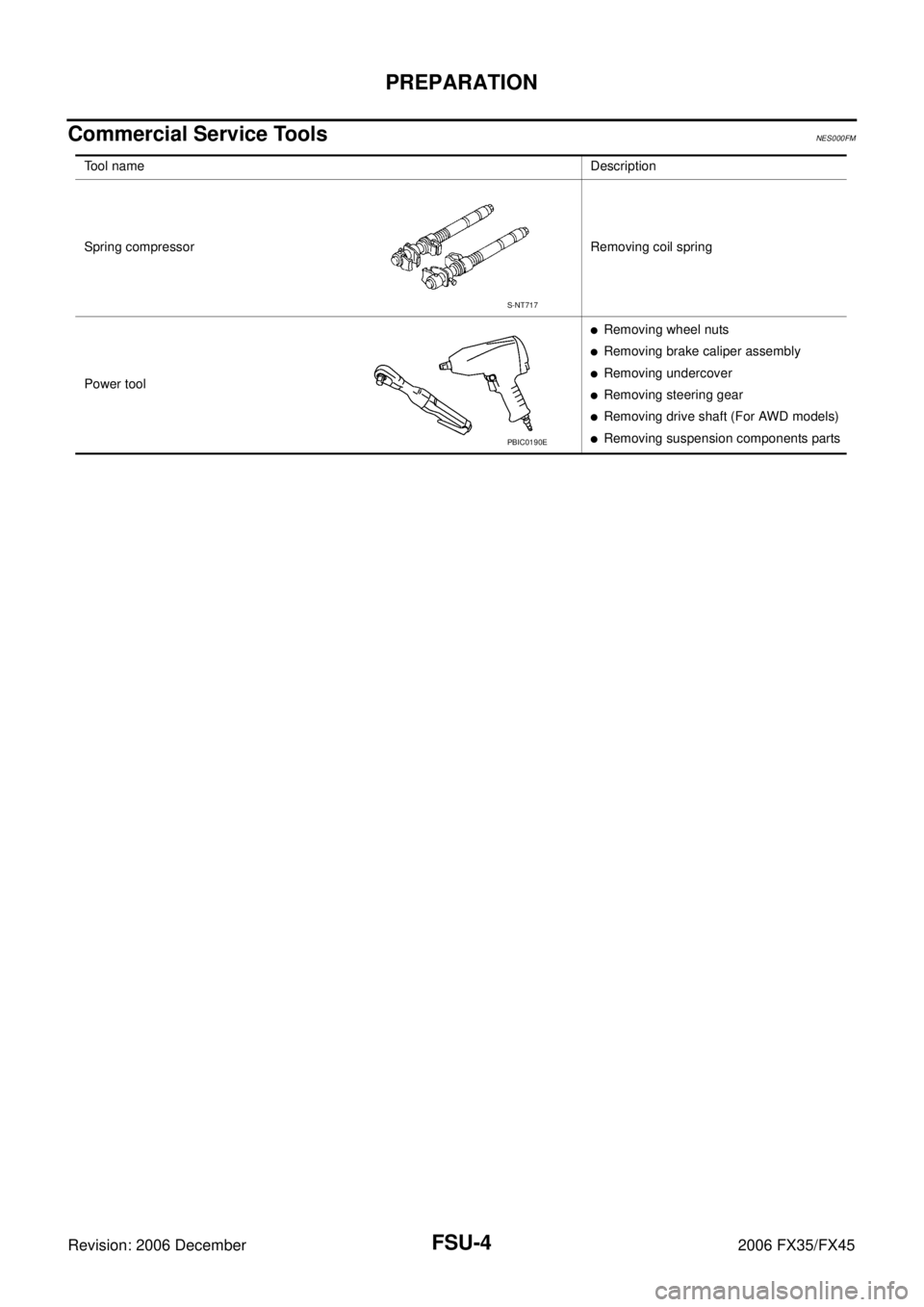
FSU-4
PREPARATION
Revision: 2006 December 2006 FX35/FX45
Commercial Service ToolsNES000FM
Tool name Description
Spring compressor Removing coil spring
Power tool
�Removing wheel nuts
�Removing brake caliper assembly
�Removing undercover
�Removing steering gear
�Removing drive shaft (For AWD models)
�Removing suspension components parts
S-NT717
PBIC0190E
Page 3175 of 4462

FRONT SUSPENSION ASSEMBLY FSU-9
C
D
F
G H
I
J
K L
M A
B
FSU
Revision: 2006 December 2006 FX35/FX45
REMOVAL
1. Set an engine slinger to engine, then suspend engine.
2. Remove tire from vehicle with power tool.
3. Remove brake caliper with power tool. Hang it in a place where it will not interfere with work. Refer to BR-
19, "FRONT DISC BRAKE" .
4. Remove brake hose lock plate. Then remove brake hose from strut assembly.
5. Remove disc rotor.
6. Remove wheel sensor harness from strut assembly. CAUTION:
Do not pull on wheel sensor harness.
7. Remove undercover with power tool.
8. Remove front cross bar.
9. Remove steering hydraulic piping bracket from front suspension member. Refer to PS-39, "
HYDRAULIC LINE" .
10. Remove cotter pin at steering outer socket, then loosen mount- ing nut.
11. Use a ball joint remover (SST) to remove steering outer socket from steering knuckle. Be careful not to damage ball joint boot.
CAUTION:
Tighten temporarily mounting nut to prevent damage to
threads and to prevent ball joint remover (SST) from com-
ing off.
12. Remove mounting bolts of steering gear with power tool, then hang steering gear on vehicle. Refer to PS-17, "
POWER
STEERING GEAR AND LINKAGE" .
13. Remove front final drive side of drive shaft with power tool. (For AWD models) Refer to FAX-12, "
Removal and Installation (Left
Side)" , FA X - 1 3 , "Removal and Installation (Right Side)" .
14. Set jack under front suspension member.
15. Remove fixing bolts and nuts between strut assembly and steering knuckle with power tool.
1. Strut upper plate 2. Strut spacer 3. Mounting insulator
4. Mounting insulator bracket 5. Mounting bearing 6. Spring upper seat
7. Spring upper rubber seat 8. Coil spring 9. Spring lower rubber seat
10. Bound bumper 11. Strut 12. Steering knuckle
13. Front suspension member 14. Transverse link 15. Stabilizer bar
16. Stabilizer bushing 17. Stabilizer clamp 18. Stabilizer connecting rod
19. Front cross bar 20. Cotter pin
Refer to GI-11, "
Components" , for the symbols in the figure.
SEIA0328E
SEIA0329E
SDIA1434E
Page 3802 of 4462

MA-2Revision: 2006 December 2006 FX35/FX45 ROTOR .............................................................
... 36
CALIPER .......................................................... ... 36
PAD .................................................................. ... 36
Checking Steering Gear and Linkage .................. ... 36
STEERING GEAR ............................................ ... 36
STEERING LINKAGE ....................................... ... 36
Checking Power Steering Fluid and Lines ........... ... 37
Axle and Suspension Parts .................................. ... 37
Drive Shaft ........................................................... ... 38
Lubricating Locks, Hinges and Hood Latch ......... ... 38
Checking Seat Belt, Buckles, Retractors, Anchors
and Adjusters ....................................................... ... 39
SERVICE DATA AND SPECIFICATIONS (SDS) ... ... 40
Standard and Limit ............................................... ... 40
BELT DEFLECTION AND TENSION (VQ35DE) ... 40
BELT DEFLECTION AND TENSION (VK45DE) ... 40
ENGINE COOLANT CAPACITY (APPROXI- MATE) (VQ35DE) .............................................
... 40
ENGINE COOLANT CAPACITY (APPROXI-
MATE) (VK45DE) .............................................. ... 40
RADIATOR ........................................................ ... 40
ENGINE OIL CAPACITY (APPROXIMATE)
(VQ35DE) ......................................................... ... 40
ENGINE OIL CAPACITY (APPROXIMATE)
(VK45DE) .......................................................... ... 41
SPARK PLUG (PLATINUM-TIPPED TYPE)
(VQ35DE) ......................................................... ... 41
SPARK PLUG (PLATINUM-TIPPED TYPE)
(VK45DE) .......................................................... ... 41
WHEEL BALANCE ........................................... ... 41
Page 3836 of 4462
MA-36
CHASSIS AND BODY MAINTENANCE
Revision: 2006 December 2006 FX35/FX45
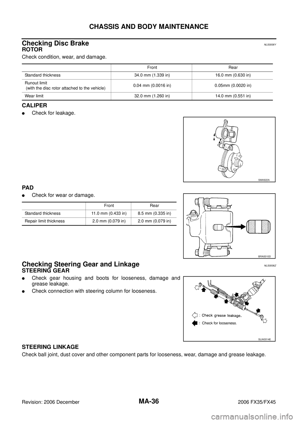
Checking Disc BrakeNLS0006Y
ROTOR
Check condition, wear, and damage.
CALIPER
�Check for leakage.
PA D
�Check for wear or damage.
Checking Steering Gear and LinkageNLS0006Z
STEERING GEAR
�Check gear housing and boots for looseness, damage and
grease leakage.
�Check connection with steering column for looseness.
STEERING LINKAGE
Check ball joint, dust cover and other component parts for looseness, wear, damage and grease leakage.
Front Rear
Standard thickness 34.0 mm (1.339 in) 16.0 mm (0.630 in)
Runout limit
(with the disc rotor attached to the vehicle) 0.04 mm (0.0016 in) 0.05mm (0.0020 in)
Wear limit 32.0 mm (1.260 in) 14.0 mm (0.551 in)
SMA922A
Front Rear
Standard thickness 11.0 mm (0.433 in) 8.5 mm (0.335 in)
Repair limit thickness 2.0 mm (0.079 in) 2.0 mm (0.079 in)
BRA0010D
SLIA0014E
Page 3844 of 4462
PB-2
PREPARATION
Revision: 2006 December 2006 FX35/FX45
PREPARATIONPFP:00002
Commercial Service ToolsNFS000OF
Tool name Description
Power tool Removing caliper assembly, tires
PBIC0190E