Page 204 of 4462
AT-120
DTC P0720 VEHICLE SPEED SENSOR A/T (REVOLUTION SENSOR)
Revision: 2006 December 2006 FX35/FX45
Wiring Diagram — AT — VSSA/TNCS001CN
TCWM0249E
Page 219 of 4462
DTC P1710 A/T FLUID TEMPERATURE SENSOR CIRCUIT AT-135
D E
F
G H
I
J
K L
M A
B
AT
Revision: 2006 December 2006 FX35/FX45
Wiring Diagram — AT — FTSNCS001DY
TCWM0251E
Page 251 of 4462
DTC P1815 MANUAL MODE SWITCH AT-167
D E
F
G H
I
J
K L
M A
B
AT
Revision: 2006 December 2006 FX35/FX45
Wiring Diagram — AT — MMSWNCS001GI
TCWM0498E
Page 263 of 4462
MAIN POWER SUPPLY AND GROUND CIRCUIT AT-179
D E
F
G H
I
J
K L
M A
B
AT
Revision: 2006 December 2006 FX35/FX45
MAIN POWER SUPPLY AND GROUND CIRCUITPFP:00100
Wiring Diagram — AT — MAINNCS001H9
TCWM0497E
Page 268 of 4462

AT-184
BRAKE SIGNAL CIRCUIT
Revision: 2006 December 2006 FX35/FX45
BRAKE SIGNAL CIRCUITPFP:25320
CONSULT-II Reference ValueNCS001HD
Diagnostic ProcedureNCS001HE
1. CHECK CAN COMMUNICATION LINE
Perform the self-diagnosis. Refer to AT- 9 2 , "
SELF-DIAGNOSTIC RESULT MODE" , AT- 1 0 2 , "Diagnostic Pro-
cedure without CONSULT-II" .
Is a malfunction in the CAN communication indicated in the results?
YES >> Check CAN communication line. Refer to AT- 1 0 4 , "DTC U1000 CAN COMMUNICATION LINE" .
NO >> GO TO 2.
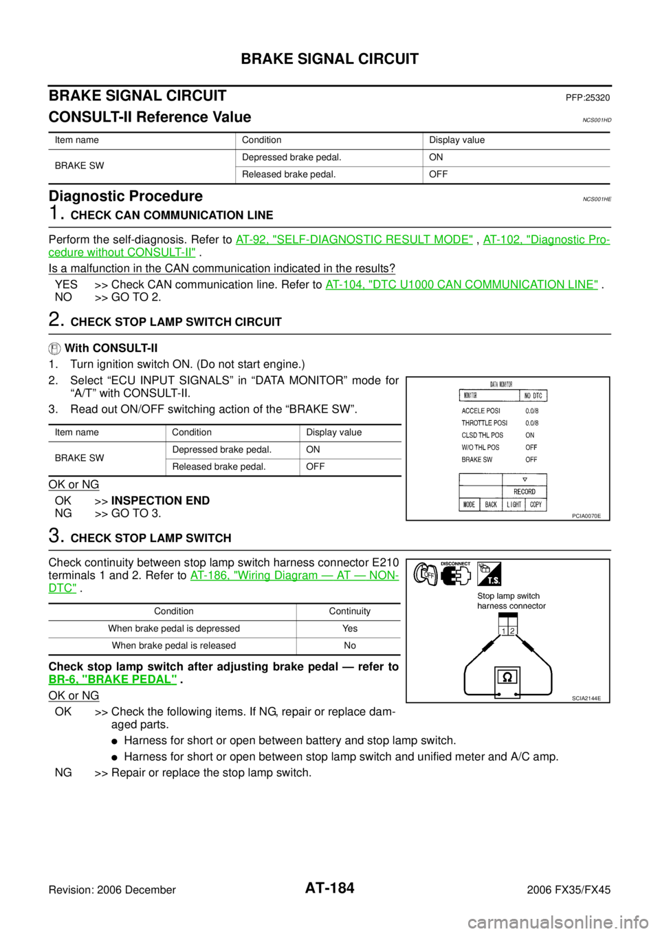
2. CHECK STOP LAMP SWITCH CIRCUIT
With CONSULT-II
1. Turn ignition switch ON. (Do not start engine.)
2. Select “ECU INPUT SIGNALS” in “DATA MONITOR” mode for “A/T” with CONSULT-II.
3. Read out ON/OFF switching action of the “BRAKE SW”.
OK or NG
OK >> INSPECTION END
NG >> GO TO 3.
3. CHECK STOP LAMP SWITCH
Check continuity between stop lamp switch harness connector E210
terminals 1 and 2. Refer to AT- 1 8 6 , "
Wiring Diagram — AT — NON-
DTC" .
Check stop lamp switch after adjusting brake pedal — refer to
BR-6, "
BRAKE PEDAL" .
OK or NG
OK >> Check the following items. If NG, repair or replace dam- aged parts.
�Harness for short or open between battery and stop lamp switch.
�Harness for short or open between stop lamp switch and unified meter and A/C amp.
NG >> Repair or replace the stop lamp switch.
Item name Condition Display value
BRAKE SW Depressed brake pedal. ON
Released brake pedal. OFF
Item name Condition Display value
BRAKE SW Depressed brake pedal. ON
Released brake pedal. OFF
PCIA0070E
Condition Continuity
When brake pedal is depressed Yes When brake pedal is released No
SCIA2144E
Page 270 of 4462
AT-186
TROUBLE DIAGNOSIS FOR SYMPTOMS
Revision: 2006 December 2006 FX35/FX45
TROUBLE DIAGNOSIS FOR SYMPTOMSPFP:00007
Wiring Diagram — AT — NONDTCNCS001HI
TCWM0500E
Page 317 of 4462
A/T SHIFT LOCK SYSTEM AT-233
D E
F
G H
I
J
K L
M A
B
AT
Revision: 2006 December 2006 FX35/FX45
Wiring Diagram — AT — SHIFTNCS001IB
TCWM0503E
Page 318 of 4462

AT-234
A/T SHIFT LOCK SYSTEM
Revision: 2006 December 2006 FX35/FX45
Diagnostic ProcedureNCS001IC
SYMPTOM 1:
�Selector lever cannot be moved from “P” position with key in ON position and brake pedal
applied.
�Selector lever can be moved from “P” position with key in ON position and brake pedal released.
�Selector lever can be moved from “P” position when key is removed from key cylinder.
SYMPTOM 2:
�Ignition key cannot be removed when selector lever is set to “P” position.
�Ignition key can be removed when selector lever is set to any position except “P” position.
1. CHECK KEY INTERLOCK CABLE
Check the key interlock cable for damage.
OK or NG
OK >> GO TO 2.
NG >> Repair or replace key interlock cable. Refer to AT- 2 3 6 , "
KEY INTERLOCK CABLE" .
2. CHECK SELECTOR LEVER POSITION
Check the selector lever position for damage. Refer to AT- 2 3 1 , "
Checking of A/T Position"
OK or NG
OK >> GO TO 3.
NG >> Adjust A/T position. Refer to AT- 2 3 1 , "
Adjustment of A/T Position" .
3. CHECK SHIFT LOCK SOLENOID AND PARK POSITION SWITCH
1. Connect A/T device harness connector.
2. Turn ignition switch ON. (Do not start engine.)
3. Selector lever is set in “P” position.
4. Check operation.
OK or NG
OK >> INSPECTION END
NG >> GO TO 4.
4. CHECK POWER SOURCE
1. Turn ignition switch ON. (Do not start engine.)
2. Check the voltage between A/T device harness connector M67 terminal 1 and ground. Refer to AT- 2 3 3 , "
Wiring Diagram — AT
— SHIFT" .
OK or NG
OK >> GO TO 7.
NG >> GO TO 5.
Condition Brake pedal Operation
When ignition switch is turned to ON and selector lever is set in
“P” position. Depressed Yes
Released No
Condition Brake pedal Data (Approx.)
When ignition switch is turned to
ON. Depressed Battery voltage
Released 0 V
SCIA2122E