Page 369 of 4462
OVERHAUL AT-285
D E
F
G H
I
J
K L
M A
B
AT
Revision: 2006 December 2006 FX35/FX45
7. Pawl shaft 8. Self-sealing bolt 9. Seal ring
10. Needle bearing 11. Gasket 12. Revolution sensor
13. Parking gear 14. Output shaft 15. Bearing race
16. Needle bearing 17. Manual plate 18. Parking rod
19. Manual shaft oil seal 20. Manual shaft 21. O-ring
22. Band servo anchor end pin 23. Detent spring 24. Spacer
25. Seal ring 26. Snap ring 27. Return spring
28. O-ring 29. Servo assembly 30. Snap ring
31. Sub-harness 32. Control valve with TCM 33. Bracket
34. A/T fluid temperature sensor 2 35. Oil pan 36. Magnet
37. Drain plug 38. Drain plug gasket 39. Oil pan mounting bolt
40. Oil pan gasket 41. Terminal cord assembly 42. O-ring
43. Retaining pin 44. Transmission case
Refer to GI section to make sure icons (symbol marks) in the figure. Refer to GI-11, "
Components" .
Page 371 of 4462
OVERHAUL AT-287
D E
F
G H
I
J
K L
M A
B
AT
Revision: 2006 December 2006 FX35/FX45
7. Return spring 8. Pawl shaft 9. Seal ring
10. Needle bearing 11. Gasket 12. Revolution sensor
13. Parking gear 14. Output shaft 15. Bearing race
16. Needle bearing 17. Manual plate 18. Parking rod
19. Manual shaft oil seal 20. Manual shaft 21. O-ring
22. Band servo anchor end pin 23. Detent spring 24. Spacer
25. Seal ring 26. Snap ring 27. Return spring
28. O-ring 29. Servo assembly 30. Snap ring
31. Sub-harness 32. Control valve with TCM 33. Bracket
34. A/T fluid temperature sensor 2 35. Oil pan 36. Magnet
37. Drain plug 38. Drain plug gasket 39. Oil pan mounting bolt
40. Oil pan gasket 41. Terminal cord assembly 42. O-ring
43. Retaining pin 44. Transmission case
Refer to GI section to make sure icons (symbol marks) in the figure. Refer to GI-11, "
Components" .
Page 378 of 4462
AT-294
DISASSEMBLY
Revision: 2006 December 2006 FX35/FX45
DISASSEMBLYPFP:31020
DisassemblyNCS001IP
CAUTION:
Do not disassemble parts behind drum support. Refer to AT- 1 8 , "
Cross-sectional View (2WD Models)"
, AT- 1 9 , "Cross-sectional View (VQ35DE Models for AWD)" or AT- 2 0 , "Cross-sectional View (VK45DE
Models for AWD)" .
1. Drain ATF through drain plug.
2. Remove torque converter by holding it firmly and turing while pulling straight out.
3. Check torque converter one-way clutch using check tool as shown in the figure.
a. Insert check tool into the groove of bearing support built into one-way clutch outer race.
b. When fixing bearing support with check tool, rotate one-way clutch spline using screwdriver.
c. Make sure that inner race rotates clockwise only. If not, replace torque converter assembly.
4. Remove converter housing from transmission case. CAUTION:
Be careful not to scratch converter housing.
SCIA5010E
SCIA3171E
SCIA3427E
Page 441 of 4462

ASSEMBLY AT-357
D E
F
G H
I
J
K L
M A
B
AT
Revision: 2006 December 2006 FX35/FX45
15. Install snap ring to A/T assembly harness connector.
16. Install magnets in oil pan.
17. Install oil pan to transmission case.
a. Install oil pan gasket to transmission case. CAUTION:
�Do not reuse oil pan gasket.
�Install it in the direction to align hole positions.
�Complete remove all moisture, oil and old gasket, etc. from oil pan gasket mounting surface.
b. Install oil pan to transmission case. CAUTION:
�Install it so that drain plug comes to the position as
shown in the figure.
�Be careful not to pinch harnesses.
�Completely remove all moisture, oil and old gasket, etc.
from oil pan gasket mounting surface.
c. Tighten oil pan mounting bolts to the specified torque in numeri- cal order shown in the figure after temporarily tightening them.
Refer to AT- 2 7 4 , "
Components" .
CAUTION:
Do not reuse oil pan mounting bolts.
18. Install drain plug to oil pan, and then tighten drain plug mounting bolts to the specified torque. Refer to AT- 2 7 4 , "
Components" .
CAUTION:
Do not reuse drain plug gasket.
SCIA5300E
SCIA5200E
SCIA2308E
SCIA4113E
Page 442 of 4462
AT-358
ASSEMBLY
Revision: 2006 December 2006 FX35/FX45
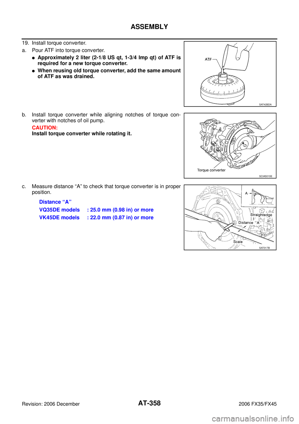
19. Install torque converter.
a. Pour ATF into torque converter.
�Approximately 2 liter (2-1/8 US qt, 1-3/4 Imp qt) of ATF is
required for a new torque converter.
�When reusing old torque converter, add the same amount
of ATF as was drained.
b. Install torque converter while aligning notches of torque con- verter with notches of oil pump.
CAUTION:
Install torque converter while rotating it.
c. Measure distance “A” to check that torque converter is in proper position.
SAT428DA
SCIA5010E
Distance “A”
VQ35DE models : 25.0 mm (0.98 in) or more
VK45DE models : 22.0 mm (0.87 in) or more
SAT017B
Page 475 of 4462

LUBRICANT ATC-29
C
D E
F
G H
I
K L
M A
B
AT C
Revision: 2006 December 2006 FX35/FX45
LUBRICANT ADJUSTING PROCEDURE FOR COMPRESSOR REPLACEMENT
1. Before connecting recovery/recycling recharging equipment to vehicle, check recovery/recycling recharg- ing equipment gauges. No refrigerant pressure should be displayed. If NG, recover refrigerant from equip-
ment lines.
2. Connect recovery/recycling recharging equipment to vehicle. Confirm refrigerant purity in supply tank using recovery/recycling recharging equipment and refrigerant identifier. If NG, refer to AT C - 7 , "
CONTAM-
INATED REFRIGERANT" .
3. Confirm refrigerant purity in vehicle A/C system using recovery/recycling recharging equipment and refrig- erant identifier. If NG, refer to AT C - 7 , "
CONTAMINATED REFRIGERANT" .
4. Discharge refrigerant into the refrigerant recovery/recycling equipment. Measure lubricant discharged into the recovery/recycling equipment.
5. Drain the lubricant from the old (removed) compressor into a graduated container and recover the amount of lubricant drained.
6. Drain the lubricant from the new compressor into a separate, clean container.
7. Measure an amount of new lubricant installed equal to amount drained from old compressor. Add this lubricant to new compressor through the suction port opening.
8. Measure an amount of new lubricant equal to the amount recovered during discharging. Add this lubricant to new compressor through the suction port opening.
9. If the liquid tank also needs to be replaced, add another 5 m (0.2 US fl oz., 0.2 Imp fl oz.) of lubricant at this time.
Do not add this 5 m (0.2 US fl oz., 0.2 Imp fl oz.) of lubricant when replaces the compressor only.
RJIA3578E
Page 543 of 4462

TROUBLE DIAGNOSIS ATC-97
C
D E
F
G H
I
K L
M A
B
AT C
Revision: 2006 December 2006 FX35/FX45
Low-pressure Side Sometimes Becomes Negative
Low-pressure Side Becomes Negative
DIAGNOSIS PROCEDURE FOR INSUFFICIENT COOLING
SYMPTOM: Insufficient cooling
1. CHECK POWER SUPPLY FOR ECV (ELECTRONIC CONTROL VALVE)
1. Disconnect compressor (ECV) connector.
2. Turn ignition switch ON.
3. Check voltage between compressor (ECV) harness connector F6 terminal 2 and ground.
OK or NG
OK >> GO TO 2.
NG >> Check power supply circuit and 10A fuse [No. 12, located in the fuse block (J/B)]. Refer to PG-81, "
FUSE
BLOCK - JUNCTION BOX (J/B)" .
�If fuse is OK, check harness for open circuit. Repair or replace if necessary.
�If fuse is NG, check harness for short circuit and replace fuse.
Gauge indication Refrigerant cycle Probable cause Corrective action
Low-pressure side sometimes
becomes negative.
�Air conditioning system
does not function and does
not cyclically cool the com-
partment air.
�The system constantly func-
tions for a certain period of
time after compressor is
stopped and restarted. Refrigerant does not dis-
charge cyclically.
↓
Moisture is frozen at expan-
sion valve outlet and inlet.
↓
Water is mixed with refriger-
ant.
�Drain water from refrigerant
or replace refrigerant.
�Replace liquid tank.
AC354A
Gauge indication Refrigerant cycle Probable cause Corrective action
Low-pressure side becomes nega-
tive.
Liquid tank or front/rear side of
expansion valve’s pipe is
frosted or wet with dew. High-pressure side is closed
and refrigerant does not flow.
↓
Expansion valve or liquid tank
is frosted. Leave the system at rest until
no frost is present. Start it
again to check whether or not
the malfunction is caused by
water or foreign particles.
�If water is the cause, initially
cooling is okay. Then the
water freezes causing a
blockage. Drain water from
refrigerant or replace refrig-
erant.
�If due to foreign particles,
remove expansion valve
and remove the particles
with dry and compressed air
(not shop air).
�If either of the above meth-
ods cannot correct the mal-
function, replace expansion
valve.
�Replace liquid tank.
�Check lubricant for contami-
nation.
AC362A
2 – ground : Battery voltage
RJIA2294E
Page 571 of 4462

HEATER & COOLING UNIT ASSEMBLY ATC-125
C
D E
F
G H
I
K L
M A
B
AT C
Revision: 2006 December 2006 FX35/FX45
HEATER & COOLING UNIT ASSEMBLYPFP:27110
Removal and InstallationNJS000EU
REMOVAL
1. Use a refrigerant collecting equipment (for HFC-134a) to discharge the refrigerant.
2. Drain coolant from cooling system. Refer to CO-11, "
Changing Engine Coolant" (VQ35DE) or CO-38,
"Changing Engine Coolant" (VK45DE).
3. Remove cowl top cover. Refer to EI-23, "
COWL TOP" .
4. Remove high-pressure pipe 2 mounting clip.
5. Remove low-pressure flexible hose bracket mounting bolt. Refer to ATC-146, "
Removal and Installation of
Low-pressure Flexible Hose" .
6. Disconnect low-pressure pipe 1 and high-pressure pipe 2 from evaporator.
a. Set a disconnector [high-pressure side (SST: 9253089908), low- pressure side (SST: 9253089916)] on A/C piping.
b. Slide a disconnector toward vehicle front until it clicks.
c. Slide A/C piping toward vehicle front and disconnect it.
CAUTION:
Cap or wrap the joint of the pipe with suitable material such
as vinyl tape to avoid the entry of air.
7. Remove electric throttle control actuator (VQ35DE). Refer to EM-19, "
INTAKE MANIFOLD COLLECTOR" .
8. Disconnect two heater hoses from heater core.
9. Remove instrument panel assembly. Refer to IP-10, "
INSTRUMENT PANEL ASSEMBLY" .
10. Remove blower unit. Refer to ATC-120, "
BLOWER UNIT" .
RJIA2037E
RJIA2041E
RJIA2077E