Page 1323 of 4462
WARNING CHIME DI-73
C
D E
F
G H
I
J
L
M A
B
DI
Revision: 2006 December 2006 FX35/FX45
2. CHECK UNIFIED METER AND A/C AMP. INPUT SIGNAL
1. Select “METER A/C AMP” on CONSULT-II.
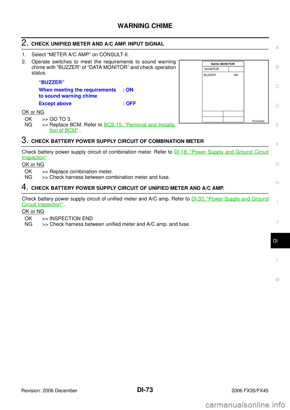
2. Operate switches to meet the requirements to sound warning chime with “BUZZER” of “DATA MONITOR” and check operation
status.
OK or NG
OK >> GO TO 3.
NG >> Replace BCM. Refer to BCS-15, "
Removal and Installa-
tion of BCM" .
3. CHECK BATTERY POWER SUPPLY CIRCUIT OF COMBINATION METER
Check battery power supply circuit of combination meter. Refer to DI-18, "
Power Supply and Ground Circuit
Inspection" .
OK or NG
OK >> Replace combination meter.
NG >> Check harness between combination meter and fuse.
4. CHECK BATTERY POWER SUPPLY CIRCUIT OF UNIFIED METER AND A/C AMP.
Check battery power supply circuit of unified meter and A/C amp. Refer to DI-33, "
Power Supply and Ground
Circuit Inspection" .
OK or NG
OK >> INSPECTION END
NG >> Check harness between unified meter and A/C amp. and fuse. “BUZZER”
When meeting the requirements
to sound warning chime : ON
Except above : OFF
PKIA2063E
Page 1324 of 4462
DI-74
WARNING CHIME
Revision: 2006 December 2006 FX35/FX45
Front Door Switch (Driver Side) Signal InspectionNKS003I5
1. CHECK BCM INPUT SIGNAL
With CONSULT-ll
1. Select “BCM”.
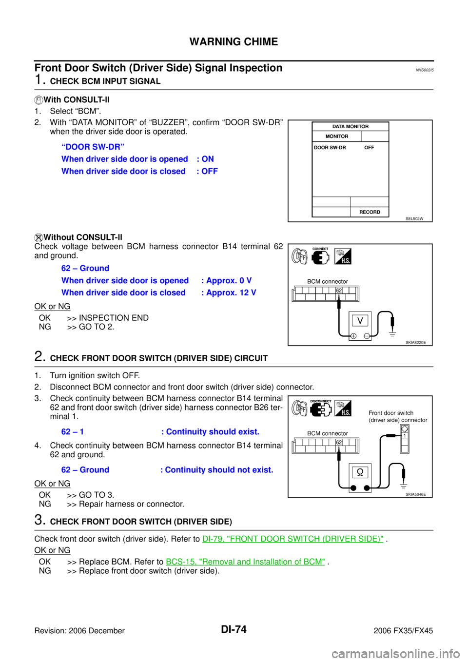
2. With “DATA MONITOR” of “BUZZER”, confirm “DOOR SW-DR” when the driver side door is operated.
Without CONSULT-ll
Check voltage between BCM harness connector B14 terminal 62
and ground.
OK or NG
OK >> INSPECTION END
NG >> GO TO 2.
2. CHECK FRONT DOOR SWITCH (DRIVER SIDE) CIRCUIT
1. Turn ignition switch OFF.
2. Disconnect BCM connector and front door switch (driver side) connector.
3. Check continuity between BCM harness connector B14 terminal 62 and front door switch (driver side) harness connector B26 ter-
minal 1.
4. Check continuity between BCM harness connector B14 terminal 62 and ground.
OK or NG
OK >> GO TO 3.
NG >> Repair harness or connector.
3. CHECK FRONT DOOR SWITCH (DRIVER SIDE)
Check front door switch (driver side). Refer to DI-79, "
FRONT DOOR SWITCH (DRIVER SIDE)" .
OK or NG
OK >> Replace BCM. Refer to BCS-15, "Removal and Installation of BCM" .
NG >> Replace front door switch (driver side). “DOOR SW-DR”
When driver side door is opened : ON
When driver side door is closed : OFF
SEL502W
62 – Ground
When driver side door is opened : Approx. 0 V
When driver side door is closed : Approx. 12 V
SKIA8220E
62 – 1 : Continuity should exist.
62 – Ground : Continuity should not exist.
SKIA5046E
Page 1326 of 4462
DI-76
WARNING CHIME
Revision: 2006 December 2006 FX35/FX45
4. CHECK KEY SWITCH POWER SUPPLY CIRCUIT
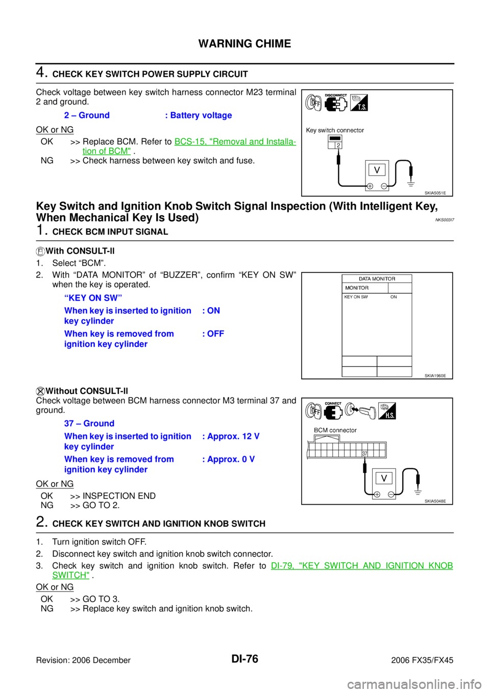
Check voltage between key switch harness connector M23 terminal
2 and ground.
OK or NG
OK >> Replace BCM. Refer to BCS-15, "Removal and Installa-
tion of BCM" .
NG >> Check harness between key switch and fuse.
Key Switch and Ignition Knob Switch Signal Inspection (With Intelligent Key,
When Mechanical Key Is Used)
NKS003I7
1. CHECK BCM INPUT SIGNAL
With CONSULT-ll
1. Select “BCM”.
2. With “DATA MONITOR” of “BUZZER”, confirm “KEY ON SW” when the key is operated.
Without CONSULT-ll
Check voltage between BCM harness connector M3 terminal 37 and
ground.
OK or NG
OK >> INSPECTION END
NG >> GO TO 2.
2. CHECK KEY SWITCH AND IGNITION KNOB SWITCH
1. Turn ignition switch OFF.
2. Disconnect key switch and ignition knob switch connector.
3. Check key switch and ignition knob switch. Refer to DI-79, "
KEY SWITCH AND IGNITION KNOB
SWITCH" .
OK or NG
OK >> GO TO 3.
NG >> Replace key switch and ignition knob switch. 2 – Ground : Battery voltage
SKIA5051E
“KEY ON SW”
When key is inserted to ignition
key cylinder : ON
When key is removed from
ignition key cylinder : OFF
SKIA1960E
37 – Ground
When key is inserted to ignition
key cylinder : Approx. 12 V
When key is removed from
ignition key cylinder : Approx. 0 V
SKIA5048E
Page 1327 of 4462
WARNING CHIME DI-77
C
D E
F
G H
I
J
L
M A
B
DI
Revision: 2006 December 2006 FX35/FX45
3. CHECK KEY SWITCH AND IGNITION KNOB SWITCH CIRCUIT
1. Disconnect BCM connector.
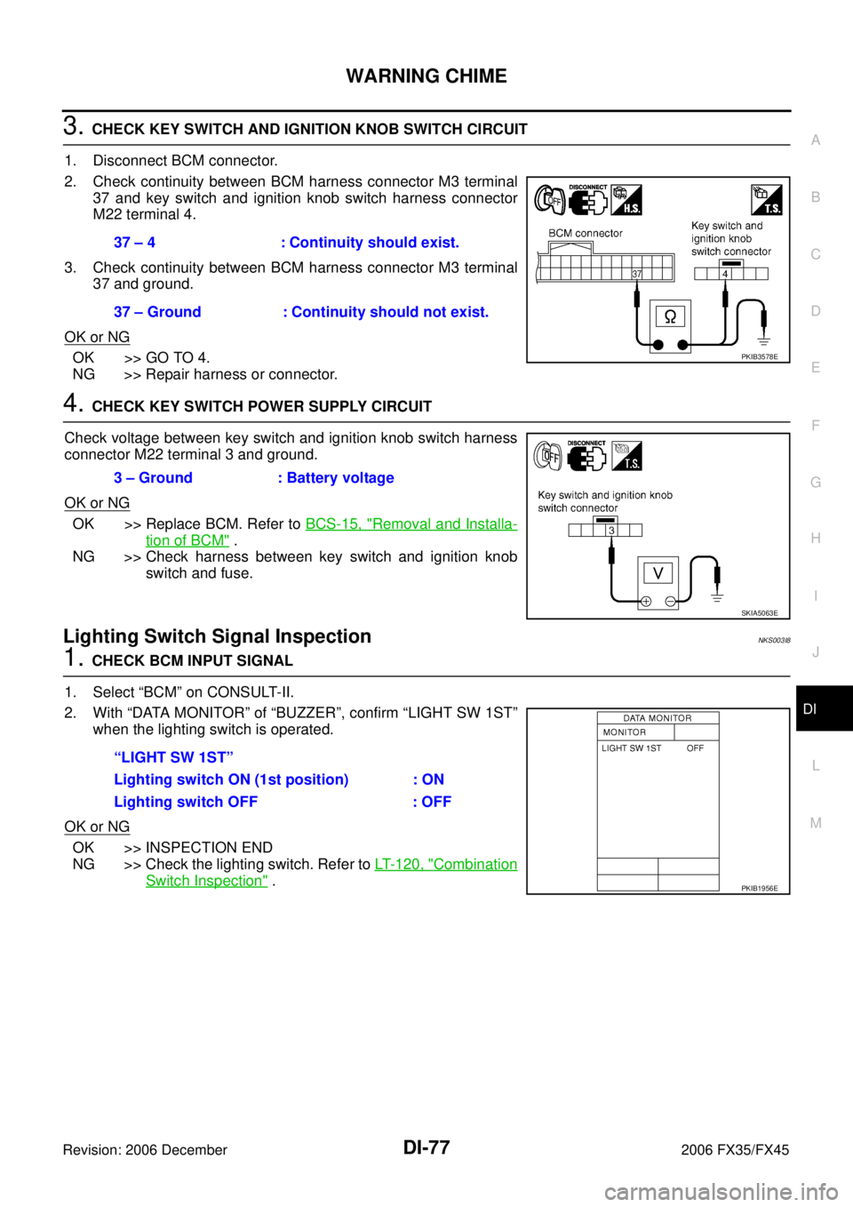
2. Check continuity between BCM harness connector M3 terminal 37 and key switch and ignition knob switch harness connector
M22 terminal 4.
3. Check continuity between BCM harness connector M3 terminal 37 and ground.
OK or NG
OK >> GO TO 4.
NG >> Repair harness or connector.
4. CHECK KEY SWITCH POWER SUPPLY CIRCUIT
Check voltage between key switch and ignition knob switch harness
connector M22 terminal 3 and ground.
OK or NG
OK >> Replace BCM. Refer to BCS-15, "Removal and Installa-
tion of BCM" .
NG >> Check harness between key switch and ignition knob
switch and fuse.
Lighting Switch Signal InspectionNKS003I8
1. CHECK BCM INPUT SIGNAL
1. Select “BCM” on CONSULT-II.
2. With “DATA MONITOR” of “BUZZER”, confirm “LIGHT SW 1ST” when the lighting switch is operated.
OK or NG
OK >> INSPECTION END
NG >> Check the lighting switch. Refer to LT- 1 2 0 , "
Combination
Switch Inspection" .
37 – 4 : Continuity should exist.
37 – Ground : Continuity should not exist.
PKIB3578E
3 – Ground : Battery voltage
SKIA5063E
“LIGHT SW 1ST”
Lighting switch ON (1st position) : ON
Lighting switch OFF : OFF
PKIB1956E
Page 1336 of 4462
DI-86
LANE DEPARTURE WARNING SYSTEM
Revision: 2006 December 2006 FX35/FX45
7. Mark point at the center of the point “E” and “F”, on the line “FW”.
CAUTION:
Make sure that “E” through “X” is equal to “F” through “X”.
8. Position the center of the right target to the point of “X”.
VEHICLE HEIGHT CHECK
Measure the wheel arch height. And calculate “Dh”.
NOTE:
“Dh” may be calculated as a minus value.
AIMING ADJUSTMENT
Operation Procedure
CAUTION:
�Perform the adjustment under unloaded vehicle condition.
�LDW indicator is turned off after the removal/installation, and blinks after replacement.
1. With the ignition switch OFF, connect CONSULT-II and CON- SULT-II CONVERTER to the data link connector, and then turn
ignition switch ON.
2. Start the engine, wait for at least 10 seconds, and touch “START (NISSAN BASED VHCL)”.
PKIB5331E
Dh [mm] = (Hfl + Hfr) ÷ 2 − 840
where, Hfl: Front left wheel arch height [mm]
Hfr: Front right wheel arch height [mm]
SKIB3164E
PBIB1503E
BCIA0029E
Page 1357 of 4462
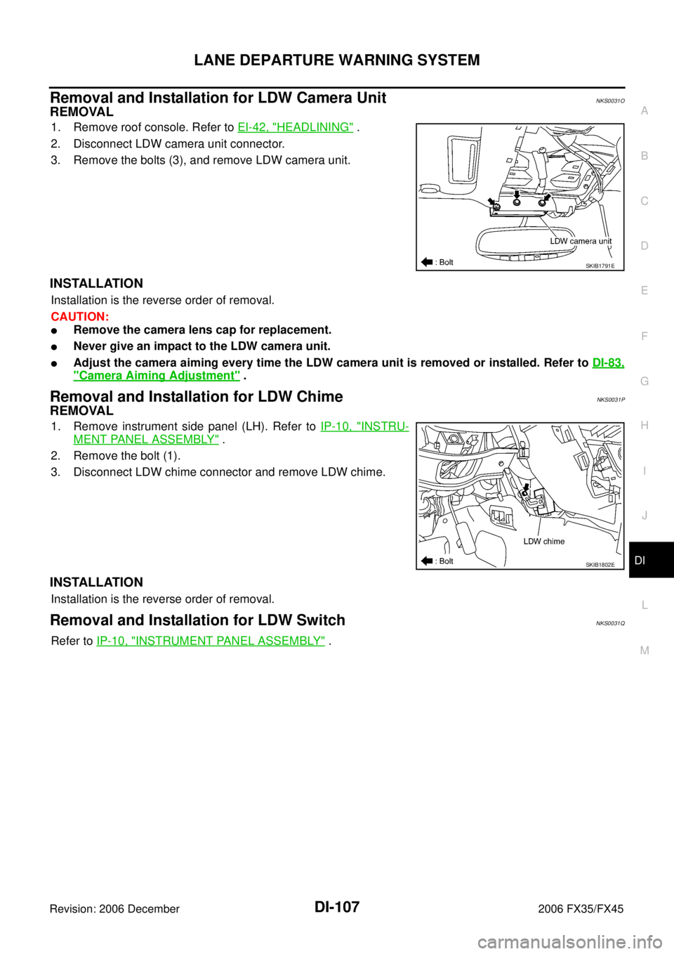
LANE DEPARTURE WARNING SYSTEM DI-107
C
D E
F
G H
I
J
L
M A
B
DI
Revision: 2006 December 2006 FX35/FX45
Removal and Installation for LDW Camera UnitNKS0031O
REMOVAL
1. Remove roof console. Refer to EI-42, "HEADLINING" .
2. Disconnect LDW camera unit connector.
3. Remove the bolts (3), and remove LDW camera unit.
INSTALLATION
Installation is the reverse order of removal.
CAUTION:
�Remove the camera lens cap for replacement.
�Never give an impact to the LDW camera unit.
�Adjust the camera aiming every time the LDW camera unit is removed or installed. Refer to DI-83,
"Camera Aiming Adjustment" .
Removal and Installation for LDW ChimeNKS0031P
REMOVAL
1. Remove instrument side panel (LH). Refer to IP-10, "INSTRU-
MENT PANEL ASSEMBLY" .
2. Remove the bolt (1).
3. Disconnect LDW chime connector and remove LDW chime.
INSTALLATION
Installation is the reverse order of removal.
Removal and Installation for LDW SwitchNKS0031Q
Refer to IP-10, "INSTRUMENT PANEL ASSEMBLY" .
SKIB1791E
SKIB1802E
Page 1363 of 4462
COMPASS DI-113
C
D E
F
G H
I
J
L
M A
B
DI
Revision: 2006 December 2006 FX35/FX45
Removal and Installation of CompassNKS003HW
Refer to GW-66, "Removal and Installation" .
Page 1365 of 4462
CLOCK DI-115
C
D E
F
G H
I
J
L
M A
B
DI
Revision: 2006 December 2006 FX35/FX45
Removal and Installation of ClockNKS0031S
REMOVAL
1. Remove A/T selecter lever knob. Refer to IP-12, "(D) A/T Select Lever Knob" .
2. Remove A/T console finisher. Refer to IP-12, "
(F) A/T Console Finisher" .
3. Remove instrument clock finisher. Refer to IP-12, "
(E) Instrument Clock Finisher" .
4. Remove tabs (A), and remove clock (1) from instrument clock finisher (2).
INSTALLATION
Installation is the reverse order of removal.
SKIB8488E