Page 1275 of 4462
COMBINATION METERS DI-25
C
D E
F
G H
I
J
L
M A
B
DI
Revision: 2006 December 2006 FX35/FX45
Fuel Level Sensor Unit and Pump (Main) Harness
Check continuity at following terminals.
�If the results of check are NG, replace fuel pump assembly. If the
results of check are OK, replace fuel level sensor unit.
Fuel Level Sensor Unit (Sub)
Check resistance between terminals 1 and 2.
*1 and *2: When float rod is in contact with stopper.
Removal and Installation of Combination MeterNKS003IC
Refer to IP-10, "INSTRUMENT PANEL ASSEMBLY" .
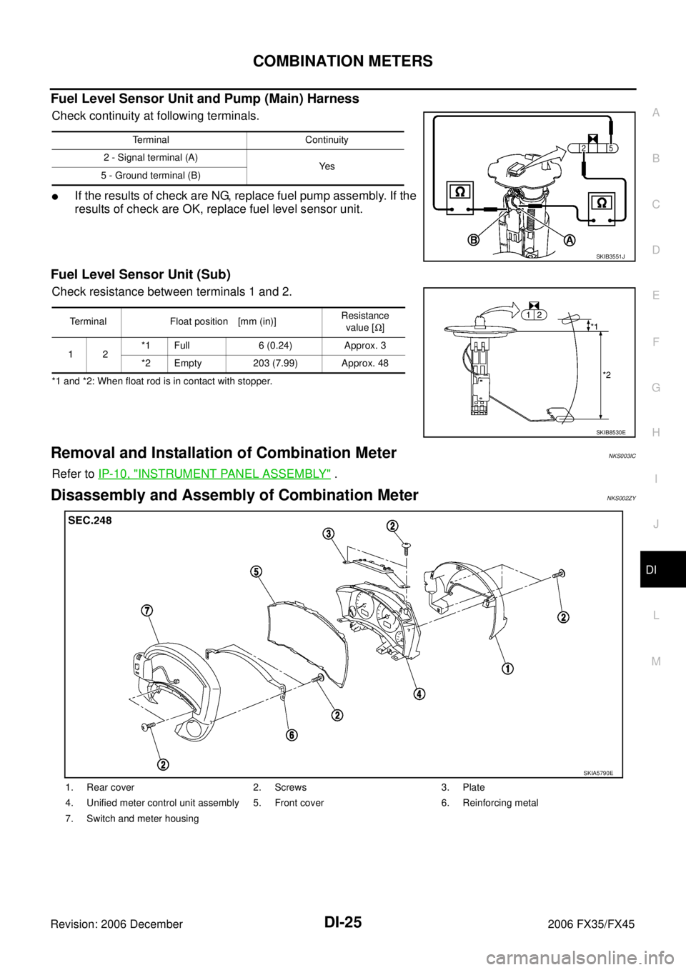
Disassembly and Assembly of Combination MeterNKS002ZY
Terminal Continuity
2 - Signal terminal (A) Ye s
5 - Ground terminal (B)
SKIB3551J
Terminal Float position [mm (in)] Resistance
value [ Ω]
12 *1 Full 6 (0.24) Approx. 3
*2 Empty 203 (7.99) Approx. 48
SKIB8530E
1. Rear cover 2. Screws 3. Plate
4. Unified meter control unit assembly 5. Front cover 6. Reinforcing metal
7. Switch and meter housing
SKIA5790E
Page 1277 of 4462
COMBINATION METERS DI-27
C
D E
F
G H
I
J
L
M A
B
DI
Revision: 2006 December 2006 FX35/FX45
6. Remove screws (A) and remove plate (1).
7. Disengage tabs (A) to separate front cover (1).
ASSEMBLY
Assembly is the reverse order of disassembly.
Removal and Installation of Odo/Trip Meter and Illumination Control SwitchNKS002ZZ
REMOVAL
1. Remove combination meter. Refer to IP-10, "INSTRUMENT PANEL ASSEMBLY" .
2. Remove switch and meter housing. Refer to DI-25, "
Disassembly and Assembly of Combination Meter" .
3. Remove screws (2), and remove switch assembly.
4. Remove screws (5), and remove odo/trip meter and illumination control switch.
INSTALLATION
Installation is the reverse order of removal.
SKIB8481E
SKIB8482E
SKIA5795E
SKIA5796E
Page 1285 of 4462

UNIFIED METER AND A/C AMP DI-35
C
D E
F
G H
I
J
L
M A
B
DI
Revision: 2006 December 2006 FX35/FX45
2. CHECK METER/GAUGES VISUALLY
Check the pointer on the meter/gauge fluctuate at the engine start.
Is the fluctuation acceptable?
YES >> GO TO 3.
NO >> GO TO 6.
3. CHECK CONTINUITY COMMUNICATION CIRCUIT (TX: COMBINATION METER)
1. Turn ignition switch OFF.
2. Disconnect combination meter connector and unified meter and A/C amp. connector.
3. Check continuity between combination meter harness connector M20 terminal 13 and unified meter and A/C amp. harness con-
nector M55 terminal 19.
4. Check continuity between combination meter harness connector M20 terminal 13 and ground.
OK or NG
OK >> GO TO 4.
NG >> Repair harness or connector.
4. CHECK VOLTAGE OF UNIFIED METER AND A/C AMP.
1. Connect unified meter and A/C amp. connector.
2. Turn ignition switch ON.
3. Check voltage between combination meter harness connector M20 terminal 13 and ground.
OK or NG
OK >> GO TO 5.
NG >> Replace unified meter and A/C amp. Refer to DI-37,
"Removal and Installation of Unified Meter and A/C
Amp."
13 – 19 : Continuity should exist.
13 – Ground : Continuity should not exist.
SKIA4837E
13 – Ground : Approx. 5 V
SKIA4886E
Page 1286 of 4462

DI-36
UNIFIED METER AND A/C AMP
Revision: 2006 December 2006 FX35/FX45
5. CHECK VOLTAGE SIGNAL OF COMBINATION METER
1. Turn ignition switch OFF.
2. Connect combination meter connector.
3. Turn ignition switch ON.
4. Check voltage signal between combination meter harness con- nector M20 terminal 13 and ground.
OK or NG
OK >> Replace unified meter and A/C amp. Refer to DI-37,
"Removal and Installation of Unified Meter and A/C Amp." .
NG >> Replace combination meter.
6. CHECK CONTINUITY COMMUNICATION CIRCUIT (RX: COMBINATION METER)
1. Turn ignition switch OFF.
2. Disconnect combination meter connector and unified meter and A/C amp. connector.
3. Check continuity between combination meter harness connector M20 terminal 14 and unified meter and A/C amp. harness con-
nector M55 terminal 9.
4. Check continuity between combination meter harness connector M20 terminal 14 and ground.
OK or NG
OK >> GO TO 7.
NG >> Repair harness or connector.
7. CHECK VOLTAGE OF COMBINATION METER
1. Connect combination meter connector.
2. Turn ignition switch ON.
3. Check voltage between unified meter and A/C amp. harness connector M55 terminal 9 and ground.
OK or NG
OK >> GO TO 8.
NG >> Replace combination meter. 13 – Ground:
SKIA9258E
SKIA3361E
14 – 9 : Continuity should exist.
14 – Ground : Continuity should not exist.
SKIA4836E
9 – Ground : Approx. 5 V
PKIB3587E
Page 1287 of 4462

UNIFIED METER AND A/C AMP DI-37
C
D E
F
G H
I
J
L
M A
B
DI
Revision: 2006 December 2006 FX35/FX45
8. CHECK VOLTAGE SIGNAL OF UNIFIED METER AND A/C AMP.
1. Turn ignition switch OFF.
2. Connect unified meter and A/C amp. connector.
3. Turn ignition switch ON.
4. Check voltage signal between combination meter harness con- nector M20 terminal 14 and ground.
OK or NG
OK >> Replace combination meter.
NG >> Replace unified meter and A/C amp. Refer to DI-37, "
Removal and Installation of Unified Meter
and A/C Amp." .
DTC [B2205] Vehicle Speed CircuitNKS00307
Symptom: Display “VEHICLE SPEED CIRC [B2205]” at the result of self-diagnosis for unified meter and A/C
amp.
Perform self-diagnosis of ABS actuator and electric unit (control unit), and repair or replace malfunctioning
parts. Refer to BRC-24, "
CONSULT-II Functions (VDC)" .
Removal and Installation of Unified Meter and A/C Amp. NKS00308
REMOVAL
1. Remove the audio unit (1). Refer to AV- 4 3 , "Removal and Instal-
lation of Audio Unit" .
2. Remove the screws (A).
3. Remove the screws (B) and remove the unified meter and A/C amp. (2).
INSTALLATION
Installation is the reverse order of removal.
NOTE:
Use appropriate screws for each, as screws for audio unit and display unit are different from that for unified
meter and A/C amp. 14 – Ground:
SKIA9260E
SKIA3362E
SKIB8483E
Page 1298 of 4462
NKS0030E
1. CHECK OIL PRESSURE WARNING LAMP OPERATION
Activate IPDM E/R auto active")
DI-48
WARNING LAMPS
Revision: 2006 December 2006 FX35/FX45
Oil Pressure Warning Lamp Stays Off (Ignition Switch ON)NKS0030E
1. CHECK OIL PRESSURE WARNING LAMP OPERATION
Activate IPDM E/R auto active test. Refer to PG-21, "
Auto Active Test" .
Does oil pressure warning lamp blink?
YES >> GO TO 2.
NO >> GO TO 5.
2. CHECK IPDM E/R INPUT SIGNAL
1. Turn ignition switch ON.
2. Check voltage between IPDM E/R harness connector E9 termi- nal 57 and ground.
OK or NG
OK >> Replace IPDM E/R. Refer to PG-28, "Removal and
Installation of IPDM E/R" .
NG >> GO TO 3.
3. CHECK OIL PRESSURE SWITCH
1. Turn ignition switch OFF.
2. Disconnect oil pressure switch connector.
3. Check oil pressure switch. Refer to DI-51, "
OIL PRESSURE SWITCH" .
OK or NG
OK >> GO TO 4.
NG >> Replace oil pressure switch.
4. CHECK OIL PRESSURE SWITCH CIRCUIT
1. Disconnect IPDM E/R connector.
2. Check continuity between IPDM E/R harness connector E9 ter- minal 57 and oil pressure switch harness connector F1 terminal
1.
OK or NG
OK >> Replace IPDM E/R. Refer to PG-28, "Removal and
Installation of IPDM E/R" .
NG >> Repair harness or connector.
5. CHECK UNIFIED METER AND A/C AMP. (CONSULT-II)
Perform self-diagnosis of unified meter and A/C amp. Refer to DI-31, "
CONSULT-II Function (METER A/C
AMP)" .
Self-diagnosis results
No malfunction detected >> GO TO 6.
Malfunction detected >> Check applicable parts, and repair or replace corresponding parts. 57 – Ground : Approx. 0 V
SKIB6449E
57 – 1 : Continuity should exist.
PKIB3572E
Page 1299 of 4462

WARNING LAMPS DI-49
C
D E
F
G H
I
J
L
M A
B
DI
Revision: 2006 December 2006 FX35/FX45
6. CHECK UNIFIED METER AND A/C AMP. INPUT SIGNAL
1. Select “METER A/C AMP” on CONSULT-II.
2. Operate ignition switch with “OIL W/L” of “DATA MONITOR” and check operation status.
OK or NG
OK >> Replace combination meter.
NG >> GO TO 7.
7. CHECK BCM INPUT SIGNAL
1. Select “BCM” on CONSULT-II.
2. Select “DATA MONITOR” of “SIGNAL BUFFER”.
3. Operate ignition switch with “OIL PRESS SW” of “DATA MONI- TOR” and check operate status.
OK or NG
OK >> Replace BCM. Refer to BCS-15, "Removal and Installa-
tion of BCM" .
NG >> Replace IPDM E/R. Refer to PG-28, "
Removal and
Installation of IPDM E/R" .
Oil Pressure Warning Lamp Does Not Turn Off (Oil Pressure Is Normal)NKS0030F
NOTE:
For oil pressure inspection, refer to LU-8, "
OIL PRESSURE CHECK" (VQ35DE) or LU-25, "OIL PRESSURE
CHECK" (VK45DE)
1. CHECK OIL PRESSURE WARNING LAMP OPERATION
Activate IPDM E/R auto active test. Refer to PG-21, "
Auto Active Test" .
Does oil pressure warning lamp blink?
YES >> GO TO 2.
NO >> GO TO 5. “OIL W/L”
When ignition switch is in ON
position (Engine stopped) : ON
When engine running : OFF
PKIA2064E
“OIL PRESS SW”
When ignition switch is in ON
position (Engine stopped) : ON
When engine running : OFF
SKIA8709E
Page 1300 of 4462

DI-50
WARNING LAMPS
Revision: 2006 December 2006 FX35/FX45
2. CHECK IPDM E/R OUTPUT SIGNAL
1. Turn ignition switch OFF.
2. Disconnect oil pressure switch connector.
3. Turn ignition switch ON.
4. Check voltage between oil pressure switch harness connector F1 terminal 1 and ground.
OK or NG
OK >> GO TO 3.
NG >> GO TO 4.
3. CHECK OIL PRESSURE SWITCH
1. Turn ignition switch OFF.
2. Check oil pressure switch. Refer to DI-51, "
OIL PRESSURE SWITCH" .
OK or NG
OK >> Replace IPDM E/R. Refer to PG-28, "Removal and Installation of IPDM E/R" .
NG >> Replace oil pressure switch.
4. CHECK OIL PRESSURE SWITCH CIRCUIT
1. Turn ignition switch OFF.
2. Disconnect IPDM E/R connector.
3. Check continuity between IPDM E/R harness connector E9 ter- minal 57 and ground.
OK or NG
OK >> Replace IPDM E/R. Refer to PG-28, "Removal and
Installation of IPDM E/R" .
NG >> Repair harness or connector.
5. CHECK IPDM E/R (CONSULT-II)
Perform self-diagnosis of IPDM E/R. Refer to PG-19, "
CONSULT-II Function (IPDM E/R)" .
Self-diagnosis results
No malfunction detected >> Replace combination meter.
Malfunction detected >> Check applicable parts, and repair or replace corresponding parts. 1 – Ground : Approx. 12 V
PKIB3573E
57 – Ground : Continuity should not exist.
SKIA5013E
 and remove plate (1).
7. Disengage tabs (A) to separate front cover (1).
AS")