Page 3073 of 4462
![INFINITI FX35 2006 Service Manual SERVICE DATA AND SPECIFICATIONS (SDS) EM-279
[VK45DE]
C
D E
F
G H
I
J
K L
M A
EM
Revision: 2006 December 2006 FX35/FX45
Valve Dimensions
Unit: mm (in)
Valve Guide
Unit: mm (in)
Items
Sta](/manual-img/42/57019/w960_57019-3072.png "INFINITI FX35 2006 Service Manual SERVICE DATA AND SPECIFICATIONS (SDS) EM-279
[VK45DE]
C
D E
F
G H
I
J
K L
M A
EM
Revision: 2006 December 2006 FX35/FX45
Valve Dimensions
Unit: mm (in)
Valve Guide
Unit: mm (in)
Items
Sta")
SERVICE DATA AND SPECIFICATIONS (SDS) EM-279
[VK45DE]
C
D E
F
G H
I
J
K L
M A
EM
Revision: 2006 December 2006 FX35/FX45
Valve Dimensions
Unit: mm (in)
Valve Guide
Unit: mm (in)
Items
Standard
Valve head diameter “D” Intake 36.0 - 36.3 (1.417 - 1.429) Exhaust 31.2 - 31.5 (1.228 - 1.240)
Valve length “L” Intake 96.57 (3.8020)
Exhaust 94.50 (3.720)
Valve stem diameter “d” Intake 5.972 - 5.980 (0.2351 - 0.2354)
Exhaust 5.962 - 5.970 (0.2347 - 0.2350)
Valve seat angle “ α” Intake
45 °15 ′ - 45 °45 ′
Exhaust
Valve margin “T” Intake 1.15 - 1.45 (0.0453 - 0.0571)
Exhaust 1.85 - 2.15 (0.0728 - 0.0846)
SEM188
Items Standard Oversize (Service) [0.2 (0.008)]
Valve guide Outer diameter
10.023 - 10.034 (0.3946 -
0.3950) 10.223 - 10.234 (0.4025 -
0.4029)
Inner diameter (Finished size) 6.000 - 6.018 (0.2362 - 0.2369)
Cylinder head valve guide hole diameter 9.975 - 9.996 (0.3927 - 0.3935) 10.175 - 10.196 (0.4006 -
0.4014)
Interference fit of valve guide 0.027 - 0.059 (0.0011 - 0.0023)
Items Standard Limit
Valve guide clearance Intake 0.020 - 0.046 (0.0008 - 0.0018) 0.08 (0.003)
Exhaust 0.030 - 0.056 (0.0012 - 0.0022) 0.1 (0.004)
Projection length “L” Intake 10.1 - 10.3 (0.398 - 0.406) —
Exhaust 10.0 - 10.4 (0.394 - 0.409) —
PBIC0184E
Page 3074 of 4462
EM-280
[VK45DE]
SERVICE DATA AND SPECIFICATIONS (SDS)
Revision: 2006 December 2006 FX35/FX45
Valve Seat
Unit: mm (in)
Valve Spring
Items Standard Service
Cylinder head seat recess diameter “D” Intake 37.000 - 37.016 (1.4567 - 1.4573) 37.500 - 37.516 (1.4764 - 1.4770)
Exhaust 32.200 - 32.216 (1.2677 - 1.2683) 32.700 - 32.716 (1.2874 - 1.2880)
Valve seat interference fit Intake 0.081 - 0.113 (0.0032 - 0.0044)
Exhaust 0.064 - 0.096 (0.0025 - 0.0038)
Valve seat outer diameter “d” Intake 37.097 - 37.113 (1.4605 - 1.4611) 37.597 - 37.613 (1.4802 - 1.4808)
Exhaust 32.280 - 32.296 (1.2709 - 1.2715) 32.780 - 32.796 (1.2905 - 1.2912)
PBIC2379E
Free height mm (in) 46.35 - 46.85 (1.8247 - 1.8444)
Pressure N (kg, lb) at height mm (in) Installation 165 - 189 (16.8 - 19.3, 37 - 42) at 33.8 (1.331)
Valve open 290 - 330 (29.6 - 33.7, 65 - 74) at 24.4 (0.961)
Out-of-square mm (in) Limit 2.0 (0.079)
Page 3083 of 4462
EX-1
EXHAUST SYSTEM
B ENGINE
CONTENTS
C
D E
F
G H
I
J
K L
M
SECTION EX
A
EX
Revision: 2006 December 2006 FX35/FX45
EXHAUST SYSTEM
PREPARATION ...................................................... ..... 2
Commercial Service Tools ................................... ..... 2
EXHAUST SYSTEM .............................................. ..... 3
Checking Exhaust System .................................. ..... 3 Components ........................................................
..... 3
Removal and Installation ..................................... ..... 4
REMOVAL ........................................................ ..... 4
INSTALLATION ................................................ ..... 4
INSPECTION AFTER INSTALLATION ............. ..... 5
Page 3085 of 4462
EXHAUST SYSTEM EX-3
C
D E
F
G H
I
J
K L
M A
EX
Revision: 2006 December 2006 FX35/FX45
EXHAUST SYSTEMPFP:20100
Checking Exhaust SystemNBS004IN
Check exhaust pipes, muffler and mounting for improper attachment,
leaks, cracks, damage or deterioration.
�If anything is found, repair or replace damaged parts.
ComponentsNBS004IO
CAUTION:
�Be sure to use genuine exhaust system parts or equivalents which are specially designed for heat
resistance, corrosion resistance, and shape.
�Perform the operation with the exhaust system fully cooled down because the system will be hot
just after engine stops.
�Be careful not to cut your hand on the heat insulator edge.
VQ35DE
SMA211A
PBIC1583E
1. Main muffler 2. Mounting rubber 3. Main muffler mounting bracket
4. Mounting rubber 5. Center muffler 6. Gasket
7. Exhaust front tube 8. Gasket 9. Collar
Page 3086 of 4462
EX-4
EXHAUST SYSTEM
Revision: 2006 December 2006 FX35/FX45
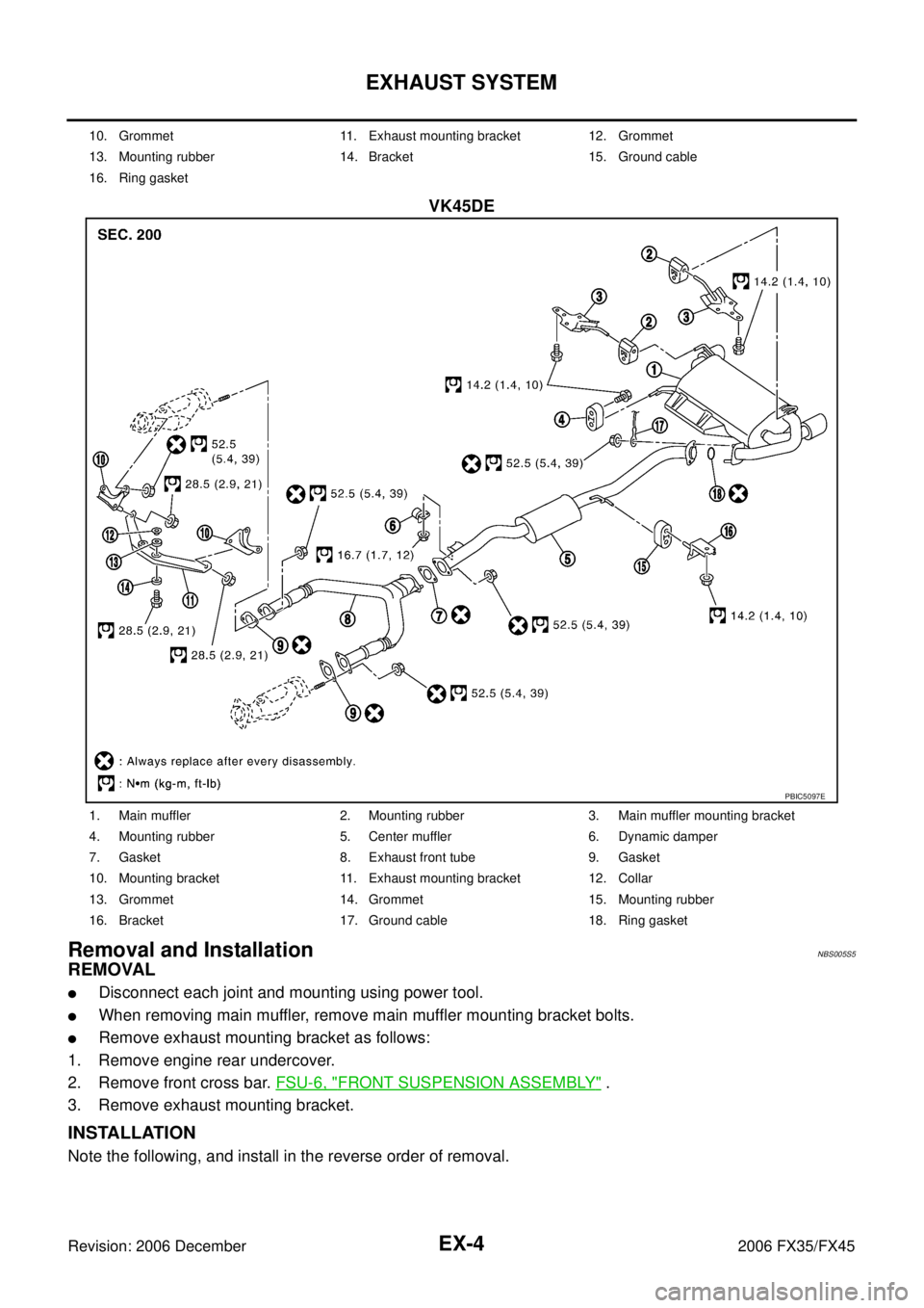
VK45DE
Removal and InstallationNBS005S5
REMOVAL
�Disconnect each joint and mounting using power tool.
�When removing main muffler, remove main muffler mounting bracket bolts.
�Remove exhaust mounting bracket as follows:
1. Remove engine rear undercover.
2. Remove front cross bar. FSU-6, "
FRONT SUSPENSION ASSEMBLY" .
3. Remove exhaust mounting bracket.
INSTALLATION
Note the following, and install in the reverse order of removal.
10. Grommet 11. Exhaust mounting bracket 12. Grommet
13. Mounting rubber 14. Bracket 15. Ground cable
16. Ring gasket
PBIC5097E
1. Main muffler 2. Mounting rubber 3. Main muffler mounting bracket
4. Mounting rubber 5. Center muffler 6. Dynamic damper
7. Gasket 8. Exhaust front tube 9. Gasket
10. Mounting bracket 11. Exhaust mounting bracket 12. Collar
13. Grommet 14. Grommet 15. Mounting rubber
16. Bracket 17. Ground cable 18. Ring gasket
Page 3087 of 4462

EXHAUST SYSTEM EX-5
C
D E
F
G H
I
J
K L
M A
EX
Revision: 2006 December 2006 FX35/FX45
�Tighten main muffler mounting bracket bolts in numerical order
as shown in the figure.
CAUTION:
�Always replace exhaust tube gaskets with new ones when reassembling.
�If heat insulator is badly deformed, repair or replace it. If deposits such as mud pile up on the heat
insulator, remove them.
�When installing heat insulator avoid large gaps or interference between heat insulator and each
exhaust pipe.
�Remove deposits from the sealing surface of each connection. Connect them securely to avoid
gases leakage.
�Temporarily tighten mounting nuts on the exhaust manifold side and mounting bolts on the vehi-
cle side. Check each part for unusual interference, and then tighten them to the specified torque.
�When installing each mounting rubber, avoid twisting or unusual extension in up/down and right/
left directions.
INSPECTION AFTER INSTALLATION
�Make sure clearance between tail tube and bumper is even.
�With engine running, check exhaust tube joints for gas leakage and unusual noises.
�Check to ensure that mounting brackets and mounting rubbers are installed properly and free from undue
stress. Improper installation could result in excessive noise and vibration.
PBIC1049E
Page 3088 of 4462
EX-6
EXHAUST SYSTEM
Revision: 2006 December 2006 FX35/FX45
Page 3127 of 4462
NDS000BC
COM")
FRONT FINAL DRIVE ASSEMBLY FFD-13
C E F
G H
I
J
K L
M A
B
FFD
Revision: 2006 December 2006 FX35/FX45
FRONT FINAL DRIVE ASSEMBLYPFP:38500
Removal and Installation (VQ35DE Models)NDS000BC
COMPONENTS
REMOVAL
1. Remove three engine mounting bracket upper bolts. Refer to EM-118, "Components (AWD Models)" .
2. Remove three way catalyst (right bank). Refer to EM-26, "
EXHAUST MANIFOLD AND THREE WAY CAT-
ALYST" .
3. Remove stabilizer assembly with power tool. Refer to FSU-16, "
STABILIZER BAR" .
4. Remove steering gearbox mounting bolts with power tool. Refer to PS-17, "
POWER STEERING GEAR
AND LINKAGE" .
5. Remove front drive shaft both. Refer to FA X - 1 2 , "
FRONT DRIVE SHAFT" .
6. Remove side shaft assembly.
7. Remove front propeller shaft. Refer to PR-4, "
FRONT PROPELLER SHAFT" .
8. Remove front suspension member with power tool. Refer to FSU-17, "
FRONT SUSPENSION MEMBER" .
9. Remove breather hose and tube.
10. Remove mounting bolts and remove front final drive assembly from the vehicle.
INSTALLATION
Note the following, and installation is in the reverse order of removal.
�Refer to FFD-13, "COMPONENTS" about each tightening torque.
�When installing the side shaft, apply multi-purpose grease to contact surface of side shaft and side shaft
oil seal.
1. Front final drive assembly 2. Side shaft 3. Bushing
4. Front propeller shaft 5. Breather hose 6. Breather tube
7. Breather connector 8. Engine mounting bracket 9. Insulator
Refer to GI-11, "
Components" , for the symbols in the figure.
PDIA0789J
![INFINITI FX35 2006 Service Manual EM-280
[VK45DE]
SERVICE DATA AND SPECIFICATIONS (SDS)
Revision: 2006 December 2006 FX35/FX45
Valve Seat
Unit: mm (in)
Valve Spring
Items Standard Service
Cylinder head seat recess diameter “D” I](/manual-img/42/57019/w960_57019-3073.png "INFINITI FX35 2006 Service Manual EM-280
[VK45DE]
SERVICE DATA AND SPECIFICATIONS (SDS)
Revision: 2006 December 2006 FX35/FX45
Valve Seat
Unit: mm (in)
Valve Spring
Items Standard Service
Cylinder head seat recess diameter “D” I")