Page 4439 of 4462

FRONT WIPER AND WASHER SYSTEM WW-37
C
D E
F
G H
I
J
L
M A
B
WW
Revision: 2006 December 2006 FX35/FX45
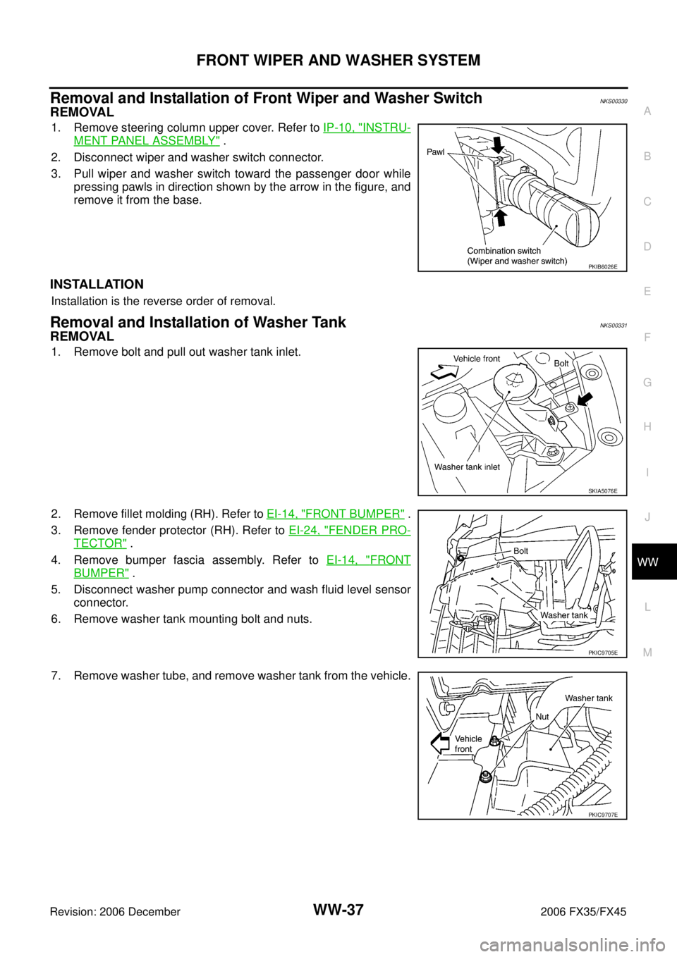
Removal and Installation of Front Wiper and Washer SwitchNKS00330
REMOVAL
1. Remove steering column upper cover. Refer to IP-10, "INSTRU-
MENT PANEL ASSEMBLY" .
2. Disconnect wiper and washer switch connector.
3. Pull wiper and washer switch toward the passenger door while pressing pawls in direction shown by the arrow in the figure, and
remove it from the base.
INSTALLATION
Installation is the reverse order of removal.
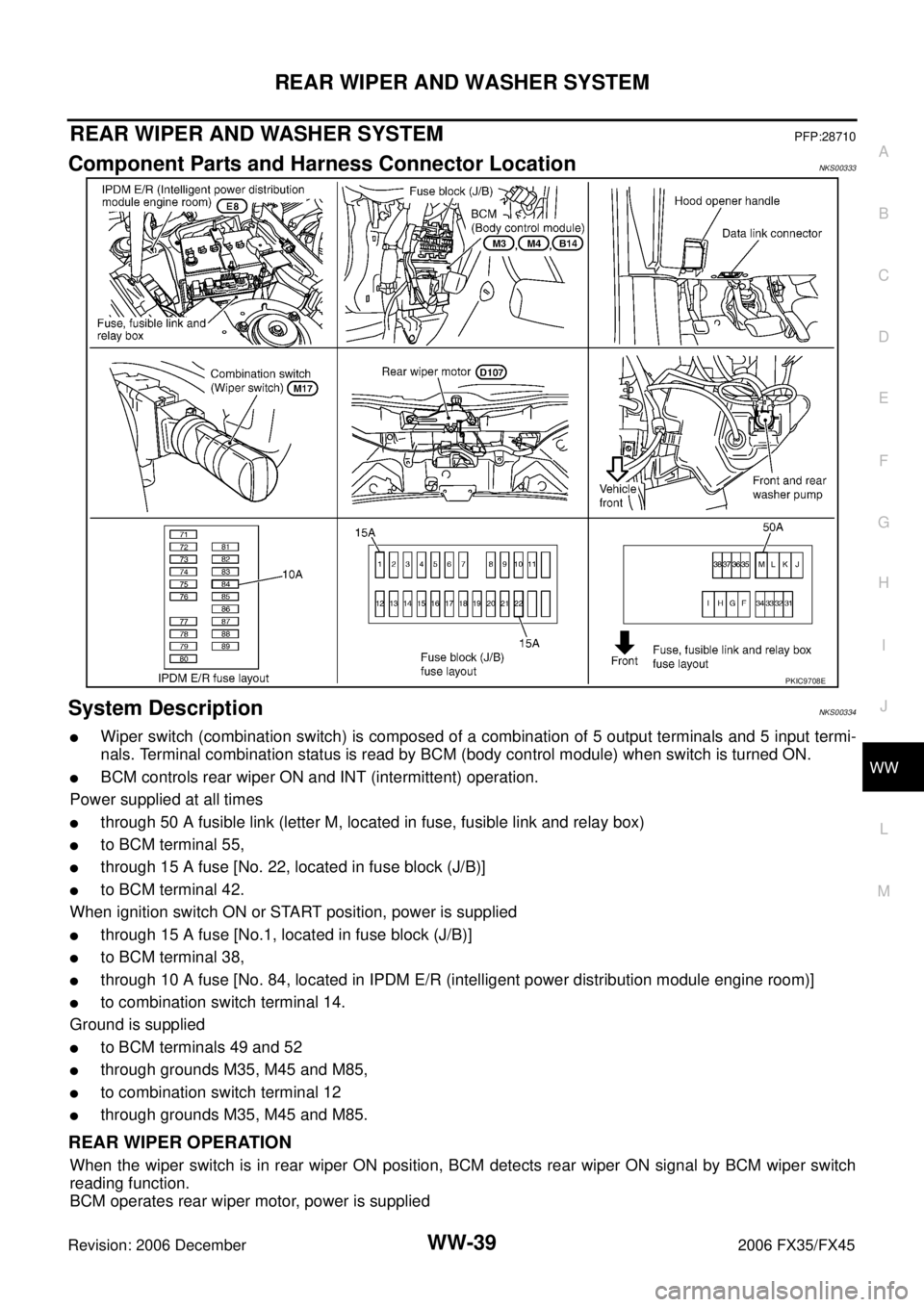
Removal and Installation of Washer TankNKS00331
REMOVAL
1. Remove bolt and pull out washer tank inlet.
2. Remove fillet molding (RH). Refer to EI-14, "
FRONT BUMPER" .
3. Remove fender protector (RH). Refer to EI-24, "
FENDER PRO-
TECTOR" .
4. Remove bumper fascia assembly. Refer to EI-14, "
FRONT
BUMPER" .
5. Disconnect washer pump connector and wash fluid level sensor connector.
6. Remove washer tank mounting bolt and nuts.
7. Remove washer tube, and remove washer tank from the vehicle.
PKIB6026E
SKIA5076E
PKIC9705E
PKIC9707E
Page 4440 of 4462
WW-38
FRONT WIPER AND WASHER SYSTEM
Revision: 2006 December 2006 FX35/FX45
INSTALLATION
Installation is the reverse order of removal.
NOTE:
After installation, add water up to the upper level of the washer tank inlet, and check for water leaks.
Removal and Installation of Washer PumpNKS00332
REMOVAL
1. Remove fillet molding (RH). Refer to EI-14, "FRONT BUMPER" .
2. Remove fender protector (RH). Refer to EI-24, "
FENDER PROTECTOR" .
3. Remove bumper fascia assembly. Refer to EI-14, "
FRONT BUMPER" .
4. Disconnect washer pump connector and tube.
5. Pull out washer pump in direction shown by the arrow in the fig- ure. Remove washer pump from washer tank.
INSTALLATION
Installation is the reverse order of removal.
NOTE:
When installing washer pump, there should be no packing twists, etc. Washer tank mounting bolt : 5.7 N·m (0.58 kg-m, 50 in-lb)
Washer tank mounting nut : 5.7 N·m (0.58 kg-m, 50 in-lb)
Washer tank inlet mounting bolt : 6.8 N·m (0.69 kg-m, 60 in-lb)
PKIC9706E
Page 4441 of 4462

REAR WIPER AND WASHER SYSTEM WW-39
C
D E
F
G H
I
J
L
M A
B
WW
Revision: 2006 December 2006 FX35/FX45
REAR WIPER AND WASHER SYSTEMPFP:28710
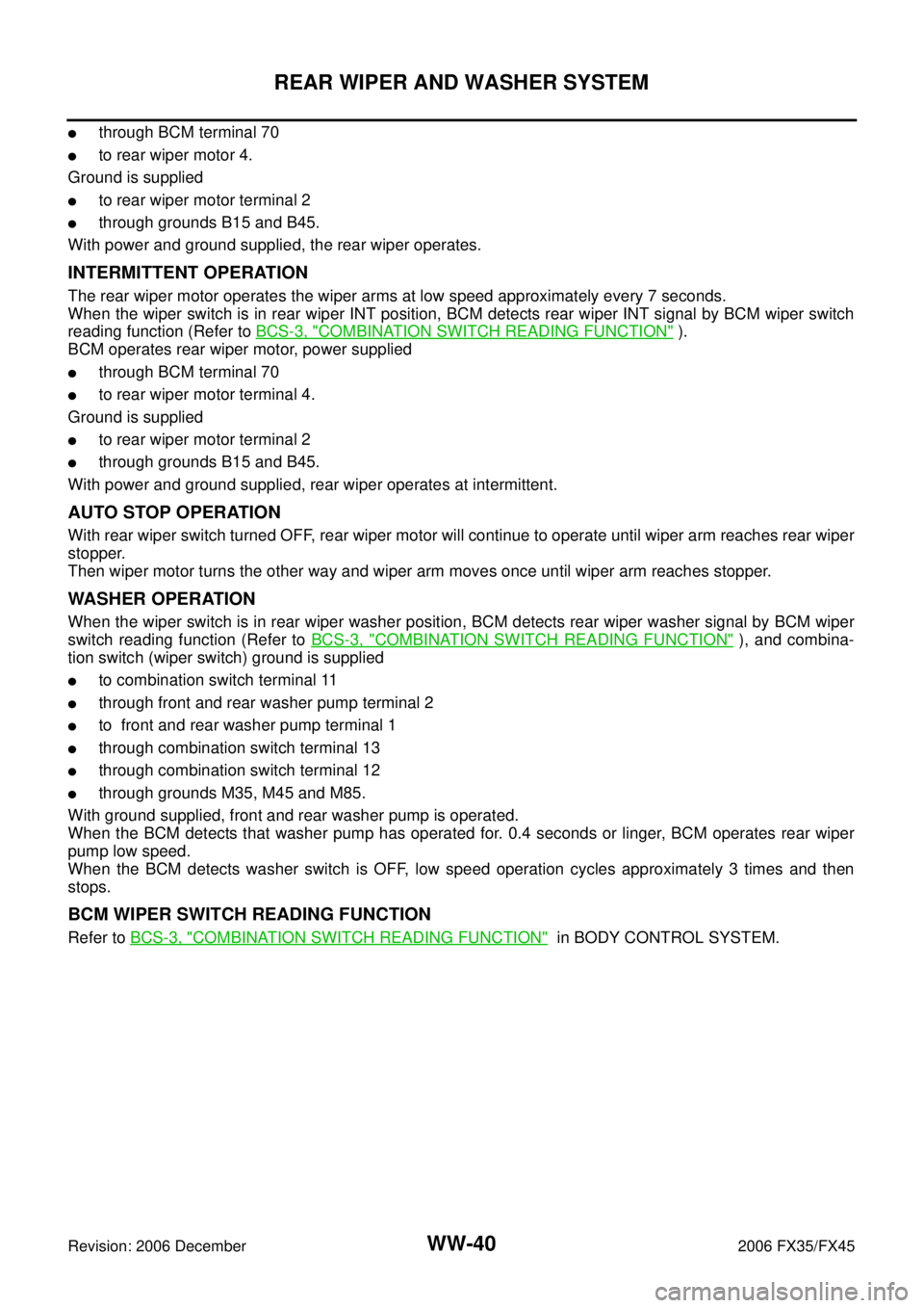
Component Parts and Harness Connector LocationNKS00333
System DescriptionNKS00334
�Wiper switch (combination switch) is composed of a combination of 5 output terminals and 5 input termi-
nals. Terminal combination status is read by BCM (body control module) when switch is turned ON.
�BCM controls rear wiper ON and INT (intermittent) operation.
Power supplied at all times
�through 50 A fusible link (letter M, located in fuse, fusible link and relay box)
�to BCM terminal 55,
�through 15 A fuse [No. 22, located in fuse block (J/B)]
�to BCM terminal 42.
When ignition switch ON or START position, power is supplied
�through 15 A fuse [No.1, located in fuse block (J/B)]
�to BCM terminal 38,
�through 10 A fuse [No. 84, located in IPDM E/R (intelligent power distribution module engine room)]
�to combination switch terminal 14.
Ground is supplied
�to BCM terminals 49 and 52
�through grounds M35, M45 and M85,
�to combination switch terminal 12
�through grounds M35, M45 and M85.
REAR WIPER OPERATION
When the wiper switch is in rear wiper ON position, BCM detects rear wiper ON signal by BCM wiper switch
reading function.
BCM operates rear wiper motor, power is supplied
PKIC9708E
Page 4442 of 4462

WW-40
REAR WIPER AND WASHER SYSTEM
Revision: 2006 December 2006 FX35/FX45
�through BCM terminal 70
�to rear wiper motor 4.
Ground is supplied
�to rear wiper motor terminal 2
�through grounds B15 and B45.
With power and ground supplied, the rear wiper operates.
INTERMITTENT OPERATION
The rear wiper motor operates the wiper arms at low speed approximately every 7 seconds.
When the wiper switch is in rear wiper INT position, BCM detects rear wiper INT signal by BCM wiper switch
reading function (Refer to BCS-3, "
COMBINATION SWITCH READING FUNCTION" ).
BCM operates rear wiper motor, power supplied
�through BCM terminal 70
�to rear wiper motor terminal 4.
Ground is supplied
�to rear wiper motor terminal 2
�through grounds B15 and B45.
With power and ground supplied, rear wiper operates at intermittent.
AUTO STOP OPERATION
With rear wiper switch turned OFF, rear wiper motor will continue to operate until wiper arm reaches rear wiper
stopper.
Then wiper motor turns the other way and wiper arm moves once until wiper arm reaches stopper.
WASHER OPERATION
When the wiper switch is in rear wiper washer position, BCM detects rear wiper washer signal by BCM wiper
switch reading function (Refer to BCS-3, "
COMBINATION SWITCH READING FUNCTION" ), and combina-
tion switch (wiper switch) ground is supplied
�to combination switch terminal 11
�through front and rear washer pump terminal 2
�to front and rear washer pump terminal 1
�through combination switch terminal 13
�through combination switch terminal 12
�through grounds M35, M45 and M85.
With ground supplied, front and rear washer pump is operated.
When the BCM detects that washer pump has operated for. 0.4 seconds or linger, BCM operates rear wiper
pump low speed.
When the BCM detects washer switch is OFF, low speed operation cycles approximately 3 times and then
stops.
BCM WIPER SWITCH READING FUNCTION
Refer to BCS-3, "COMBINATION SWITCH READING FUNCTION" in BODY CONTROL SYSTEM.
Page 4443 of 4462
REAR WIPER AND WASHER SYSTEM WW-41
C
D E
F
G H
I
J
L
M A
B
WW
Revision: 2006 December 2006 FX35/FX45
Wiring Diagram — WIP/ R —NKS00335
TKWM4376E
Page 4444 of 4462
WW-42
REAR WIPER AND WASHER SYSTEM
Revision: 2006 December 2006 FX35/FX45
TKWM4377E
Page 4445 of 4462

REAR WIPER AND WASHER SYSTEM WW-43
C
D E
F
G H
I
J
L
M A
B
WW
Revision: 2006 December 2006 FX35/FX45
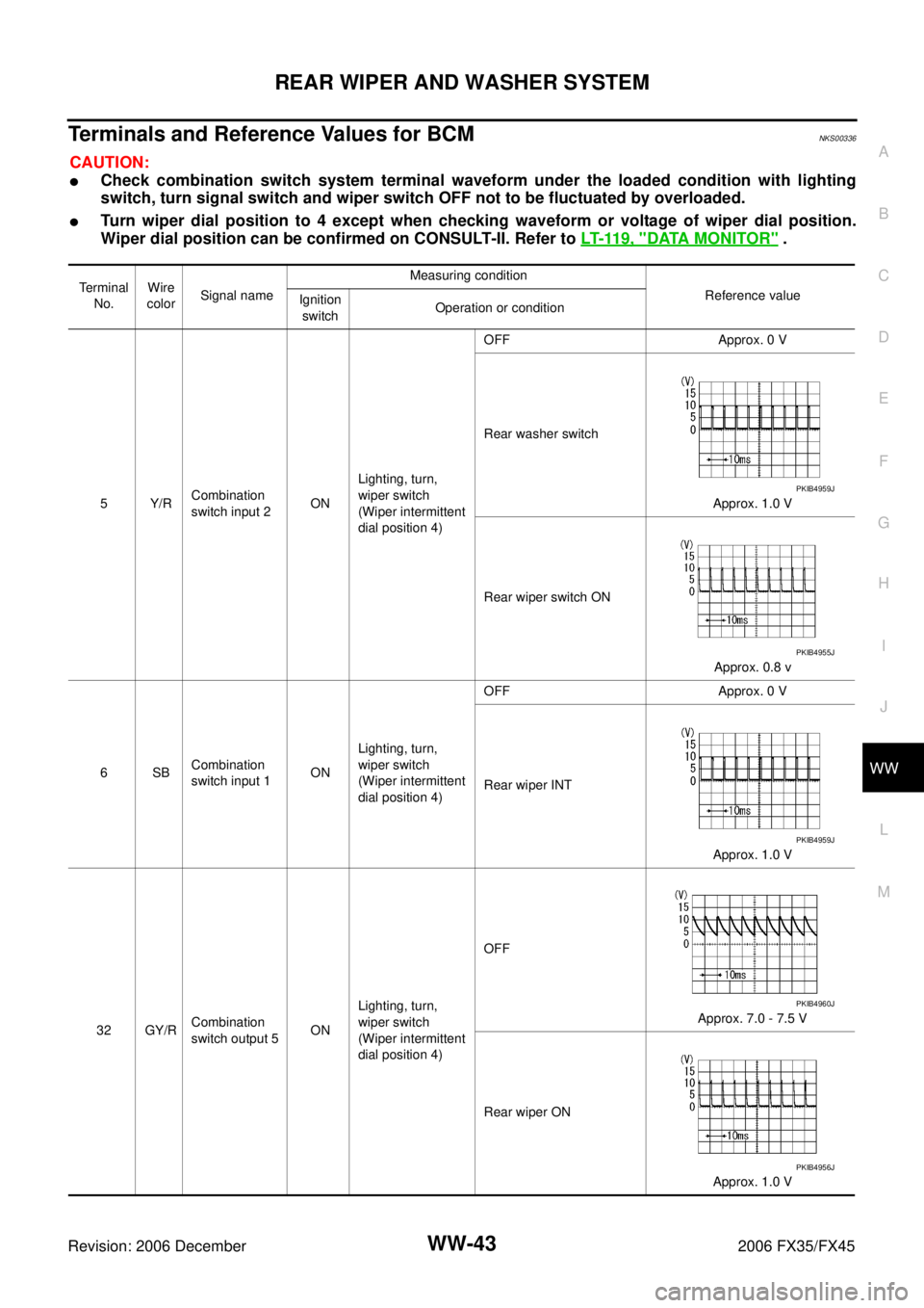
Terminals and Reference Values for BCMNKS00336
CAUTION:
�Check combination switch system terminal waveform under the loaded condition with lighting
switch, turn signal switch and wiper switch OFF not to be fluctuated by overloaded.
�Turn wiper dial position to 4 except when checking waveform or voltage of wiper dial position.
Wiper dial position can be confirmed on CONSULT-II. Refer to LT- 11 9 , "
DATA MONITOR" .
Terminal
No. Wire
color Signal name Measuring condition
Reference value
Ignition
switch Operation or condition
5Y/R Combination
switch input 2 ON Lighting, turn,
wiper switch
(Wiper intermittent
dial position 4) OFF Approx. 0 V
Rear washer switch Approx. 1.0 V
Rear wiper switch ON Approx. 0.8 v
6SB Combination
switch input 1 ON Lighting, turn,
wiper switch
(Wiper intermittent
dial position 4) OFF Approx. 0 V
Rear wiper INT Approx. 1.0 V
32 GY/R Combination
switch output 5 ON Lighting, turn,
wiper switch
(Wiper intermittent
dial position 4) OFF
Approx. 7.0 - 7.5 V
Rear wiper ON Approx. 1.0 V
PKIB4959J
PKIB4955J
PKIB4959J
PKIB4960J
PKIB4956J
Page 4446 of 4462
WW-44
REAR WIPER AND WASHER SYSTEM
Revision: 2006 December 2006 FX35/FX45
33 G Combination
switch output 4 ON Lighting, turn,
wiper switch
(Wiper intermittent
dial position 4) OFF
Approx. 7.2 V
Rear wiper switch INT Approx. 1.2 V
34 W/B Combination
switch output 3 ON Lighting, turn,
wiper switch
(Wiper intermittent
dial position 4) OFF
Approx. 7.2 V
Rear washer switch Approx. 1.2 V
38 W/L Ignition switch
(ON) ON — Battery voltage
39 L CAN − H— — —
40 P CAN − L— — —
42 L/R Battery power
supply OFF — Battery voltage
49 B Ground ON — Approx. 0 V
52 B Ground ON — Approx. 0 V
55 G Battery power
supply OFF — Battery voltage
59 Y Rear wiper
auto stop signal ON Wiper operating Approx. 0 V
Wiper stopped Battery voltage
70 SB Rear wiper
motor output
signal ON Wiper switch
OFF Approx. 0 V
ON Battery voltage
Terminal
No. Wire
color Signal name Measuring condition
Reference value
Ignition
switch Operation or condition
PKIB4960J
PKIB4958J
PKIB4960J
PKIB4958J