2006 INFINITI FX35 replacement bulb
[x] Cancel search: replacement bulbPage 3672 of 4462
LT-110
TURN SIGNAL AND HAZARD WARNING LAMPS
Revision: 2006 December 2006 FX35/FX45
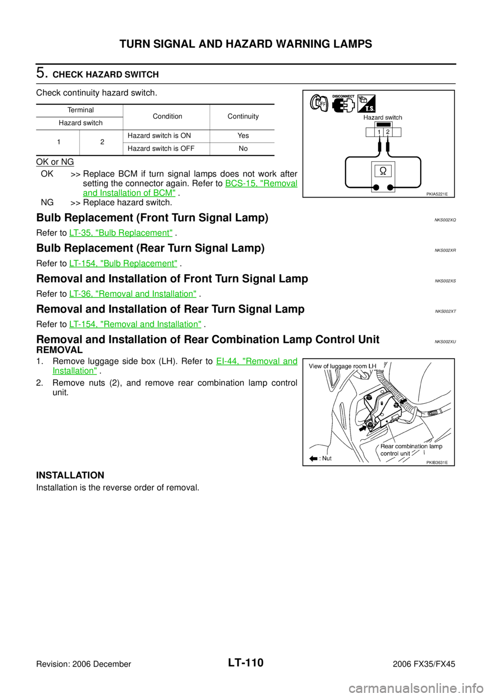
5. CHECK HAZARD SWITCH
Check continuity hazard switch.
OK or NG
OK >> Replace BCM if turn signal lamps does not work after setting the connector again. Refer to BCS-15, "
Removal
and Installation of BCM" .
NG >> Replace hazard switch.
Bulb Replacement (Front Turn Signal Lamp)NKS002XQ
Refer to LT- 3 5 , "Bulb Replacement" .
Bulb Replacement (Rear Turn Signal Lamp)NKS002XR
Refer to LT- 1 5 4 , "Bulb Replacement" .
Removal and Installation of Front Turn Signal LampNKS002XS
Refer to LT- 3 6 , "Removal and Installation" .
Removal and Installation of Rear Turn Signal Lamp NKS002XT
Refer to LT- 1 5 4 , "Removal and Installation" .
Removal and Installation of Rear Combination Lamp Control UnitNKS002XU
REMOVAL
1. Remove luggage side box (LH). Refer to EI-44, "Removal and
Installation" .
2. Remove nuts (2), and remove rear combination lamp control unit.
INSTALLATION
Installation is the reverse order of removal.
Terminal Condition Continuity
Hazard switch
12 Hazard switch is ON Yes
Hazard switch is OFF No
PKIA5221E
PKIB3631E
Page 3692 of 4462
LT-130
STOP LAMP
Revision: 2006 December 2006 FX35/FX45
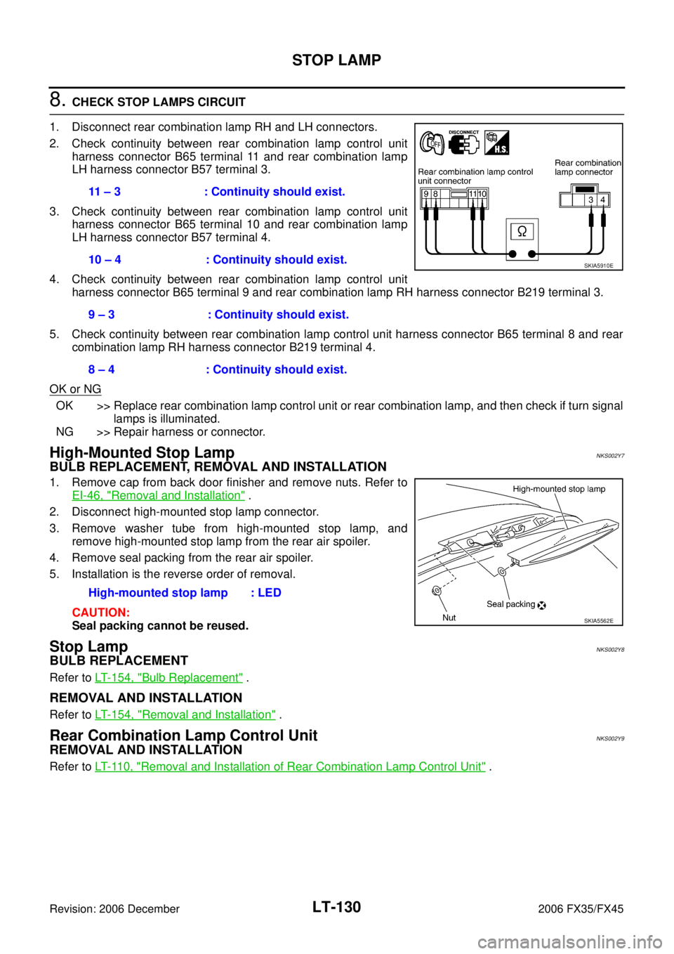
8. CHECK STOP LAMPS CIRCUIT
1. Disconnect rear combination lamp RH and LH connectors.
2. Check continuity between rear combination lamp control unit harness connector B65 terminal 11 and rear combination lamp
LH harness connector B57 terminal 3.
3. Check continuity between rear combination lamp control unit harness connector B65 terminal 10 and rear combination lamp
LH harness connector B57 terminal 4.
4. Check continuity between rear combination lamp control unit harness connector B65 terminal 9 and rear combination lamp RH harness connector B219 terminal 3.
5. Check continuity between rear combination lamp control unit harness connector B65 terminal 8 and rear combination lamp RH harness connector B219 terminal 4.
OK or NG
OK >> Replace rear combination lamp control unit or rear combination lamp, and then check if turn signal lamps is illuminated.
NG >> Repair harness or connector.
High-Mounted Stop LampNKS002Y7
BULB REPLACEMENT, REMOVAL AND INSTALLATION
1. Remove cap from back door finisher and remove nuts. Refer to EI-46, "
Removal and Installation" .
2. Disconnect high-mounted stop lamp connector.
3. Remove washer tube from high-mounted stop lamp, and remove high-mounted stop lamp from the rear air spoiler.
4. Remove seal packing from the rear air spoiler.
5. Installation is the reverse order of removal.
CAUTION:
Seal packing cannot be reused.
Stop LampNKS002Y8
BULB REPLACEMENT
Refer to LT- 1 5 4 , "Bulb Replacement" .
REMOVAL AND INSTALLATION
Refer to LT- 1 5 4 , "Removal and Installation" .
Rear Combination Lamp Control UnitNKS002Y9
REMOVAL AND INSTALLATION
Refer to LT- 11 0 , "Removal and Installation of Rear Combination Lamp Control Unit" .
11 – 3 : Continuity should exist.
10 – 4 : Continuity should exist.
9 – 3 : Continuity should exist.
8 – 4 : Continuity should exist.
SKIA5910E
High-mounted stop lamp : LED
SKIA5562E
Page 3694 of 4462

LT-132
BACK-UP LAMP
Revision: 2006 December 2006 FX35/FX45
Bulb ReplacementNKS003GX
Refer to LT- 1 5 4 , "Bulb Replacement" .
Removal and InstallationNKS003GY
Refer to LT- 1 5 4 , "Removal and Installation" .
Page 3714 of 4462
LT-152
PARKING, LICENSE PLATE AND TAIL LAMPS
Revision: 2006 December 2006 FX35/FX45
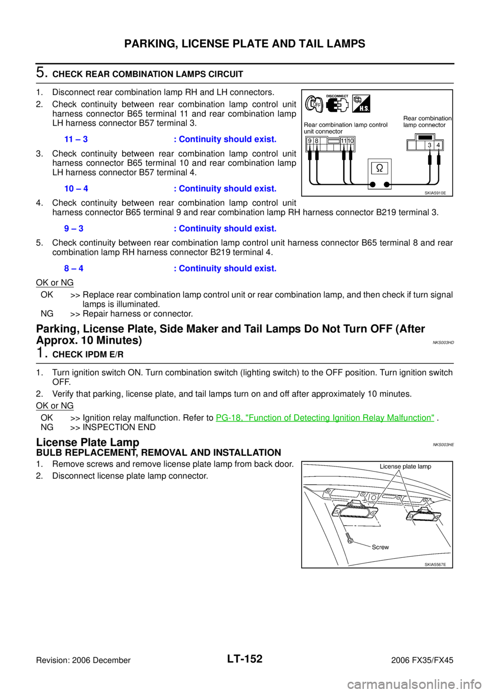
5. CHECK REAR COMBINATION LAMPS CIRCUIT
1. Disconnect rear combination lamp RH and LH connectors.
2. Check continuity between rear combination lamp control unit harness connector B65 terminal 11 and rear combination lamp
LH harness connector B57 terminal 3.
3. Check continuity between rear combination lamp control unit harness connector B65 terminal 10 and rear combination lamp
LH harness connector B57 terminal 4.
4. Check continuity between rear combination lamp control unit harness connector B65 terminal 9 and rear combination lamp RH harness connector B219 terminal 3.
5. Check continuity between rear combination lamp control unit harness connector B65 terminal 8 and rear combination lamp RH harness connector B219 terminal 4.
OK or NG
OK >> Replace rear combination lamp control unit or rear combination lamp, and then check if turn signal lamps is illuminated.
NG >> Repair harness or connector.
Parking, License Plate, Side Maker and Tail Lamps Do Not Turn OFF (After
Approx. 10 Minutes)
NKS003HD
1. CHECK IPDM E/R
1. Turn ignition switch ON. Turn combination switch (lighting switch) to the OFF position. Turn ignition switch OFF.
2. Verify that parking, license plate, and tail lamps turn on and off after approximately 10 minutes.
OK or NG
OK >> Ignition relay malfunction. Refer to PG-18, "Function of Detecting Ignition Relay Malfunction" .
NG >> INSPECTION END
License Plate LampNKS003HE
BULB REPLACEMENT, REMOVAL AND INSTALLATION
1. Remove screws and remove license plate lamp from back door.
2. Disconnect license plate lamp connector. 11 – 3 : Continuity should exist.
10 – 4 : Continuity should exist.
9 – 3 : Continuity should exist.
8 – 4 : Continuity should exist.
SKIA5910E
SKIA5567E
Page 3715 of 4462
PARKING, LICENSE PLATE AND TAIL LAMPS LT-153
C
D E
F
G H
I
J
L
M A
B
LT
Revision: 2006 December 2006 FX35/FX45
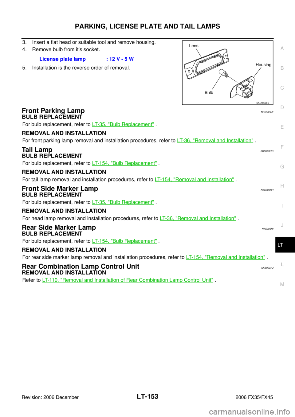
3. Insert a flat head or suitable tool and remove housing.
4. Remove bulb from it's socket.
5. Installation is the reverse order of removal.
Front Parking LampNKS003HF
BULB REPLACEMENT
For bulb replacement, refer to LT- 3 5 , "Bulb Replacement" .
REMOVAL AND INSTALLATION
For front parking lamp removal and installation procedures, refer to LT- 3 6 , "Removal and Installation" .
Ta i l L a m pNKS003HG
BULB REPLACEMENT
For bulb replacement, refer to LT- 1 5 4 , "Bulb Replacement" .
REMOVAL AND INSTALLATION
For tail lamp removal and installation procedures, refer to LT- 1 5 4 , "Removal and Installation" .
Front Side Marker LampNKS003HH
BULB REPLACEMENT
For bulb replacement, refer to LT- 3 5 , "Bulb Replacement" .
REMOVAL AND INSTALLATION
For head lamp removal and installation procedures, refer to LT- 3 6 , "Removal and Installation" .
Rear Side Marker LampNKS003HI
BULB REPLACEMENT
For bulb replacement, refer to LT- 1 5 4 , "Bulb Replacement" .
REMOVAL AND INSTALLATION
For rear side marker lamp removal and installation procedures, refer to LT- 1 5 4 , "Removal and Installation" .
Rear Combination Lamp Control UnitNKS003HJ
REMOVAL AND INSTALLATION
Refer to LT- 11 0 , "Removal and Installation of Rear Combination Lamp Control Unit" .
License plate lamp : 12 V - 5 W
SKIA5568E
Page 3716 of 4462
LT-154
REAR COMBINATION LAMP
Revision: 2006 December 2006 FX35/FX45
REAR COMBINATION LAMPPFP:26554
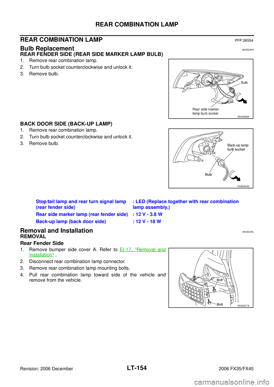
Bulb ReplacementNKS003HK
REAR FENDER SIDE (REAR SIDE MARKER LAMP BULB)
1. Remove rear combination lamp.
2. Turn bulb socket counterclockwise and unlock it.
3. Remove bulb.
BACK DOOR SIDE (BACK-UP LAMP)
1. Remove rear combination lamp.
2. Turn bulb socket counterclockwise and unlock it.
3. Remove bulb.
Removal and InstallationNKS003HL
REMOVAL
Rear Fender Side
1. Remove bumper side cover A. Refer to EI-17, "Removal and
Installation" .
2. Disconnect rear combination lamp connector.
3. Remove rear combination lamp mounting bolts.
4. Pull rear combination lamp toward side of the vehicle and remove from the vehicle.
SKIA5569E
PKIB3634E
Stop/tail lamp and rear turn signal lamp
(rear fender side) : LED (Replace together with rear combination
lamp assembly.)
Rear side marker lamp (rear fender side) : 12 V - 3.8 W
Back-up lamp (back door side) : 12 V - 18 W
SKIA5571E
Page 3747 of 4462
INTERIOR ROOM LAMP LT-185
C
D E
F
G H
I
J
L
M A
B
LT
Revision: 2006 December 2006 FX35/FX45
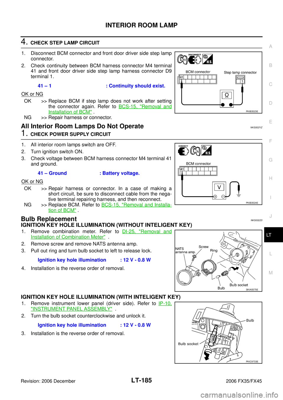
4. CHECK STEP LAMP CIRCUIT
1. Disconnect BCM connector and front door driver side step lamp connector.
2. Check continuity between BCM harness connector M4 terminal 41 and front door driver side step lamp harness connector D9
terminal 1.
OK or NG
OK >> Replace BCM if step lamp does not work after setting the connector again. Refer to BCS-15, "
Removal and
Installation of BCM" .
NG >> Repair harness or connector.
All Interior Room Lamps Do Not OperateNKS002YZ
1. CHECK POWER SUPPLY CIRCUIT
1. All interior room lamps switch are OFF.
2. Turn ignition switch ON.
3. Check voltage between BCM harness connector M4 terminal 41 and ground.
OK or NG
OK >> Repair harness or connector. In a case of making a short circuit, be sure to disconnect cable from the nega-
tive terminal repairing harness, and then reconnect.
NG >> Replace BCM. Refer to BCS-15, "
Removal and Installa-
tion of BCM" .
Bulb ReplacementNKS002Z0
IGNITION KEY HOLE ILLUMINATION (WITHOUT INTELIGENT KEY)
1. Remove combination meter. Refer to DI-25, "Removal and
Installation of Combination Meter" .
2. Remove screw and remove NATS antenna amp.
3. Pull out ring and turn bulb socket to left to release lock.
4. Installation is the reverse order of removal.
IGNITION KEY HOLE ILLUMINATION (WITH INTELIGENT KEY)
1. Remove instrument lower panel (driver side). Refer to IP-10,
"INSTRUMENT PANEL ASSEMBLY" .
2. Turn the bulb socket counterclockwise and unlock it.
3. Installation is the reverse order of removal. 41 – 1 : Continuity should exist.
PKIB3523E
41 – Ground : Battery voltage.
PKIB3524E
Ignition key hole illumination : 12 V - 0.8 W
SKIA5575E
Ignition key hole illumination : 12 V - 0.8 W
PKIC9733E
Page 3765 of 4462
ILLUMINATION LT-203
C
D E
F
G H
I
J
L
M A
B
LT
Revision: 2006 December 2006 FX35/FX45
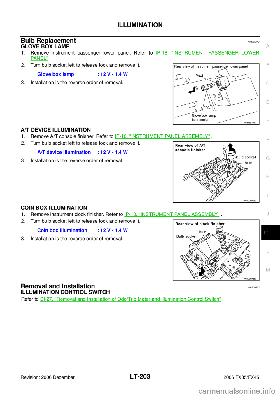
Bulb ReplacementNKS003N7
GLOVE BOX LAMP
1. Remove instrument passenger lower panel. Refer to IP-18, "INSTRUMENT PASSENGER LOWER
PA N E L" .
2. Turn bulb socket left to release lock and remove it.
3. Installation is the reverse order of removal.
A/T DEVICE ILLUMINATION
1. Remove A/T console finisher. Refer to IP-10, "INSTRUMENT PANEL ASSEMBLY" .
2. Turn bulb socket left to release lock and remove it.
3. Installation is the reverse order of removal.
COIN BOX ILLUMINATION
1. Remove instrument clock finisher. Refer to IP-10, "INSTRUMENT PANEL ASSEMBLY" .
2. Turn bulb socket left to release lock and remove it.
3. Installation is the reverse order of removal.
Removal and InstallationNKS002Z7
ILLUMINATION CONTROL SWITCH
Refer to DI-27, "Removal and Installation of Odo/Trip Meter and Illumination Control Switch" .
Glove box lamp : 12 V - 1.4 W
PKIB3636E
A/T device illumination : 12 V - 1.4 W
PKIC9699E
Coin box illumination : 12 V - 1.4 W
PKIC9698E