Page 325 of 4462
ON-VEHICLE SERVICE AT-241
D E
F
G H
I
J
K L
M A
B
AT
Revision: 2006 December 2006 FX35/FX45
11. Disconnect A/T fluid temperature sensor 2 connector. CAUTION:
Be careful not to damage connector.
12. Straighten terminal clips to free terminal cord assembly and A/T fluid temperature sensor 2 harness.
13. Disconnect revolution sensor connector. CAUTION:
Be careful not to damage connector.
14. Straighten terminal clip to free revolution sensor harness.
15. Remove bolts A, B and C from control valve with TCM.
SCIA5023E
SCIA5446E
SCIA7524E
SCIA7525E
Bolt symbol Length mm (in) Number of bolts A 42 (1.65) 5
B 55 (2.17) 6
C 40 (1.57) 1
SCIA5139E
Page 326 of 4462
AT-242
ON-VEHICLE SERVICE
Revision: 2006 December 2006 FX35/FX45
16. Remove control valve with TCM from transmission case. CAUTION:
When removing, be careful with the manual valve notch and
manual plate height. Remove it vertically.
17. Remove A/T fluid temperature sensor 2 with bracket from con- trol valve with TCM.
18. Remove bracket from A/T fluid temperature sensor 2.
19. Remove O-ring from A/T assembly harness connector.
20. Disconnect TCM connectors. CAUTION:
Be careful not to damage connectors.
SCIA5142E
SCIA5301E
SCIA5264E
SCIA5155E
SCIA5447E
Page 328 of 4462
AT-244
ON-VEHICLE SERVICE
Revision: 2006 December 2006 FX35/FX45
3. Connect TCM connectors.
4. Install O-ring in A/T assembly harness connector. CAUTION:
�Do not reuse O-ring.
�Apply ATF to O-ring.
5. Install A/T fluid temperature sensor 2 to bracket.
6. Install A/T fluid temperature sensor 2 (with bracket) in control valve with TCM, and then tighten A/T fluid temperature sensor 2
mounting bolt to the specified torque. Refer to AT- 2 3 9 , "
COM-
PONENTS" .
CAUTION:
Adjust bolt hole of bracket to bolt hole of control valve with
TCM.
7. Install control valve with TCM in transmission case. CAUTION:
�Make sure that turbine revolution sensor securely installs
turbine revolution sensor hole.
�Hang down revolution sensor harness toward outside so
as not to disturb installation of control valve with TCM.
�Adjust A/T assembly harness connector of control valve
with TCM to terminal hole of transmission case.
SCIA5447E
SCIA5155E
SCIA5264E
SCIA5301E
SCIA5034E
Page 329 of 4462
ON-VEHICLE SERVICE AT-245
D E
F
G H
I
J
K L
M A
B
AT
Revision: 2006 December 2006 FX35/FX45
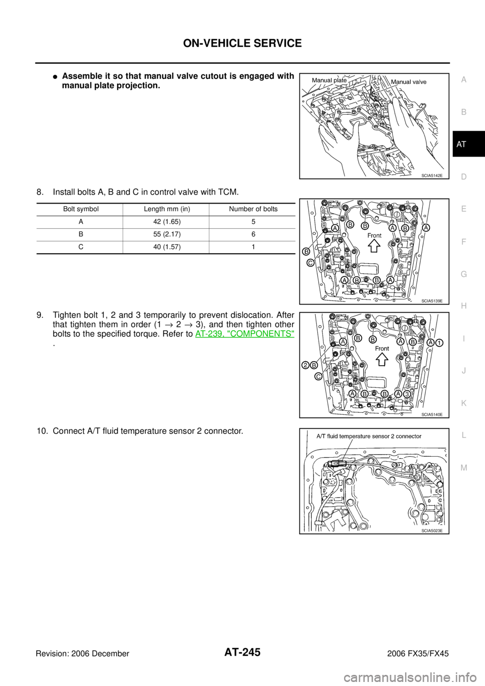
�Assemble it so that manual valve cutout is engaged with
manual plate projection.
8. Install bolts A, B and C in control valve with TCM.
9. Tighten bolt 1, 2 and 3 temporarily to prevent dislocation. After that tighten them in order (1 → 2 → 3), and then tighten other
bolts to the specified torque. Refer to AT- 2 3 9 , "
COMPONENTS"
.
10. Connect A/T fluid temperature sensor 2 connector.
SCIA5142E
Bolt symbol Length mm (in) Number of bolts A 42 (1.65) 5
B 55 (2.17) 6
C 40 (1.57) 1
SCIA5139E
SCIA5140E
SCIA5023E
Page 330 of 4462
AT-246
ON-VEHICLE SERVICE
Revision: 2006 December 2006 FX35/FX45
11. Securely fasten terminal cord assembly and A/T fluid tempera- ture sensor 2 harness with terminal clips.
12. Connect revolution sensor connector.
13. Securely fasten revolution sensor harness with terminal clip.
14. Install magnets in oil pan.
15. Install oil pan to transmission case.
a. Install oil pan gasket to oil pan. CAUTION:
�Do not reuse oil pan gasket.
�Install it in the direction to align hole positions.
�Completely remove all moisture, oil and old gasket, etc. from oil pan gasket mounting surface.
SCIA5446E
SCIA7524E
SCIA7525E
SCIA5200E
Page 331 of 4462
 to transmission case. CAUTION:
�Install it so that drai")
ON-VEHICLE SERVICE AT-247
D E
F
G H
I
J
K L
M A
B
AT
Revision: 2006 December 2006 FX35/FX45
b. Install oil pan (with oil pan gasket) to transmission case. CAUTION:
�Install it so that drain plug comes to the position as
shown in the figure.
�Be careful not to pinch harnesses.
�Completely remove all moisture, oil and old gasket, etc.
from oil pan mounting surface.
c. Tighten oil pan mounting bolts to the specified torque in numeri- cal order shown in the figure after temporarily tightening them.
Refer to AT- 2 3 9 , "
COMPONENTS" .
CAUTION:
Do not reuse oil pan mounting bolts.
16. Install drain plug to oil pan, and then tighten drain plug to the specified torque. Refer to AT- 2 3 9 , "
COMPONENTS" .
CAUTION:
Do not reuse drain plug gasket.
17. Pull up A/T assembly harness connector. CAUTION:
Be careful not to damage connector.
18. Install snap ring to A/T assembly harness connector.
19. Connect A/T assembly harness connector.
20. Connect heated oxygen sensor 2 harness connector.
21. Install front cross bar. Refer to FSU-8, "
Removal and Installa-
tion" .
22. Pour ATF into A/T assembly. Refer to AT- 1 2 , "
Changing A/T
Fluid" .
23. Connect the battery cable to the negative terminal.
A/T FLUID TEMPERATURE SENSOR 2 REMOVAL AND INSTALLATION
Removal
1. Disconnect the battery cable from the negative terminal.
2. Remove front cross bar. Refer to FSU-8, "
Removal and Installation" .
3. Disconnect heated oxygen sensor 2 harness connector.
4. Drain ATF through drain plug.
SCIA2308E
SCIA4113E
SCIA5038E
SCIA5039E
Page 332 of 4462
AT-248
ON-VEHICLE SERVICE
Revision: 2006 December 2006 FX35/FX45
5. Remove oil pan and oil pan gasket.
6. Check foreign materials in oil pan to help determine causes of malfunction. If the ATF is very dark, smells burned, or contains
foreign particles, the frictional material (clutches, band) may
need replacement. A tacky film that will not wipe clean indicates
varnish build up. Varnish can cause valves, servo, and clutches
to stick and can inhibit pump pressure.
�If frictional material is detected, perform A/T fluid cooler
cleaning. Refer to AT- 1 5 , "
A/T Fluid Cooler Cleaning" .
7. Disconnect A/T fluid temperature sensor 2 connector. CAUTION:
Be careful not to damage connector.
8. Straighten terminal clip to free A/T fluid temperature sensor 2 harness.
9. Remove A/T fluid temperature sensor 2 with bracket from con- trol valve with TCM.
SCIA2308E
SCIA5199E
SCIA5023E
SCIA5146E
SCIA5302E
Page 333 of 4462
ON-VEHICLE SERVICE AT-249
D E
F
G H
I
J
K L
M A
B
AT
Revision: 2006 December 2006 FX35/FX45
10. Remove bracket from A/T fluid temperature sensor 2.
Installation
CAUTION:
After completing installation, check A/T fluid leakage and A/F fluid level. Refer to AT- 1 3 , "
Checking A/T
Fluid" .
1. Install A/T fluid temperature sensor 2 to bracket.
2. Install A/T fluid temperature sensor 2 (with bracket) in control valve with TCM, and then tighten A/T fluid temperature sensor 2
mounting bolt to the specified torque. Refer to AT- 2 3 9 , "
COM-
PONENTS" .
3. Connect A/T fluid temperature sensor 2 connector.
SCIA5264E
SCIA5264E
SCIA5302E
SCIA5023E