Page 4285 of 4462
TROUBLE DIAGNOSIS SRS-37
C
D E
F
G
I
J
K L
M A
B
SRS
Revision: 2006 December 2006 FX35/FX45
Trouble Diagnosis: “AIR BAG” Warning Lamp Does Not Turn ONNHS0007K
DIAGNOSTIC PROCEDURE 8
1. CHECK METER FUSE
Check 10A fuse [No. 14, located in fuse block (J/B)].
Refer to PG-3, "
POWER SUPPLY ROUTING CIRCUIT" .
OK or NG
OK >> GO TO 3.
NG >> GO TO 2.
2. CHECK METER FUSE AGAIN
Replace 10A fuse [No. 14, located in fuse block (J/B)] and turn ignition switch ON.
Does the meter fuse blow again?
YES >> Repair or replace the related harness.
NO >> INSPECTION END
3. CHECK HARNESS CONNECTION BETWEEN DIAGNOSIS SENSOR UNIT AND COMBINATION
METER
Disconnect diagnosis sensor unit connector and turn ignition switch ON.
Does “AIR BAG” warning lamp turn on?
YES or NO
YES >> Replace diagnosis sensor unit.
NO >> Replace combination meter assembly.
Page 4286 of 4462
SRS-38
DRIVER AIR BAG MODULE
Revision: 2006 December 2006 FX35/FX45
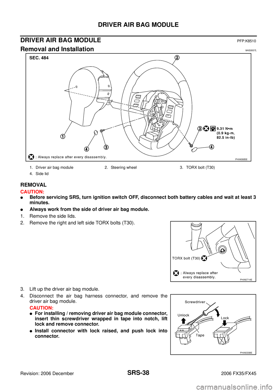
DRIVER AIR BAG MODULEPFP:K8510
Removal and InstallationNHS0007L
REMOVAL
CAUTION:
�Before servicing SRS, turn ignition switch OFF, disconnect both battery cables and wait at least 3
minutes.
�Always work from the side of driver air bag module.
1. Remove the side lids.
2. Remove the right and left side TORX bolts (T30).
3. Lift up the driver air bag module.
4. Disconnect the air bag harness connector, and remove the driver air bag module.
CAUTION:
�For installing / removing driver air bag module connector,
insert thin screwdriver wrapped in tape into notch, lift
lock and remove connector.
�Install connector with lock raised, and push lock into
connector.
PHIA0685E
1. Driver air bag module 2. Steering wheel 3. TORX bolt (T30)
4. Side lid
PHIA0714E
PHIA0308E
Page 4288 of 4462

SRS-40
SPIRAL CABLE
Revision: 2006 December 2006 FX35/FX45
SPIRAL CABLEPFP:25554
Removal and InstallationNHS0007M
REMOVAL
CAUTION:
Before servicing SRS, turn ignition switch OFF, disconnect both battery cables and wait at least 3 min-
utes.
1. Remove driver air bag module. Refer to SRS-38, "
Removal and Installation" .
2. Set the steering wheel in the neutral position.
3. Removal steering wheel. Refer to PS-11, "
Removal and Installation" .
4. Remove steering column covers. Refer to IP-11, "
Removal and Installation" .
5. Loosen the spiral cable fixing screws, and then remove the spiral cable.
CAUTION:
�Do not disassemble spiral cable.
�Do not apply lubricant to the spiral cable.
6. Disconnect the horn switch connector, and then the spiral cable connector.
CAUTION:
�Do not tap or bump the steering wheel.
�Also, with the steering linkage disconnected the cable
may snap by turning the steering wheel beyond the lim-
ited number of turns.
7. Remove the wiper washer switch and lighting switch from the spiral cable.
INSTALLATION
Install in the reverse order of removal.
PHIA1336E
1. Steering wheel 2. Spiral cable 3. Driver air bag module connector
4. Screw 5. Wiper and washer switch 6. Lighting and turn signal switch
7. Steering column assembly 8. Steering column cover (upper) 9. Steering column cover (lower)
SHIA0193E
Page 4290 of 4462

SRS-42
FRONT PASSENGER AIR BAG MODULE
Revision: 2006 December 2006 FX35/FX45
FRONT PASSENGER AIR BAG MODULEPFP:K8515
Removal and InstallationNHS0007N
REMOVAL
CAUTION:
�Before servicing SRS, turn ignition switch OFF, disconnect both battery cables and wait at least 3
minutes.
�Always work from the side of or under front passenger air bag module.
1. Disconnect front passenger air bag module connector (1).
2. Remove glove box assembly and instrument passenger lower panel. Refer to IP-11, "
Removal and Instal-
lation" .
3. Remove display control unit, if navigation system is equipped.
4. Remove tire pressure warning control unit, if tire pressure warning control system is equipped.
5. Remove the front passenger air bag module fixing bolt and nuts, then remove front passenger air bag module.
CAUTION:
�Always place front passenger air bag module with caution
label side facing upward.
�Do not insert any foreign objects (screwdriver, etc.) into
front passenger air bag module.
�Do not disassemble front passenger air bag module.
�Do not use old bolts after removal; replace with new bolts.
PHIA1337E
PHIA0322E
PHIA0325E
Page 4292 of 4462

SRS-44
SIDE CURTAIN AIR BAG MODULE
Revision: 2006 December 2006 FX35/FX45
SIDE CURTAIN AIR BAG MODULEPFP:985P0
Removal and InstallationNHS0007O
REMOVAL
CAUTION:
�Before servicing SRS, turn ignition switch OFF, disconnect both battery cables and wait at least 3
minutes.
�Always work from the side of the side curtain air bag module.
1. Remove headlining. Refer to EI-42, "
Removal and Installation" .
2. Disconnect side curtain air bag connector.
3. Remove side curtain air bag module fixing bolts, and remove the side curtain air bag module.
CAUTION:
�Always place the side curtain air bag module with the warn-
ing label facing upward.
�Do not disassemble side curtain air bag module.
�Do not insert any foreign objects (screwdriver, etc.) into air
bag module connector.
�Replace side curtain air bag module if it has been dropped
or sustained an impact.
�Do not expose the air bag module to temperatures exceed-
ing 90 °C (194 °F).
�Do not allow oil, grease or water to come in contact with the
side curtain air bag module.
1. Side curtain air bag Inflator 2. Side curtain air bag 3. Bolt
4. Assist grip bracket 5. Bolt (There is no torque control)
PHIA0656E
PHIA0317E
SBF814E
Page 4294 of 4462
SRS-46
CRASH ZONE SENSOR
Revision: 2006 December 2006 FX35/FX45
CRASH ZONE SENSORPFP:98531
Removal and InstallationNHS0007P
REMOVAL
CAUTION:
Before servicing SRS, turn ignition switch OFF, disconnect both battery cables and wait at least 3 min-
utes.
1. Remove front grille. Refer to EI-22, "
Removal and Installation" .
2. Remove crash zone sensor connector.
3. Remove crash zone sensor fixing nuts.
CAUTION:
�Replace crash zone sensor if it has been dropped or sustained an impact.
�Do not disassemble crash zone sensor.
INSTALLATION
Install in the reverse order of removal.
CAUTION:
�Check crash zone sensor for proper installation.
�After the work is complete, perform self-diagnosis to make sure that no malfunction is detected.
Refer to SRS-19, "
SRS Operation Check" .
PHIA0316E
Page 4295 of 4462
 SENSOR SRS-47
C
D E
F
G
I
J
K L
M A
B
SRS
Revision: 2006 December 2006 FX35/FX45
SIDE AIR BAG (SATELLITE) SENSORPFP:98830
Removal and InstallationNHS0007Q
REMOVAL")
SIDE AIR BAG (SATELLITE) SENSOR SRS-47
C
D E
F
G
I
J
K L
M A
B
SRS
Revision: 2006 December 2006 FX35/FX45
SIDE AIR BAG (SATELLITE) SENSORPFP:98830
Removal and InstallationNHS0007Q
REMOVAL
CAUTION:
Before servicing SRS, turn ignition switch OFF, disconnect both battery cables and wait at least 3 min-
utes.
1. Remove seat belt pre-tensioner. Refer to SB-4, "
Removal and Installation of Front Seat Belt" .
2. Remove side air bag (Satellite) sensor fixing nuts.
3. Remove the side air bag (Satellite) sensor connector.
CAUTION:
�Do not use old nuts; replace with new ones.
�Check side air bag (Satellite) sensor to ensure it is free of deformities, dents, cracks or rust. If it
shows any visible signs of damage, replace it with new one.
�Do not disassemble side air bag (Satellite) sensor.
�Replace side air bag (Satellite) sensor if it has been dropped or sustained an impact.
INSTALLATION
Install in the reverse order of removal.
CAUTION:
�Check side air bag (Satellite) sensor for proper installation.
�After replacement of side air bag (Satellite) sensor, perform self-diagnosis to make sure that no
malfunction is detected. Refer to SRS-19, "
SRS Operation Check" .
PHIA0314E
Page 4297 of 4462

DIAGNOSIS SENSOR UNIT SRS-49
C
D E
F
G
I
J
K L
M A
B
SRS
Revision: 2006 December 2006 FX35/FX45
DIAGNOSIS SENSOR UNITPFP:28556
Removal and InstallationNHS0007S
REMOVAL
CAUTION:
Before servicing SRS, turn ignition switch OFF, disconnect both battery cables and wait at least 3 min-
utes.
1. Disconnect each harness connector for the air bag module and seat belt pre-tensioner.
2. Remove center console. Refer to IP-11, "
Removal and Installation" .
3. Disconnect diagnosis sensor unit connector.
4. Remove special bolts (T50) from the diagnosis sensor unit.
CAUTION:
�Do not use old bolts. Replace with new ones.
�Check diagnosis sensor unit bracket to ensure it is free of
deformities, dents, cracks or rust. If it shows any visible
things of damage, replace with new one.
�Replace diagnosis sensor unit if it has been dropped or
sustained an impact.
INSTALLATION
Install in the reverse order of removal.
CAUTION:
�Check the diagnosis sensor unit for proper installation.
�After replacement of diagnosis sensor unit, perform self-diagnosis to make sure that no malfunc-
tion is detected. Refer to SRS-19, "
SRS Operation Check" .
ECU DISCRIMINATED NO.
After replacing the diagnosis sensor unit, confirm that the diagnosis sensor unit identification is correct for the
vehicle as equipped.
PHIA0315E
Specification ECU DISCRIMINATED No.
Models with driver and passenger air bags, seat belt pre-tensioner, side air bags and curtain air bags FB04